CF188发动机使用说明书
汽油发电机原理图
目录一、安全使用须知 1 四、使用说明16二、发电机组使用维护图例说明 2 1、机组起动前的检查161、各部位名称 22、机组起动、运行162、使用前检查 43、停机163、起动发电机组 54、发电机组使用注意事项174、发电机组使用方法8 五、维护保养175、停机步骤11 1、日常维护176、维护保养12 2、定期维护187、贮存14 3、正常维护程序18三、机组主要技术参数14 4、长期停放的维护191、机组外形尺寸与重量15 六、故障分析与排除202、发动机、发电机15 七、电器原理图24一、安全使用需知机组使用前请仔细阅读使用说明书。
机组工作场地应选择平坦、通风良好、无易燃、易爆物和远离火源的地方,禁止在密闭的室内使用;使用过程中应防止小孩及动物接近机组和电源线。
建议机组不连接到家庭照明线路上,如需连接作为备用电源需与市电网时,应由经过专业培训的人员安装线路,必须备有独立的短路装置,防止市电供电烧毁机组。
机组操作人员在使用机组前,应检查机组各部连接是否处于正确的位置,各开关是否处于待机工作状态,各紧固件是否有松脱。
机组在运行状态中严禁搬动,应经常注意机组运行是否正常。
加机油时必须停止机组运行,并且禁止吸烟。
机组严禁超负荷运行。
在使用过程中,请勿触摸高温部位(如:缸头、消声器等),以防灼伤。
沼气成分中含有杂质、硫、水份等对发动机运行有影响,在使用沼气发电前最好对沼气进行过滤、脱硫、脱水处理。
1二、发电机组使用维护图例说明线路保护机油尺放油螺栓机油传感器混合器2空气滤清器32、使用前检查机油油位检查 3) 取出机油尺,看油位是否在油位上限和下限之间, 注意:牢记本操作应在平坦地面上停止机组运行后进行 如油位低于下限,则请将机油加至于机油尺上限,见图 1) 取出机油尺,用干净抹布清洁机油尺,见图。
2) 将机油尺插进油口,此时请勿旋转油尺。
4)拧紧机油尺,见图。
3、起动发电机组1、将气管接头与发电机的进气接口相连接, 3、将线路保护器(交流以输出开关)关闭。
湛金斯4式3.979英寸4筒燃油发动机商品说明书
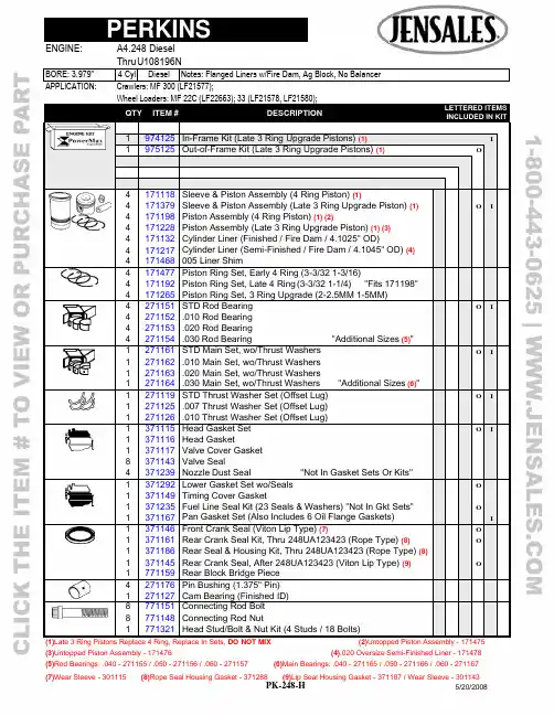
APPLICATION: Crawlers: MF 300 (LF21577);Wheel Loaders: MF 22C (LF22663); 33 (LF21578, LF21580);QTY ITEM # DESCRIPTION LETTERED ITEMSINCLUDED IN KIT1 974125 In-Frame Kit (Late 3 Ring Upgrade Pistons) (1) I1 975125 Out-of-Frame Kit (Late 3 Ring Upgrade Pistons) (1) O4 171118 Sleeve & Piston Assembly (4 Ring Piston) (1)4 171379 Sleeve & Piston Assembly (Late 3 Ring Upgrade Piston) (1) O I4 171198 Piston Assembly (4 Ring Piston) (1) (2)4 171228 Piston Assembly (Late 3 Ring Upgrade Piston) (1) (3)4 171132 Cylinder Liner (Finished / Fire Dam / 4.1025" OD)4 171217 Cylinder Liner (Semi-Finished / Fire Dam / 4.1045" OD) (4)4 171468 005 Liner Shim4 171477 Piston Ring Set, Early 4 Ring (3-3/32 1-3/16)4 171192 Piston Ring Set, Late 4 Ring (3-3/32 1-1/4) "Fits 171198"4 171265 Piston Ring Set, 3 Ring Upgrade (2-2.5MM 1-5MM)4 271151 STD Rod Bearing O I4 271152 .010 Rod Bearing4 271153 .020 Rod Bearing4 271154 .030 Rod Bearing "Additional Sizes (5)"1 271161 STD Main Set, wo/Thrust Washers O I1 271162 .010 Main Set, wo/Thrust Washers1 271163 .020 Main Set, wo/Thrust Washers1 271164 .030 Main Set, wo/Thrust Washers "Additional Sizes (6)"1 271119 STD Thrust Washer Set (Offset Lug) O I1 271125 .007 Thrust Washer Set (Offset Lug)1 271126 .010 Thrust Washer Set (Offset Lug)1 371115 Head Gasket Set O I1 371116 Head Gasket1 371117 Valve Cover Gasket8 371143 Valve Seal4 371239 Nozzle Dust Seal "Not In Gasket Sets Or Kits"1 1 1 1 371292 371149 371235 371167 Lower Gasket Set wo/Seals Timing Cover Gasket Fuel Line Seal Kit (23 Seals & Washers) "Not In Gkt Sets" Pan Gasket Set (Also Includes 6 Oil Flange Gaskets) O OI1 371146 Front Crank Seal (Viton Lip Type) (7) O1 371161 Rear Crank Seal Kit, Thru 248UA123423 (Rope Type) (8) O1 371186 Rear Seal & Housing Kit, Thru 248UA123423 (Rope Type) (8)1 371145 Rear Crank Seal, After 248UA123423 (Viton Lip Type) (9) O1 771159 Rear Block Bridge Piece4 271176 Pin Bushing (1.375" Pin)1 271127 Cam Bearing (Finished ID)8 771151 Connecting Rod Bolt 8 771148 Connecting Rod Nut1 771321 Head Stud/Bolt & Nut Kit (4 Studs / 18 Bolts)(1)Late 3 Ring Pistons Replace 4 Ring, Replace In Sets, DO NOT MIX (2)Untopped Piston Assembly - 171475(3)Untopped Piston Assembly - 171476 (4).020 Oversize Semi-Finished Liner - 171478(5)Rod Bearings: .040 - 271155 / .050 - 271156 / .060 - 271157 (6)Main Bearings: .040 - 271165 / .050 - 271166 / .060 - 271167APPLICATION: Crawlers: MF 300 (LF21577);Wheel Loaders: MF 22C (LF22663); 33 (LF21578, LF21580);QTY ITEM # DESCRIPTION LETTERED ITEMSINCLUDED IN KIT1 979516 Camshaft Kit C1 979143 Valve Train Kit V1 979139 Valve Train Kit, w/Guides V1 571122 Camshaft "Cam Bolt Lock Plate - 571162" C1 271249 Camshaft Thrust Washer (1.750 X 2.873 X .217)8 571123 Tappet C4 4 471123 471128 STD Exhaust Valve (45º / Bi-Metal) (10) STD Intake Valve (45º / Alloy / Chromed Stem) (11) V V V V4 471132 Exhaust Guide: Service Repair or 1985 & Up V4 471131 Intake Guide: Service Repair or 1985 & Up V8 471134 Outer Valve Spring (8 Coils / 2.500" Free Length) V V8 471133 Inner Valve Spring (9 Coils / 2.000" Free Length) V V8 471219 Spring Seat, Integral Guides "With Service Guides - 471229"8 471222 Spring Retainer16 471146 Keeper (Half) V V4 471111 Exhaust Seat (1.248 x 1.681 x .374 Stepped Top)4 471113 Intake Seat (1.594 x 2.020 x .281)4 471224 LH Rocker Arm (Adj Screw & Lock Nut Not Included) (12)4 471225 RH Rocker Arm (Adj Screw & Lock Nut Not Included) (12)1 471227 Rocker Arm Shaft (13) "Includes 471176 Plugs"1 571165 Cam Gear (Steel / 56 Teeth)1 571113 Crank Gear (28 Teeth) 1 571163 Idler Gear (Steel / 63T)2 571144 Idler Gear Bushing1 571145 Idler Gear Hub8 571117 Push Rod1 671112 Oil Pump1 671134 Oil Pump Idler Gear1 571124 Idler Gear Bushing1 671148 Relief Valve Assembly (Engines w/LH Oil Filter Only)1 771129 Crank Kit, Thru 248UA123423 (Spline Nose / Rope Seal)1 771132 Crank Kit, After 248UA123423 (Spline Nose / Lip Seal)4 771154 Connecting Rod (1.375" Pin)1 771264 Cylinder Head Assembly (Includes Valves & Springs)1 771286 Expansion Plug Kit (Includes 19 Plugs For Head & Block)1 871138 Thermostat (2.125" / Bypass)1 871229 Water Pump wo/Pulley: Except LF226631 871228 Block Heater (1.250")1 871225 Fuel Pump, Early (2 Bolt/Horizontal Diaphram)1 871152 Fuel Pump, Late (4 Bolt)(10)Oversizes: .003 - 471271 / .015 - 471272 / .030 - 471273 (11)Oversizes: .003 - 471274 / .015 - 471275 / .030 - 471276。
cf188发动机说明书
cf188发动机说明书CF188发动机说明书第一章介绍本章主要介绍CF188发动机的概述、用途、技术指标和主要特点。
1.1 概述CF188发动机是一款先进的航空发动机,采用了最新的技术和工艺,具有出色的性能和可靠性。
1.2 用途CF188发动机适用于各种型号的军用飞机,包括喷气式和涡轮螺旋桨飞机等。
1.3 技术指标CF188发动机的主要技术指标包括最大推力、燃油消耗率、推力重量比等。
1.4 主要特点CF188发动机具有以下主要特点:- 高效率: 采用先进的燃烧室和涡轮,提高了燃烧效率和推力重量比。
- 低噪音: 通过优化设计和先进的降噪技术,减少了发动机运行时的噪音。
- 可靠性: 采用了先进的故障检测和排除系统,提高了发动机的可靠性和维修性。
第二章结构与工作原理本章主要介绍CF188发动机的结构组成和工作原理。
2.1 发动机结构CF188发动机由压气机、燃烧室、涡轮和喷管等组件组成。
2.2 工作原理CF188发动机的工作原理是通过压气机将空气压缩,然后与燃料混合燃烧,产生高温高压气体驱动涡轮转动,最后由喷管排出高速气流。
第三章维护和维修本章主要介绍CF188发动机的维护和维修方法,包括例行检查、故障排除和零部件更换等。
3.1 例行检查CF188发动机的例行检查包括外观检查、润滑系统检查、燃油系统检查和故障记录等。
3.2 故障排除CF188发动机的故障排除方法包括故障检测、故障诊断和故障排除等。
3.3 零部件更换CF188发动机的常见零部件更换包括涡轮叶片、燃烧室和喷管等。
第四章安全与环保本章主要介绍CF188发动机的安全性能和环保措施。
4.1 安全性能CF188发动机具有可靠的安全性能,采用了多重安全保护措施,包括高温报警、故障自动切断和紧急停机等。
4.2 环保措施CF188发动机符合国际环保标准,采用了先进的减排技术,减少了有害气体和颗粒物的排放。
附件:1: CF188发动机技术参数表2: CF188发动机维护手册3: CF188发动机故障排除流程图法律名词及注释:1:技术指标:指描述产品、设备等技术性能的参数和要求。
THPCS16汽油链锯操作手册和零件清单说明书

• Beware of small branches and saplings whipping back towards you as you cut. When cutting a limb which is under tension, be alert to the possibility of the limb springing back when the tension is released.
• Use a ratio of 25:1 unleaded petrol to 2-stroke mineral oil. For semi-synthetic or synthetic use the manufacturer’s ratio. Mix in an appropriate mixing bot-
Ruler Gap
No gap Chain tilts
PARTS DIAGRAM AND LIST
(
I
I/ I" /
1/i 112
No Part No Description
Qty No Part No Description
Qty
1
TH159-1 Nut Muffler
2
2
TH159-2 Muffler Assy
• Ensure that bystanders, children and pets keep well away when starting or cutting - at least 10m.
常发柴油机使用说明书

一、燃油、机油和冷却水 .................................................................................................................................. 47 二、起动前的准备..............................................................................................................................................47 三、柴油机的起动..............................................................................................................................................47 四、柴油机的运转..............................................................................................................................................48 五、柴油机的停车..............................................................................................................................................48
林肯(Lincoln)电缸加热器操作手册说明书
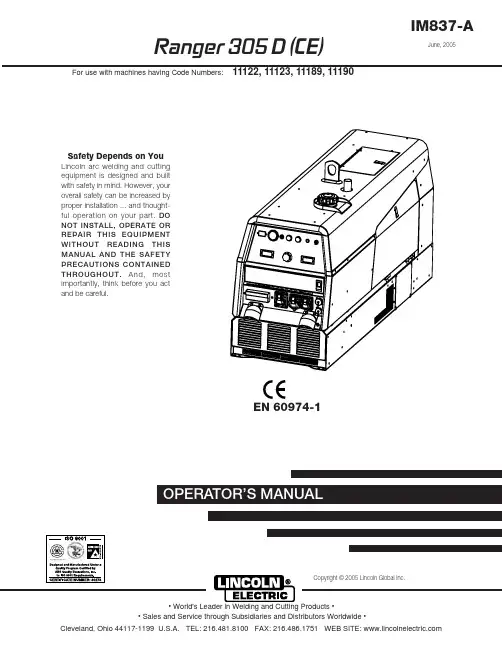
Ranger 305 D (CE)OPERATOR’S MANUALIM837-AJune, 2005Safety Depends on YouLincoln ar c welding and cutting equipment is designed and built with safety in mind. However, your overall safety can be increased by proper installation ... and thought-ful oper ation on your par t.DO NOT INSTALL, OPERATE OR REPAIR THIS EQUIPMENT WITHOUT READING THIS MANUAL AND THE SAFETY PRECAUTIONS CONTAINED THROUGHOUT.And, most impor tantly, think befor e you act and be careful.EN 60974-1Copyright © 2005 Lincoln Global Inc.Mar ‘95Mar ‘95Mar. ‘93c/o Balmes, 89 - 80 2a 08008 Barcelona SPAINMeasured sound power level:LWA 98 dB (net power Pel = 7.5kW) LWA 96 dB (net power Pel = 7.5k W)26 April 2005Dario Gatti,ixixfor selecting a QUALITY product by Lincoln Electric. We want you to take pride in operating this Lincoln Electric Company product ••• as much pride as we have in bringing this product to you!Page Installation.......................................................................................................................Section A Technical Specifications.......................................................................................................A-1 Safety Precautions........................................................................................................A-2Location and Ventilation................................................................................................A-2Stacking........................................................................................................................A-2Angle of Operation........................................................................................................A-2Lifting.............................................................................................................................A-2High Altitude Operation.................................................................................................A-2High Temperature Operation........................................................................................A-2Cold Weather Operation...............................................................................................A-2Towing...........................................................................................................................A-3Vehicle Mounting...........................................................................................................A-3 Pre-Operation Engine Service..............................................................................................A-3 Oil..................................................................................................................................A-3Fuel...............................................................................................................................A-3Engine Coolant..............................................................................................................A-4Battery Connections......................................................................................................A-4Muffler Outlet Pipe........................................................................................................A-4Spark Arrester...............................................................................................................A-4Remote Control.............................................................................................................A-4 Electrical Connections..........................................................................................................A-4 Machine Grounding.......................................................................................................A-4Welding Terminals........................................................................................................A-5Welding Output Cables.................................................................................................A-5Cable Installation...........................................................................................................A-5 Auxiliary Power ....................................................................................................................A-5 Standby Power Connections................................................................................................A-5 Connection of Lincoln Electric Wire Feeders................................................................A-6,A-7 ________________________________________________________________________________ Operation.........................................................................................................................Section B Safety Precautions ..............................................................................................................B-1 General Description..............................................................................................................B-1 For Auxiliary Power..............................................................................................................B-1 Engine Operation..................................................................................................................B-1 Break in Period.....................................................................................................................B-1 Add Fuel...............................................................................................................................B-1 Fuel ......................................................................................................................................B-1 Welder Controls............................................................................................................B-2Engine Controls.............................................................................................................B-3Starting and Stopping the Engine...........................................................................B-3, B4Stopping .......................................................................................................................B-4 Welding Operation................................................................................................................B-5 Duty Cycle.....................................................................................................................B-5Constant Current (Stick) Welding..................................................................................B-5Downhill Pipe (Stick) Welding.......................................................................................B-5Tig Welding...................................................................................................................B-5Typical Current Ranges for Tungsten Electrodes.........................................................B-5Wire Welding-CV...........................................................................................................B-6Arc Gouging..................................................................................................................B-6Auxiliary Power.............................................................................................................B-6 ________________________________________________________________________________ Accessories.....................................................................................................Section C Field Installed Options / Accessories ...............................................................................C-1 ________________________________________________________________________________Check with distributor for the recommended trailer for use with this equipment for road, in-plant and yard towing by a vehicle. If the user adapts a non-Lincoln trailer, he must assume responsi-bility that the method of attachment and usage does not result in a safety hazard nor damage the welding equipment. Some of the factors to be considered are as follows:1. Design capacity of trailer vs. weight of Lincoln equipment and likely additional attachments.2.Proper support of, and attachment to, the base of the weld-ing equipment so there will be no undue stress to the frame-work.3.Proper placement of the equipment on the trailer to insurestability side to side and front to back when being moved and when standing by itself while being operated or ser-viced.4. Typical conditions of use, i.e., travel speed; roughness of sur-face on which the trailer will be operated; environmental con-ditions; like maintenance.5. Conformance with laws in nation / region to be used.• The installation complies with the National Electrical Code and all other applicable electri-cal codes.•The premises is isolated and no feedback into the utility system can occur. Certain laws require the premises to be isolated before the generator is linked to the premises. Check your local requirements.-----------------------------------------------------------------------CONNECTION OF LINCOLN ELECTRIC WIRE FEEDERSConnection of LN-15 to the Ranger 305DThese connections instructions apply to both the LN-15 Across The-Arc and Control Cable models. The LN-15 has an internal contactor and the electrode is not energized until the gun trigger is closed. When the gun trigger is closed the wire will begin to feed and the welding process is started.• Shut the welder off.• For electrode Positive, connect the electrode cable to the "+" terminal of the welder and work cable to the "-" terminal of the welder. For electrode Negative, connect the electrode cable "-" terminal of the welder and work cable to the "+" terminal of the welder.• Across The-Arc Model:Attach the single lead from the front of the LN-15 to work using the spring clip at the end of the lead. This is a control lead to supply current to the wire feeder motor; it does not carry welding current.Set the "WELD TERMINALS" switch to "WELD TER-MINALS ON".• Control Cable Model:Connect Control Cable between Engine Welder and Feeder.Set the MODE switch to the "CV-WIRE " position. Set the "WELD TERMINALS" switch to "REMOTELY CONTROLLED".Set the "WIRE FEEDER VOLTMETER" switch to either "+" or "-" as required by the electrode polarity being used.Set the "ARC CONTROL" knob to "0" initially and adjust to suit.Set the "IDLE" switch to the "AUTO" position. 0AUXILIARY POWER:Start the engine and set the IDLER control switch tothe desired operating mode. Full power is availableregardless of the welding control settings providing no welding current is being drawn.Simultaneous Welding and Auxiliary Power Loads While welding, the amount of 3-phase Auxiliary power available is reduced.(See table A.4)When in the TOUCH START TIG mode and when a Amptrol is connected to the 6-pin Connector the OUT-PUT dial is used to set the maximum current range of the CURRENT CONTROL of the Amptrol.The ARC CONTROL is not active in the TIG mode.The RANGER 305D (CE) can be used in a wide variety of DC TIG welding applications. In general the ‘Touch Start’ feature allows contamination free starting without the use of a Hi-frequency unit. If desired, the K930-2TIG Module can be used with the RANGER 305D (CE).The settings are for reference.RANGER 305D (CE) settings when using the K930-2TIG Module with an Amptrol or Arc Start Switch:• Set the MODE Switch to the TOUCH START TIG setting.• Set the "IDLER" Switch to the "AUTO" position.• Set the "WELDING TERMINALS" switch to the"REMOTELY CONTROLLED" position. This will keepthe "Solid State" contactor open and provide a “cold”electrode until the Amptrol or Arc Start Switch ispressedWhen using the TIG Module,the OUTPUT control on the RANGER 305D (CE) is used to set the maximumrange of the CURRENT CONTROL on the TIG module or an Amptrol if connected to the TIG Module. (See Table B.2.)WIRE WELDING-CV Connect a wire feeder to the Ranger 305D according to the instructions in INSTALLATION INSTRUCTIONS Section.The RANGER 305D (CE) in the CV-WIRE mode, per-mits it to be used with a broad range of flux cored wire (Innershield and Outershield) electrodes and solid wires for MIG welding (gas metal arc welding). Welding can be finely tuned using the ARC CONTROL. Turning the ARC CONTROL clockwise from –10 (soft) to +10 (crisp)changes the arc from soft and washed-in to crisp and narrow. It acts as an inductance/pinch control. The proper setting depends on the procedure and operator preference. Start with the dial set at 0.TABLE A.4FIELD INSTALLED OPTIONS / ACCESSORIESK1898-1 SPARK ARRESTOR- Mounts between muf-fler & elbow to eliminate any risk of spark from exhaust. K704 ACCESSORY SET- Includes (10m) 35 ft. of electrode cable and (9.m) 30 ft. of work cable, head-shield, work clamp electrode holder. Cables are rated at 400 amps, 100% duty cycle.K857(7.6m) 25 ft. or K857-1(30.4m) 100 ft. REMOTE CONTROL - Portable control provides same dial range as the output control on the welder. Has a convenient 6 pin plug for easy connection to the welder.ENGINE OIL CHANGEDrain the engine oil while the engine is warm to assure rapid and complete draining. It is recommend-ed that each time the oil is changed the oil filter be changed as well.• Be sure the unit is off. Disconnect the negative bat-tery cable to ensure safety.• Locate oil drain hose and valve in bottom of base and pull through the hole in the battery access panel on the welder.• Remove the cap from the drain valve. Push valve in and twist counterclockwise. Pull to open and drain the oil into a suitable container for disposal.• Close the drain valve by pushing in and twisting clockwise. Replace the cap.• Re-fill the crankcase to the upper limit mark on the dipstick with the recommended oil (see engine oper-ation manual OR engine service items decal OR below). Replace and tighten the oil filler cap secure-ly.• Push oil drain hose and valve back into unit, re-con-nect negative battery cable, and close doors and engine top cover before restarting unit.Wash your hands with soap and water after handling used motor oil. Please dispose of used motor oil in a manner that is compatible with the environment. We suggest you take it in a sealed container to your local service station or recycling center for reclama-tion. DO NOT throw it in the trash; pour it on the ground or down a drain.ENGINE OIL REFILL CAPACITIESWithout oil filter replacement:• 3.2 liter (3.3 U.S. Quart)With oil filter replacement:• 3.2 liter ( 3.4 U.S. Quart.)Use motor oil designed for diesel engines that meets requirements for API service classification CC/CD/CE/CF/CF-4/CG-4 or CH-4.ACEA E1/E2/E3. Always check the API service label on the oil container to be sure it includes the letters indicated. (Note: An S-grade oil must not be used in a diesel engine or damage may result. It IS permissible to use an oil that meets S and C grade service classifi-cations.)SAE 10W30 is recommended for general, all tempera-ture use, -15C to 40C (5F to 104F).See engine owner’s manual for more specific informa-tion on oil viscosity recommendations.removal/installation. Most latchesare spring loaded to fold back when open. The filter fits tightly over the outlet tube, creating the critical seal on the inside diameter of the filter endcap. The filter should be removed gently to reduce the amount of dust dislodged. There will be some initial resistance, similar to breakingClean Sealing Surface 3of the Outlet Tube Use a clean cloth to wipe the sealing surface. Dust on the outside diameter of theoutlet tube could hindernew filter is inserted.Insert the New7RadialSealô Filter by HandInsert carefully. Seat the new filter by hand, making certain it is completely into the air cleaner housing before latching the cover in place. If the cover hits the filter before it is fully in place, remove the cover and push (by hand) thefilter further intothe air cleanerwith no extra force.Never use the latches on the cover to force the filter into the air cleaner! It is tempting to assume the cover will do the job of seating the filter ñ but it will not! Using the latches to push the filter in could cause damage to the housing and will void theClean the Inside of 4the Outlet Tube Carefully wipe the insideof the outlet tubewith a clean cloth.Dirt accidentlytransferred to theinside of the outlettube will reach theengine and cause wear.(Engine manufacturers says that it takes only a few grams of dirt to ëdustí an engine!) Be careful not to damage the sealing area on the tube.of leaks. A streak of dust onthe clean side of the filterInspect the NewFilter for DamageInspect the new filter carefully,paying attention to the inside ofthe open end,which is thesealing area.NEVER installa damaged filter.This Troubleshooting Guide is provided to help you locate and repair possible machine malfunctions.Simply follow the three-step procedure listed below.Step 1.LOCATE PROBLEM (SYMPTOM).Look under the column labeled “PROBLEM (SYMP-TOMS)”. This column describes possible symptoms that the machine may exhibit. Find the listing that best describes the symptom that the machine isexhibiting.Step 2.POSSIBLE CAUSE.The second column labeled “POSSIBLE CAUSE ” lists the obvious external possibilities that may contribute to the machine symptom.Step 3.RECOMMENDED COURSE OF ACTIONThis column provides a course of action for the Possible Cause, generally it states to contact your local Lincoln Authorized Field Service Facility.If you do not understand or are unable to perform the Recommended Course of Action safely, contact your local Lincoln Authorized Field Service Facility.HOW TO USE TROUBLESHOOTING GUIDEService and Repair should only be performed by Lincoln Electric Factory Trained Personnel.Unauthorized repairs performed on this equipment may result in danger to the technician and machine operator and will invalidate your factory warranty. For your safety and to avoid Electrical Shock, please observe all safety notes and precautions detailed throughout this manual.__________________________________________________________________________。
EQD国Ⅲ柴油发动机使用说明书
第一章主要技术规格1.1 基本结构参数-1 --2 -1.2主要性能参数1.3 主要结构特征1.3.1 气缸体铸铁HT250,有龙门,右侧铸有装机冷器的腔,镶干式硼铸铁缸套,下止口定位。
-3 -1.3.2 气缸盖铸铁HT2O0整体式,镶进、排气阀座圈和气阀导管。
1.3.3 活塞共晶硅铝合金,顶部铸“①”型燃烧室有挤流小平台,活塞裙部形线为中凸变椭圆,头部表面为锥—椭圆。
头部有三道环槽(两道气环、一道油环槽),第一环槽镶嵌奥氏体铸铁耐磨圈,楔形销座销孔内侧有微量“喇叭口”。
1.3.4 活塞环一环为球墨铸铁环,型式为T形环105X 3DIN70914;二环为灰铸铁(标准材料)外圆锥面结构,表面磷化。
组合油环为灰铸铁带不等节距螺旋弹簧,表面磷化。
外圆刮油刃表面镀铬,内撑不等节距螺旋弹簧, 表面磷化。
1.3.5 活塞销低碳合金钢,全浮式内外圆表面渗碳淬火。
1.3.6 连杆优质合金钢,杆身“工”字型断面,大头平切口、涨断式,小头孔压衬套,飞溅润滑。
1.3.7 曲轴非调质钢,全支承,轴颈表面淬火,圆角滚压处理。
带8块平衡块,前端装橡胶扭振减振器和风扇。
可选装皮带轮。
曲轴要单独进行动平衡和去重。
1.3.8 主轴瓦主轴瓦为高锡铝基合金薄壁结构,止推瓦为镶嵌式组合止推结构。
1.3.9 连杆瓦铜铅合金,薄壁轴瓦。
1.3.10 飞轮铸铁,带60-2 齿槽转速信号盘,外圆装起动齿环,齿数146。
飞轮总成要单独进行动平衡。
1.3.11 凸轮轴优质钢,5支承式,进气凸轮升程7.6mm排气凸轮升程为7.9mm。
1.3.12 挺杆体合金冷激铸铁,筒形底部冷激及磷化处理。
1.3.13 推杆优质无缝钢管,两端焊接球头和球窝。
1.3.14 摇臂- 4 -球墨铸铁,头部高频淬火(摇臂比 1.54 :1)。
1.3.15 进气阀耐热钢4Cr9Si2 ,杆部镀铬,阀锥面角45°。
1.3.16 排气阀耐热钢,尾部为4Cr9Si2 ,表面镀铬,头部、杆部为23-8N 磨擦焊接,表面镀铬,阀锥面角45°。
坦克汽车6.4L Power Stroke 燃油引擎说明书
Congratulations on selecting the new Super Duty with one of the most advanced pieces of automotive technology -- the new 6.4L Power Stroke®® diesel engine. The 6.4L Power Stroke®®delivers all the horsepower and torque you will need along with new features such as a Diesel Particulate Filter (DPF), a two-stage turbo charger, and an enhanced Exhaust Gas Recirculation (EGR) system to meet strict new emissions standards.All of this information is located in your vehicle Owner’s Guide. Please see your Owner’s Guide and Diesel Supplement Guide for further information including important safety information.Once the “Drive to Clean Exhaust Filter” message is displayed, operator attention is required. Conditions such as idling can be tolerated for up to four hours, once this message is displayed. If this message is ignored, your vehicle is being operated in a manner that will continue to fill the DPF. As a result, the DPF may become full of particles. If this occurs, the “Reduced Engine Power” light will illuminate and engine power will be limited. Your message center will also display “Reduced Engine Power”. The engine control module will continue to attempt to clean the filter. If the filter cannot be cleaned, the “Service Engine Soon” light will be illuminated and engine power will be further limited. Dealer service will then be required to restore your vehicle to full power operation.If the DPF needs to be serviced or replaced, the “Service Engine Soon” light and/or “Reduced Engine Power” light will illuminate in the instrument cluster. Take your vehicle to your authorized Ford dealer for service.If the vehicle is brought to an idle during the regeneration process, the operator may notice an increase in engine idle speed and engine tone. This is normal and due to the DPF being cleaned. After about five minutes of continuous idle, the regeneration process will be discontinued and there may be a noticeable change in engine sound.messages displayed with extended idle operationDRIVE TO CLEAN EXHAUST FILTER• D irects the vehicle operator to drive the vehicle above 30 mph (48 km/h) for at least 20 minutes continuously• M essage will continue to be displayed until adequate drive cycle is completed• This is a NORMAL messageCLEANING EXHAUST FILTER• I nforms the vehicle operator that he or she has entered the cleaning mode through appropriate driving conditions• This is a NORMAL messageEXHAUST FILTER DRIVE COMPLETE• I nforms the vehicle operator that he or she has completed an adequate drive cycle in order to clean the DPF• W ill be a short four (4) second display in the Message Center•This is a NORMAL message The diesel particulate filter (DPF), an inline filter in the exhaust system, reduces carbon emissions by trapping exhaust particles before they reach the tailpipe. The DPF looks similar to a traditional exhaust catalyst, except larger, and is part of the exhaust system under the vehicle. Once the DPF is full of these particles, the engine control module will command the exhaust system to clean the DPF through a process called regeneration.Regeneration requires the engine computer to raise the exhaust temperature to eliminate the particles. During cleaning, the particles are converted to harmless gasses, and the DPF will then be clean and ready to continue trapping exhaust particles. The regeneration process operates more efficiently when the vehicle is safely operated at least 30 mph (48 km/h) with a steady pedal for approximately 20 minutes to complete the process. The frequency and duration of regeneration will fluctuate as both are determined by how you drive your vehicle, outside air temperature, and altitude. For most driving, regeneration frequency will vary from 100 - 668 miles (161 - 1075 km) between occurrences and each occurrence will last from 10 - 40 minutes. The duration of regeneration is usually reduced if a constant speed above 30 mph (48 km/h) is maintained.When the engine control module detects that the DPF is nearly full of particulates and that the vehicle is not being operated in a manner to allow effective automatic cleaning, the Message Center (located in the instrument cluster) will display several messages guiding the vehicle operator to drive to clean the DPF. If the vehicle is operated in a manner to allow effective automatic cleaning, the Message Center will display “Cleaning Exhaust Filter”, whichis the normal regeneration process.You may experience several conditions in which the engine idle speed will be elevated above the base operating range. Conditions such as low battery voltage, PTO operation, cold engine warm-up and DPF regeneration process will elevate the engine idle speed.All of these conditions noted above are NORMAL and do not require the vehicle to be taken to the dealership for diagnostic testing or service.Ultra-Low Sulfur Diesel Fuel (ULSD) -- Your Power Stroke®® requires ultra low sulfur diesel fuel (15 ppm maximum). Do not use any other fuels.Do NOT use Low Sulfur Diesel Fuel (500 ppm maximum) or non-highway diesel fuel (agricultural diesel) higher than 500 ppm. These higher sulfur fuels will lead to the malfunction of emissions-related components and significant damage to the engine may occur. The use of biodiesel is acceptable aslong as the rating does not exceed 5% (B5). Any percentage of biodieselULTRA-LOW SULFUR HIGHWAY DIESEL FUEL (15 ppm Sulfur Maximum)Required for use in all model year2007 and later highway dieselvehicles and enginesRecommended for use in all dieselvehicles and engines ULTRA-LOW SULFUR HIGHWAY DIESEL FUEL (15 ppm Sulfur Maximum)Required for use in all model year 2007 and later highway diesel vehicles and engines Recommended for use in all diesel vehicles and engines LOW SULFUR HIGHWAY DIESEL FUEL (500 ppm Sulfur Maximum)WARNINGFederal law prohibits use in model year 2007 and later highway vehicles and engines.Its use may damage these vehicles and engines. NON-HIGHWAY DIESEL FUEL (May Exceed 500 ppm Sulfur)WARNING Federal law prohibits use in highway vehicles or engines.Its use may damage these vehicles and engines. ULTRA-LOW SULFUR HIGHWAY DIESEL FUEL (15 ppm Sulfur Maximum)Required for use in all model year 2007 and later highway diesel vehicles and engines Recommended for use in all diesel vehicles and engines Use the recommended CJ-4 engine oil in your 6.4L Power Stroke®® engine.This engine oil has been designed to operate properly with the new emissions standards.If your vehicle is operated at high speeds while fully loaded, let the engine idle three to five minutes before shutting it off. This will allow the turbo chargers to cool sufficiently and prevent the engine from overheating.A winter grill cover is now available as a Production option for Canadian customers and select cold weather U.S. states. The grill cover is also available at authorized Ford dealers for customers to purchase. The cover can be installed by the customer when heavy snow conditions exist. It must be removed at temperatures above 50˚F (10˚C) or above 32˚F (0˚C) when towing a ing the engine block heater during cold weather is very important to ensure proper starting of the vehicle and adequate lubrication during start-up. This will prevent cold weather start-up engine damage. A block heater must be used when temperatures are below -10˚F (-23˚C.) For conditions when the coolant temperature is below -10˚F (-23˚C), the Message Center will display a 30 second countdown timer. During this time, the engine will be limited to idle for a period of 30 seconds from engine start before normal operation can be continued. After this time has elapsed, a message “OK to Drive” will be displayed for five seconds.These messages are NORMAL.DRIVE SENSIbLy Aggressive driving (speeding, rapid acceleration, and braking) wastes fuel. It can lower your fuel mileage by 33 percent at highway speeds and by 5 percent around town. When accelerating, limit boost to 10 psi and try to stay below 2000 rpm for maximum fuel economy. Fuel Economy Benefit: 5-33%KEEP TIRES PROPERLy INFLATED You can improve your fuel mileage by around 3.3 percent by keeping your tires inflated to the proper pressure. Under-inflated tires can lower fuel mileage by 0.4 percent for every 1 psi drop in pressure of all four tires. Properly inflated tires are safer and last longer. Fuel Economy Benefit: Up to 3%USE CRUISE CONTROLON THE HIGHwAyUsing cruise control on the highway helps you maintain a constant speed and, in most cases, will save fuel.DON’T CARRy MORETHAN yOU NEEDAvoid keeping unnecessary items inyour vehicle, especially heavy ones.An extra 100 pounds (45 kg) in yourvehicle could reduce your mpg by upto 1 percent. Fuel Economy Benefit:Up to 1% per 100 lbs (45 kg)ObSERVE THE SPEED LIMITFuel mileage usually decreasesrapidly at speeds above 60 mph (96km/h). In highway driving, more than50 percent of the energy required tomove your vehicle down the roadgoes to overcoming aerodynamicdrag (pushing air out of the way).Fuel Economy Benefit: 7-23%AVOID EXCESSIVE IDLING(LONGER THAN 3 TO 5 MINUTES)Idling gets 0 miles per gallon. Everyhour of idling consumes as much fuelas 30-50 miles (48 - 80 km) of driving.MAKE SURE yOUR VEHICLE ISPROPERLy MAINTAINEDFixing a vehicle that is noticeably out oftune or has failed an emissions test canimprove its fuel mileage by an average of4 percent. Fixing a serious maintenanceproblem, such as a faulty oxygen sensor,can improve your mileage by as much as40 percent. Fuel Economy Benefit: 4%CHECK AND REPLACEAIR FILTER REGULARLyReplacing a clogged air filter canimprove your truck’s fuel mileage byas much as 10 percent. Not only willreplacing a dirty air filter save fuel, itwill protect your engine. Fuel EconomyBenefit: Up to 10%USE RECOMMENDEDGRADE OF MOTOR OILYou can improve your fuel mileage by1-2 percent by using the manufacturer’srecommended grade of motor oil. Forexample, using 10W-30 motor oil inan engine designed to use 5W-30 canlower your fuel mileage by 1-2 percent.Using 5W-30 in an engine designed for5W-20 can lower your fuel mileage by1-1.5 percent. Also, look for motor oilthat says “Energy Conserving” on theAPI performance symbol to be sure itcontains friction-reducing additives.Fuel Economy Benefit: 1-2%KEEP TAILGATE IN UP POSITIONKeeping the tailgate in the up positiongreatly reduces the aerodynamic dragand thus reduces the amount of energyrequired to move your truck downthe road.ADD TONNEAU COVERAdding a tonneau cover further improvesthe truck’s aerodynamic shape and alsoreduces the amount of energy requiredto move the vehicle down the road.This Supplement is not intended to replace your vehicle Owner’s Guide which contains more detailed information concerning the features of your vehicle, as well as important safety warnings designed to help reduce the risk of injury to you and your occupants. Please read your entire Owner’s Guide carefully as you begin learning about your new vehicle and refer to the appropriate chapters when questions arise.All information contained in this Supplement was accurate at the time of duplication. We reserve the right to change features, operation and/or functionality of any vehicle specification at any time. Your Ford dealer is the best source for the most current information. For detailed operating and safety information, please consult your Owner’s Guide.Ford Motor Company Customer Relationship Center P.O. Box 6248 | Dearborn, MI 481211-800-392-3673 (FORD)(TDD for the hearing impaired: 1-800-232-5952) November 2007 | First Printing | Litho in U.S.A.8C3J 19A285 GB。
汽油机动力说明书(中)
发动机LC160F – LC188FG120F – G420F使用说明书隆鑫工业有限公司感谢您购买隆鑫发动机。
请保存好说明书,以方便您随时可以参考。
本说明书是发动机永久的组成部分,如果发动机被转售,说明书将与发动机一起被转售。
隆鑫遵循持续发展的策略。
因此,隆鑫保留在不预先通知的情况下,对本文档中描述的任何产品进行修改和改进的权利。
版权所有○C隆鑫通机。
保留所有权利。
未经隆鑫通机事先书面许可的情况下,严禁以任何形式复制、传递、分发、和存储本文档中的任何内容。
目录1. 安全 (2)2. 各部件名称 (3)3. 发动机的使用 (4)燃油开关 (4)发动机开关 (4)阻风门手柄 (4)手拉起动器 (5)调速手柄 (5)机油保护系统 (5)4. 操作前检查 (6)常规检查 (6)检查机油 (6)检查燃油 (6)检查空滤器 (6)5. 起动发动机 (8)6. 停止发动机 (10)7. 维护 (11)维护时间表 (11)更换曲轴箱机油 (11)更换减速箱机油 (12)保养空滤器 (13)清洗沉淀杯 (14)火花塞 (15)调整怠速 (15)8. 存储发动机 (16)9. 故障检修 (17)10.蓄电池 (19)11.发动机参数 (20)12.布线图 (23)1.安全用户责任●在操作使用发动机之前,请仔细阅读并理解说明书,否则会导致人身伤害或发动机损害。
●熟知快速停止发动机和所有的控制操作,决不允许任何人随意操作。
●决不允许孩子操作发动机。
让孩子们和宠物远离操作区域。
小心加注燃油●汽油是很易燃的。
请在室外、通风良好的区域,并停止发动机后加注燃油。
●在加注汽油时严禁抽烟,远离火焰和火花。
●严禁汽油溅撒区域未干就起动发动机。
热的排气●在发动机工作中消声器温度很高,即使是停机一会儿后也很热。
小心不要接触到烫的消声器。
要把发动机放在室内应先让发动机冷却下来。
●为预防火灾,在发动机工作时,与墙壁和其它设备至少应保持1米远的距离。
188F说明书
前言本说明书介绍了CF188汽油发动机的使用注意事项、主要技术规格、基本结构、使用方法、保养常识和常见故障排除法。
为提高该发动机的可靠性及使用寿命,使车辆发挥最佳性能效果,请您在购买该机使用前,仔细阅读本说明书,在掌握了其基本注意事项、操作方法和常见故障排除方法后再开始使用。
对本说明书所存在的问题以及对该机的改进意见,热忱欢迎广大用户随时函寄我们,以便及时改进。
特点CF188系四冲程、四气门、顶置式凸轮轴、水冷汽油机;该机具有结构紧凑、性价比高、运转平稳、工作可靠、功率大、油耗省、经济环保等优点,是500CC排量ATV的理想配套动力。
CF188汽油机配置有单平衡轴、水冷却、前后轴传动、自动离心式离合器、自动无级与有级(含高档、低档、空档和倒挡)相结合的变速机构及起动减压装置等部件;磁电机不仅可满足低速、高速和起动点火的要求,且可供ATV车照明、喇叭、外接电源的需要;配有性能先进的等真空膜片式化油器,具有雾化效果好、省油、燃烧效率高、污染低、加速性好等特点。
本机所有零部件均为本公司或专业配套厂家生产,质量可靠,维修方便。
主要技术规格型号:CF188型式:单缸、四冲程、水冷、四气门、顶置式凸轮轴、单平衡轴气缸直径:87.5 mm活塞行程:82 mm排量:493ml压缩比:10.2: 1最大净功率:24kw/6500r/min (欧洲款: <15 kw)最大扭矩:38.8N.m/5500r/min (欧洲款:30N.m/4500r/min)最低空载稳定转速(怠速):1300 r/min±100 r/min最低燃油消耗率:≤340g/kW.h起动方式:电起动/手拉起动点火方式:无触点CDI直流点火火花塞:DPR7EA-9(NGK)磁电机型式:永磁交流发电机外转子飞轮式润滑方式:压力飞溅润滑机油泵型式:转子式机油滤清器型式:全流过滤式纸质滤芯机油牌号:SAE15W-40/SF 级化油器:等真空膜片式空气滤清器:海绵滤芯过滤式汽油:RQ-93 以上变速器:V型齿形皮带自动无级变速器+带换档凸轮的有级变速器变档方式:手操作杠杆式变档离合器型式:湿式蹄块自动离心式初级变速比(无级变速器):0.703~2.88有级减速比总减速比高档: 3.514 2.47~10.12低档: 5.857 4.12~16.87倒档: 3.828 2.69~11.02冷却方式:闭式冷却液循环冷却冷却液种类:防锈抗冻液外形尺寸:长x 宽x 高(mm):610x568x519净质量:70kg输出型式:前后轴输出输出轴转动放向:前后轴均为顺时针(从发动机后端看)汽油机的使用严禁:未经符合当地法规的合理训练、没有阅读说明书或没有按照说明书要求进行操作和防护发动机和车辆安装操作不当会造成严重的人身伤害或死亡或发动机损坏发动机有高温和旋转部件,严禁没有任何防护措施的触碰起动前的准备(1) 新机启封后,检查发动机外露各紧固件是否拧紧,发现松动及时紧固,发现脱落及时补齐。