《G网络架构设计》白皮书
《5G网络架构设计》白皮书
对于移动网络运营商而言,5G网络有助于进一 步开源节流。开源方面,5G网络突破当前封闭固化 的网络服务框架,全面开放基础设施、组网转发和 控制逻辑等网络能力,构建综合化信息服务使能平 台,为运营商引入新的服务增长点。节流方面,按 需提供的网络功能和基础设施资源有助于更好的节 能增效,降低单位流量的建设与运营成本。
第二,为了支持移动互联网和物联网场 景设备高效接入的要求,5G系统需同时满足 Tbps/ k m2的流量密度和百万/ k m2连接密度要 求,而现有网络流量中心汇聚和单一控制机制
在高吞吐量和大连接场景下容易导致流量过载 和 信令拥塞。
第三,为了支持自动驾驶和工业控制等高 度实时性要求的业务,5G系统需要在高可靠性 前提下,满足端到端毫秒级的极低时延要求。现 网中,端到端时延和业务中断时间都在百毫秒量 级,与5G时延要求存在两个数量级的差距,也难 以满足特定业务的可靠性和安全性要求。
面对5G极致的体验、效率和性能要求,以及 “万物互联”的愿景,网络面临全新的挑战与机 遇。5G网络将遵循网络业务融合和按需服务提供 的核心理念,引入更丰富的无线接入网拓扑,提 供更灵活的无线控制、业务感知和协议栈定制能 力;重构网络控制和转发机制,改变单一管道和 固化的服务模式;利用友好开放的信息基础设施
1. 5G系统设计:逻辑视图与功能视图
如图3所示, 5 G网络逻辑视图由3个功能平面 构成:接入平面,控制平面和转发平面。
5G时代运营商数据和存储架构白皮书

Ѭౢ
OSS
ᎪЋ ጳ ኮေ Ꭺ͖
ः ः
ʽᎪ η̾ ெঃ ͯᎶ
ः ः
Ꭺፏ͖ӑ
&5- η̾ ᧔ᬷ
Ꭺ͖ ງए ઑ᛫ Ѭౢः
᫃ਗ਼ ᬷ࣊
η̾ ଌ ፃѬ
ः ͈ ߛϲ ߛϲ
)BEPPQ
Ѭౢ
MSS
VAS
B2B
NFVI
0" &31
ः ः
᠉Ҭ )3
5G 25 16.5 95 111.5
增加 1.25 倍 6.3 倍 35 倍
8倍
2.2 分析域数据增量情况——大数据分析带来 5 倍数据增长,分析 效率要求更高
随着运营商 BSS 域、OSS 域、各业务系统以及外部第三方数据源的数据量的增多,参与大数据分析的数据量也随之 增加。同时为了更多的挖掘数据潜在的价值,数据保存周期也会增长,比如说从分析的数据从原来的 1 个月增加到 3~6 个 月,大数据分析需要保存的数据量会进一步增加。
2.3 运营商总数据量增长
根据 IDC《数字化世界 - 从边缘到核心》的报告,全球运营商数据量预计从 2018 年的 3 ZB 扩展到 2025 年的 15.75 ZB,预计数据量增长超 5 倍。巨大的数据量增量对运营商的数据基础设施提出了巨大的挑战。
全球运营商数据量
3 ZB
15.75 ZB
2018
2.1 生产域数据增量和访问模式变化 2.1.1 计费系统——话单数据量增长 7.5 倍,计费时延要求更低 2.1.2 2C 业务——视频高清化带来数据 10 倍增长, 数据读写带宽要求更大 2.1.3 OSS 运维——高密度网元和自动化运维使数据量暴增 8 倍, 运维效率要求更高 2.2 分析域数据增量情况——大数据分析带来 5 倍数据增长, 分析效率要求更高 2.3 运营商总数据量增长
5g网络安全白皮书
5g网络安全白皮书5G网络安全白皮书1.简介1.1 背景随着通信技术的发展和用户对高速、高带宽网络的需求增加,第五代移动通信网络(5G)逐渐成为全球各国推进的重点项目。
5G网络将为用户提供更快的网速、更低的延迟和更大的容量,同时也带来了许多新的安全挑战和威胁。
1.2 目的本白皮书旨在分析5G网络安全面临的挑战,并提供相应的解决方案,以保护用户数据的安全性,并确保5G网络的稳定和可靠运行。
2.5G网络安全威胁分析2.1 网络攻击2.1.1 社交工程攻击2.1.2 攻击2.1.3 数据包窃听和篡改2.1.4 分布式拒绝服务(DDoS)攻击2.2 物联网设备安全2.2.1 设备密码弱2.2.2 设备固件漏洞2.2.3 远程攻击控制设备2.3 虚拟化和云计算安全2.3.1 虚拟化漏洞2.3.2 云计算环境下的数据泄漏2.3.3 云计算供应链攻击3.5G网络安全策略3.1 用户身份验证3.1.1 双因素身份验证3.1.2 生物特征识别技术3.2 数据加密3.2.1 网络通信加密3.2.2 数据存储加密3.3 网络流量监测和检测3.3.1 入侵检测系统(IDS)3.3.2 网络流量分析工具3.4 漏洞管理3.4.1 漏洞扫描和修复3.4.2 安全补丁管理3.5 安全培训和意识提升3.5.1 员工培训3.5.2 公众宣传活动4.法律法规及注释4.1《网络安全法》该法规是中国国家关于网络安全的核心法律,主要涵盖了网络安全的基本原则、网络运营者的义务以及网络安全事件的处理等内容。
4.2《信息安全技术个人信息安全规范》该规范主要是针对个人信息的保护进行了细化和规范,包括个人信息收集、使用、存储和共享等方面的要求。
4.3《数据保护法》该法规旨在保护个人数据的隐私和安全,规定了数据处理主体应遵循的原则和义务,并明确了个人数据主体的权利。
5.附件附件1.5G网络安全风险评估报告附件2.5G网络安全操作手册6.结束语本白皮书通过对5G网络安全的威胁分析和解决策略的探讨,为各利益相关方提供了一套完整的5G网络安全保护措施。
GTI《G网络切片白皮书》
GTI 5G Network SlicingWhite Paper5G Network Slicing White PaperV 1.0Executive SummaryThe 5G network system can build on-demand network slices to satisfy different service requirements.Network slicing enables the operator to create networks customized to provide optimized solutions fordifferent market scenarios which demand diverse requirements, e.g. in the areas of functionality,performance and isolation. For each scenario, the 5G network can provide appropriate network functionalists, to achieve the goal of building on-demand network and get better performance. Multiple 5G slices canconcurrently operate on the same infrastructure.Table of Contents5G Network Slicing White Paper (1)Executive Summary (3)Table of Contents (4)1.Introduction (5)1.1.Main challenges in the network and problems to be solved (5)work Slicing overview (5)e cases and main requirements for 5G (6)3.Solutions for 5G network slicing (7)work Slicing Architecture (7)work Slice Instance Selection and Association (7)work Slicing resource management (8)work Slicing mobility support (9)3.4.1.Cell selection and reselection (9)work slicing roaming support (9)work slicing handover support (11)work Slicing QoS support (11)3.5.1.QOS for network slicing (11)3.5.2.Support for UE associating with multiple network slices simultaneously (12)4.Abbreviations (13)1.Introduction1.1.Main challenges in the network and problems to be solvedIncreasingly, more and more vertical services would be supported by 5G. There are identified three types of use cases: MBB, Massive MTC and URLLC. These use cases do not exclude any new types of service in future. The performance requirements for these use cases are quite different. For MBB (Mobile Broad band), the scalable control plane, high performance user plane and high speed of mobility is required. For Massive MTC, it needs optimized handling for small data transmission, and the control plan is relatively simplercompared to MBB. In addition, mMTC demands extreme power saving mechanism. For URLLC, it needs highest reliability on control plane and user plane, meanwhile its user plane is required to locate as closely as possible to the edge in order to achieve lowest latency.On the one hand, traditional mobile devices, such as smartphones and tablets, and related services require support for high mobility, high aggregate traffic capacities, and stringent delays. In contrast, MTC requires support for typically stationary devices with low per-device throughput, relatively loose delays and highgeographic device densities.Figure 1-1 main challengeswork Slicing overviewNetwork slice is composed of a set of network functions (e.g., potentially from different vendors) , theresources to run these network functions as well as policies and configurations and specific RAT settings that are combined together for the specific use case or business model.End-to-end network slicing, including Access, Core and transport network, with physical resources dedicated to either this slice or being shared with other slices. The slices shall be isolated against each other, butsharing a common infrastructure layer for efficiency reasons.The network slicing concept consists of 3 layers: 1) Service Instance Layer, 2) Network Slice Instance Layer, and 3) Resource layer.The Service Instance Layer represents the services (end-user service or business services) which are to be supported. Each service is represented by a Service Instance. Typically services can be provided by thenetwork operator or by 3rd parties. In line with this, a Service Instance can either represent an operatorservice or a 3rd party provided service.A network operator uses a Network Slice Blueprint to create a Network Slice Instance. A Network SliceInstance provides the network characteristics which are required by a Service Instance. A Network Slice Instance may also be shared across multiple Service Instances provided by the network operator.Figure 1-2 network slicing overviewe cases and main requirements for 5GThe services foreseen in the 5G era fall into three typical scenarios: enhanced Mobile Broadband (eMBB), Ultra-Reliable and Low Latency Communications (URLLC), and massive Machine Type Communications (mMTC). eMBB focuses on services characterized by high data rates, such as high definition (HD) videos, virtual reality (VR), augmented reality (AR), and fixed mobile convergence (FMC). URLLC focuses on latency-sensitive services, such as self-driving, remote surgery, or drone control. mMTC focuses on services that have high requirements for connection density, such as those typical for smart city and smart agriculture use cases. Each scenario requires a completely different network service and poses requirements that are radically different, sometimes even contradictory.For example, 5G networks will connect the factory of the future and help create a fully automated andflexible production system. In the healthcare industry, hospitals will be able to arrange remote roboticsurgeries as if the surgeon were physically present next to the patient. At the same time, 5G connectedhealthcare chips will constantly monitor vital signs, prevent conditions from becoming acute, and adaptmedication to meet changing conditions. While on the roads, self-driving cars and smart infrastructuresenabled by 5G networks will reduce accidents and save millions of lives every year.The 5G network is designed to support very diverse and extreme requirements for latency, throughput,capacity and availability. Network slicing offers a solution to meet the requirements of all use cases in a common network infrastructure. The same network infrastructure can support, for example, smartphones, tablets, virtual reality connections, personal health devices, critical remote control or automotiveconnectivity. With network slicing, different end-to-end logical networks with isolated properties areprovided and operated independently. These enable operators to support different use cases, with devices able to connect to multiple slices simultaneously.Figure 2-1 network slices for s a variety of use cases3.Solutions for 5G network slicingwork Slicing ArchitectureEnabling network slicing in 5G requires native support from the overall system architecture. Which contains access slices (both radio access and fixed access), core network (CN) slices and the selection function that connects these slices into a complete network slice comprised of both the access network and the CN. The selection function routes communications to an appropriate CN slice that is tailored to provide specificservices. The criteria of defining the access slices and CN slices include the need to meet differentservice/applications requirements and to meet different communication requirements. Each CN slice is built from a set of network functions (NFs). An important factor in slicing is that some NFs can be used across multiple slices, while other NFs are tailored to a specific slice.Figure 3-1 5G Network Architecture for Network Slicingwork Slice Instance Selection and AssociationSlice selection refers to the mechanisms or set of mechanisms to identify the NSIs (Network Slice Instance) of a UE. The subscription of the UE to NSIs can be determined via a slice ID (S-NSSAI) in the subscription database. The S-NSSAI is used to identify a slice and, thus, to assist the 5G network in selecting a particular NSI.When a UE registers with a PLMN, the UE shall provide the network in RRC and NAS layer a Requested NSSAI containing the S-NSSAI(s) corresponding to the slice(s) to which the UE wishes to register or requires, in addition to the 5G-S-TMSI if one was assigned to the UE.The RAN shall route the NAS signalling between this UE and an AMF selected using the Requested NSSAI obtained during RRC Connection Establishment. If the RAN is unable to select an AMF based on the Requested NSSAI, it routes the NAS signalling to an AMF from a set of default AMFs.The AMF verifies whether the S-NSSAI(s) in the Requested NSSAI are permitted based on the Subscribed S-NSSAIs and check whether it can serve the UE. If the AMF can’t serve the UE or if the UE context in the AMF does not yet include an Allowed NSSAI, the AMF queries the NSSF, with Requested NSSAI, the Subscribed S-NSSAIs, PLMN ID of the SUPI, location information, and possibly access technology being used by the UE. The NSSF selects the NSIs to serve the UE and determines the NRF(s) to be used to select NFs/services within the selected NSI(s).When establishing a PDU session associated to an S-NSSAI and a DNN, a UE that is registered in a PLMN and has obtained an Allowed NSSAI, shall indicate in the PDU Session Establishment procedure theS-NSSAI and, if available, the DNN the PDU Session is related to.SMF discovery and selection within the selected NSI is initiated by the AMF when a SM message to establish a PDU Session is received from the UE. The NRF is used to assist the discovery and selection tasks of the required network functions for the selected NSI.The AMF queries the NRF to select an SMF in a NSI based on S-NSSAI, DNN and other information e.g. UE subscription and local operator policies, when the UE triggers the establishment of a PDU Session. The selected SMF establishes a PDU Session based on S-NSSAI and DNN.NSSAIFigure 3-2 Network Slice selectionwork Slicing resource managementThe overall architecture supports the isolation of NSIs, including resource isolation, O&M isolation, and security isolation. NSIs can be either physically or logically isolated at different levels.Resource isolation enables specialized customization and avoids one slice affecting another slice. E.g. RAN needs to provide and enforce differentiation, and maintain isolation between slices where resources are constrained including RF resource, backhaul transport resource and computing resource.Hardware/software resource isolation is up to implementation. Each slice may be assigned with either shared or dedicated radio resource up to RRM implementation and SLA (Service Level Agreement). The logical isolation of resources may require resource multiplexing. The amount of allocated resources can be scaled up or down for higher utilization efficiency depending on the traffic load of each NSI. Co-existence of sharedand dedicated functions allows time- and frequency-domain resource isolation without sacrificing resource efficiency.To enable differentiated handling of traffic for network slices with different SLA:- NG-RAN is configured with a set of different configurations for different network slices;- To select the appropriate configuration for the traffic for each network slice, NG-RAN receives relevant information indicating which of the configurations applies for this specific network slice.To guarantee security for the network services provided by an NSI, it requires embedding the security mechanism and security provisioning entity (e.g. security anchors and security functions) into the logical network architecture of the NSI.A terminal should be authenticated and authorized to access a specific NSI. The communication between the terminal and the allocated NSIs should be protected against attacks. In addition, terminals may require different levels of security protection associated with different NSIs.work Slicing mobility support3.4.1.Cell selection and reselectionLike in LTE, UE behavior in IDLE state includes cell selection and re-selection. As in LTE, UE can prioritize a frequency based on service, Cell broadcasts (e.g. in minimum SI) the services supported by it, and network slices can use these technologies.Figure 3-3 cell selection and reselection for network slicingTherefore the issue is whether Slice based prioritization is also used for NR and what is the impact of this function on NR idle behavior.It was agreed that for intra-freq cell reselection the UE try to always camp on the best cell. Additional functionality for RACH resource isolation/differentiated treatment will not be supported for slicing forRel-15.work slicing roaming supportConsidering the support of network slicing in roaming scenarios, there are two scenarios:Home routed roaming case: The UE’s traffics are transferred via the UP functions in both VPLMN and HPLMN. The NFs in the VPLMN cooperate with the NFs in the HPLMN to provide the end-to-end services for the roaming UE.Figure 3-4 network slicing roaming architecture-home routed scenarioLocal breakout roaming case: The UE’s traffics are transferred via UP functions within VPLMN, and the HPLMN may provide policy control function for the roaming UE.Figure 3-5 network slicing roaming architecture-local breakout scenarioIf the VPLMN and HPLMN have an SLA to support non-standard S-NSSAI values in the VPLMN, the NSSF of the VPLMN maps the Subscribed S-NSSAIs values to the respective S-NSSAI values to be used in the VPLMN. The S-NSSAI values to be used in the VPLMN are determined by the NSSF of the VPLMN based on the SLA.Depending on operator's policy and the configuration in the AMF, the AMF may be allowed to decide theS-NSSAI values to be used in the VPLMN and the mapping to the Subscribed S-NSSAIs. The NSSF in the VPLMN determines the Allowed NSSAI without interacting with the HPLMN. When the UE constructs Requested NSSAI, it may also provide the mapping of each S-NSSAI of the Requested NSSAI to theS-NSSAIs of the Configured NSSAI for the HPLMN. Upon successful completion of a UE's Registration procedure, the UE obtains an Allowed NSSAI, which includes one or more S-NSSAIs, from the AMF, possibly associated with mapping of Allowed NSSAI to Configured NSSAI for the HPLMN.In a PDU Session Establishment procedures, the UE includes a Subscribed S-NSSAI based on the NSSP (HPLMN S-NSSAI), and the related S-NSSAI from the Allowed NSSAI (VPLMN S-NSSAI). For home routed case, the V-SMF send the PDU Session Establishment Request message to the H-SMF along with the HPLMN S-NSSAI. When a PDU Session is established, the CN provides to the AN the VPLMN S-NSSAI corresponding to this PDU Session.work slicing handover supportSome slices may be available only in part of the network. The RAN and the CN are responsible to handle a service request for a slice that may or may not be available in a given area. Admission or rejection of access to a slice may depend by factors such as support for the slice, availability of resources, support of the requested service by other slices.To make mobility slice-aware in case of Network Slicing, S-NSSAI is introduced as part of the PDU session information that is transferred during mobility signalling. This enables slice-aware admission and congestion control.Slice-aware supported in the cells of its neighbouring gNBs may be beneficial for mobility in connected mode. It is assumed that the slice configuration does not change within the UE’s registration area. Solutions for how slice availability may be handled during mobility include: Neighbours may exchange slice availability on the interface connecting two nodes, e.g. Xn interface between gNBs, and the core network could provide the RAN a mobility restriction list. This list may include those TAs which support or do not support the slices for the UE.work Slicing QoS support3.5.1.QOS for network slicingIn LTE, the bearer in CN and RB in RAN are of one to one mapping. One PDN connection can contain multiple EPS bearers, and one EPS bearer can contain multiple IP flows. In the RAN side, the EPS bearer is mapped to the radio bearer with one-to-one mapping relationship.The 5G QoS framework can provide the wide range of existing and future emerging use cases/services. The 5G QoS model is based on QoS Flows. NG-RAN and 5GC ensure quality of service (e.g. reliability and target delay) by mapping packets to appropriate QoS Flows and DRBs. The QoS Flow is the finest granularity of QoS differentiation in the PDU Session.Figure 3-6 QoS architectureThe PDU sessions from different CN slices are just different service flows with different QoS requirements and implicitly mapping the CN slice to RAN via QoS characteristic and session characteristic (e.g. which slice’s UP entity the session connects to). That is beneficial to realize some specific slices, such asV2X, which have diverse traffic type (entertainment, traffic safety) with different QoS requirements.Figure 3-7 QOS mapping for network slicingIn case of network slicing, S-NSSAI information is added per PDU session, so NG-RAN is enabled to apply policies at PDU session level according to the SLA represented by the network slice, while still being able to apply (for example) differentiated QoS within the slice. And network slicing related parameters are included in Initial Context Setup signaling and establishment/modification/release of a PDU session signaling.3.5.2.Support for UE associating with multiple network slices simultaneouslyA single UE can simultaneously be served by one or more Network Slice instances via a 5G-AN. A single UE may be served by at most eight Network Slices at a time. The AMF instance serving the UE logically belongs to each of the Network Slice instances serving the UE, i.e. this AMF instance is common to theNetwork Slice instances serving a UE. If network slices are isolated with each other, the UE should notinclude the isolated S-NSSAIs in the Request NSSAI and will not access such network slices simultaneously.4.Abbreviations。
IMT2020-5G网络架构白皮书

引言5G网络:挑战与机遇5G网络架构设计5G网络代表性服务能力5G网络标准化建议总结和展望主要贡献单位P1 P2 P4 P8 P15 P17 P18目录IMT-2020(5G)推进组于2013年2月由中国工业和信息化部、国家发展和改革委员会、科学技术部联合推动成立,组织架构基于原IMT-Advanced推进组,成员包括中国主要的运营商、制造商、高校和研究机构。
推进组是聚合中国产学研用力量、推动中国第五代移动通信技术研究和开展国际交流与合作的主要平台。
1随着5G研究的全面展开并逐步深入,业界就5G场景形成基本共识:面向增强的移动互联网应用场景,5G提供更高体验速率和更大带宽的接入能力,支持解析度更高、体验更鲜活的多媒体内容;面向物联网设备互联场景,5G提供更高连接密度时优化的信令控制能力,支持大规模、低成本、低能耗IoT设备的高效接入和管理;面向车联网、应急通信、工业互联网等垂直行业应用场景,5G提供低时延和高可靠的信息交互能力,支持互联实体间高度实时、高度精密和高度安全的业务协作。
面对5G极致的体验、效率和性能要求,以及“万物互联”的愿景,网络面临全新的挑战与机遇。
5G网络将遵循网络业务融合和按需服务提供的核心理念,引入更丰富的无线接入网拓扑,提供更灵活的无线控制、业务感知和协议栈定制能力;重构网络控制和转发机制,改变单一管道和固化的服务模式;利用友好开放的信息基础设施引言环境,为不同用户和垂直行业提供高度可定制化的网络服务,构建资源全共享、功能易编排、业务紧耦合的综合信息化服务使能平台。
5G国际标准化工作现已全面展开,需要尽快细化5G网络架构设计方案并聚焦关键技术方向,以指导后续产业发展。
本白皮书从逻辑功能和平台部署的角度,以四维功能视图的方式呈现了新型5G网络架构设计,并提炼了网络切片、移动边缘计算、按需重构的移动网络、以用户为中心的无线接入网和能力开放等5G网络代表性服务能力。
白皮书最后提出了5G网络架构和技术标准化工作的推进建议。
5G总体白皮书2.0 中文版 v1
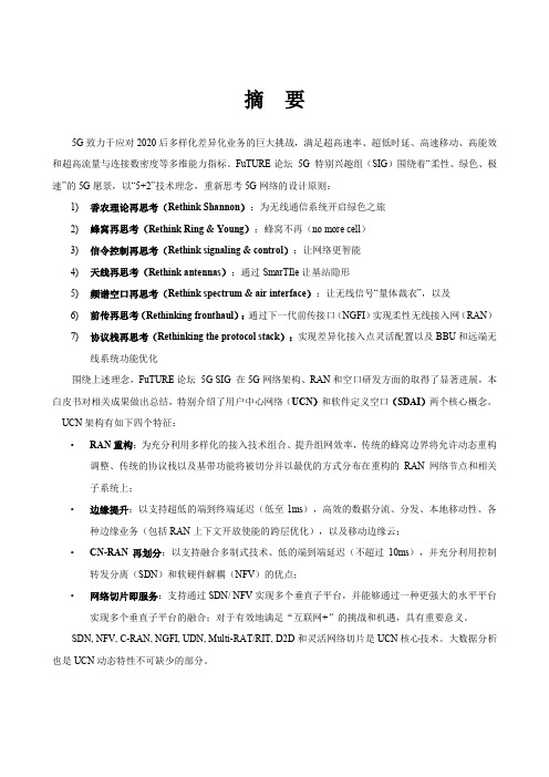
摘要5G致力于应对2020后多样化差异化业务的巨大挑战,满足超高速率、超低时延、高速移动、高能效和超高流量与连接数密度等多维能力指标。
FuTURE论坛5G 特别兴趣组(SIG)围绕着“柔性、绿色、极速”的5G愿景,以“5+2”技术理念,重新思考5G网络的设计原则:1)香农理论再思考(Rethink Shannon):为无线通信系统开启绿色之旅2)蜂窝再思考(Rethink Ring & Young):蜂窝不再(no more cell)3)信令控制再思考(Rethink signaling & control):让网络更智能4)天线再思考(Rethink antennas):通过SmarTIle让基站隐形5)频谱空口再思考(Rethink spectrum & air interface):让无线信号“量体裁衣”,以及6)前传再思考(Rethinking fronthaul):通过下一代前传接口(NGFI)实现柔性无线接入网(RAN)7)协议栈再思考(Rethinking the protocol stack):实现差异化接入点灵活配置以及BBU和远端无线系统功能优化围绕上述理念,FuTURE论坛5G SIG 在5G网络架构、RAN和空口研发方面的取得了显著进展,本白皮书对相关成果做出总结,特别介绍了用户中心网络(UCN)和软件定义空口(SDAI)两个核心概念。
UCN架构有如下四个特征:•RAN重构:为充分利用多样化的接入技术组合、提升组网效率,传统的蜂窝边界将允许动态重构调整、传统的协议栈以及基带功能将被切分并以最优的方式分布在重构的RAN网络节点和相关子系统上;•边缘提升:以支持超低的端到终端延迟(低至1ms),高效的数据分流、分发、本地移动性、各种边缘业务(包括RAN上下文开放使能的跨层优化),以及移动边缘云;•CN-RAN再划分:以支持融合多制式技术、低的端到端延迟(不超过10ms),并充分利用控制转发分离(SDN)和软硬件解耦(NFV)的优点;•网络切片即服务:支持通过SDN/ NFV实现多个垂直子平台,并能够通过一种更强大的水平平台实现多个垂直子平台的融合;对于有效地满足“互联网+”的挑战和机遇,具有重要意义。
发布《CTNet2025网络架构白皮书》说干就干,
发布《CTNet2025网络架构白皮书》说干就干,作者:赵妍来源:《通信产业报》2016年第26期近日,中国电信发布转型新战略,明确综合智能信息服务运营商定位,提出以智能为牵引,实施网络、业务、运营、管理四大重构。
网络作为运营商的最大核心资源,也是实现中国电信战略转型的主要抓手。
7月11日,中国电信集团发布《中国电信CTNet2025网络架构白皮书》(以下简称《白皮书》),全面启动网络智能化重构。
《白皮书》的发布,标志着中国电信正式进入转型新战略的实施阶段。
网络重构启动为了适应互联网新时代的大环境,更好地生存和发展,运营商必须对现有网络架构进行重构,从而在根本上改造网络的特征,改善网络的能力,改进网络的服务。
为此,《白皮书》详细说明了中国电信的目标网络架构。
中国电信的目标网络应具备如下四个新特征。
(1)简洁:网络的层级、种类、类型、数量和接口应尽量减少,降低运营和维护的复杂性和成本。
(2)敏捷:网络提供软件编程能力,资源具备弹性的可伸缩的能力,便于网络和业务的快速部署和保障。
(3)开放:网络能够形成丰富、便捷的开放能力,主动适应互联网应用所需。
(4)集约:网络资源应能够统一规划、部署和端到端运营,改变分散、分域情况下高成本、低效率的状况。
伴随着上述特征的实现,中国电信将进一步为客户提供“可视”、“随选”、“自服务”的网络能力,提升用户体验。
其中,网络可视是指,面向客户,提供基于应用的网络资源视图;资源随选是指面向业务,提供按需、自动化的网络资源部署;用户自服务是指,面向服务,提供基于客户网络的自助管理。
灵活适应互联网应用。
中国电信以SDN/NFV为技术抓手,以网元云化部署、软件定义网络智能控制、部署新一代运营系统、网络DC化改造等为网络切入点,推进网络的纵向解耦、横向打通。
重构路线图发布中国电信发布网络智能化重构路线图,网络演进分近期(2016-2019年)和中远期(2020-2025年)两阶段,两阶段任务均包括网络云化、新老协同/能力开放两方面任务。
5G同步组网架构及关键技术白皮书
基于现有1588v2优化实现高精度同步传输
优化1588v2实现高精度同步传输
✓ 打戳位置尽量靠近物理接口,尽量减少光模块内部的半静态延时 误差和动态延时误差;
✓ 提升打戳精度,提升打戳采样时钟的频率,或者采用其他方法提 升打戳分辨率;
✓ 改进同步算法,提升系统RTC同步精度; ✓ 加强模块间协同,提升系统内部RTC之间(如接口卡和时钟卡)
频段
Sub 6G
Above 6G
子载波间隔(kHz) 15
30
60 60 120
TGP(us)
71.4 71.4 单符号 2符号
TBS, on-off (us) TBS, off-on (us)
TSync (us)
Tprop,BS1-BS2(us)
10 10 3
<22.7
10 10 3
<22.7
71.4 4符号
《5G同步组网架构及关键技术白皮书》
IMT-2020(5G)推进组 5G承载工作组 胡昌军
提纲
一、5G同步需求 二、5G高精度时间同步组网模型 三、5G高精度同步关键技术 四、总结与展望
5G同步目的
5G频率同步:确保载波频率与标称频率一致 5G时间同步:不同基站空口信号时间对齐(即调制信号相位一致) 5G频率同步相对于现有无线通信系统并无明显变化,而时间同步则要求更加严格,本白
◼ 采用高精度同步传输技术实现高精度同步承 载。传输设备单节点时间同步精度应优于一 定的限值(例如,ITU-T G.8273.2规定类型 C和类型D的T-BC的时间误差在10ns量级甚 至更小);
◼ 一般通过实现相对于UTC的绝对时间精度来 满足无线侧的相对时间精度要求。为了满足 两个AAU的无线空口参考点E之间的相对误 差(如3us),要求每个AAU无线空口输出 相对于UTC的绝对时间误差满足一定的限值 即可(如±1.5us)。
知识定义的意图网络白皮书
1前言1.1背景与驱动力目前网络的快速发展导致网络急剧复杂化和差异化,这一变化催生了对网络管控系统功能便捷性、多样性的更高要求。
这一要求本质上是对网络管控智能性的更高要求。
网络管控流程可以划分为网络感知、状态分析、意图输入与转译、策略生成、策略下发五个主要阶段。
4G网络中网络管控的主要流程由人工完成,AI等智能方法作为辅助工具,整个管控流程智能性较为初级。
网络进入5G时代,新的智能网元的引入在网络感知阶段和状态分析阶段实现了数据智能分析功能,有效推进网络管控流程的智能化程度。
预计在网络进入6G时代,网络管控流程中剩余阶段实现网络的自驱动,形成一个网络自智闭环。
除此之外,一个具有智能的网络,不但要能够完成对自身状态的理解和对自身性能的优化,更应当能够将这一系列知识传播出去,比如需要人员介入调控的时候恰到好处地理解需求、提供信息、评估和解决方案;又或者闭环状态下在不同网络之间交流知识,共同发展,完成网络的自我演进。
近年,意图网络(Intent-based Network,IBN)得到业界的普遍关注。
IBN的思想最早来自软件定义网络基于意图的北向接口,后来由Gartner于2017年正式提出[1]。
随着意图网络的引入,网络自治的发展目标逐步清晰,就是逐步实现网络的自规划、自适应、自优化、自管理、资源按需服务,最终达成“网随意动”。
其中,如何有效获取用户意图是关键难点,目前出现一些基于DSL(Domain-Specific Languages)设计的意图表示语言,都是通过一些关键字原语和表达语句来描述用户对网络的需求。
它的优点是可以在特定的环境下描述用户意图,得到的配置策略也具有很高的准确性。
它的缺点也很突出,并不是用户的自然语言表达,抽象级别仍然较低,需要向NLP方向演进。
同时,如何生成满足该需求的网络策略,还缺乏必要的智能性。
这也是实现网络自治,替代传统人工网络管控模式的关键。
另外,网络验证作为IBN的关键环节,发挥着不可或缺的重要作用。
《 G网络架构设计》白皮书
IMT-2020(5G)推进组5G网络架构设计白皮书目录引言P15G网络:挑战与机遇P25G网络架构设计P45G网络代表性服务能力P85G网络标准化建议P15总结和展望P17主要贡献单位P18IMT-2020(5G)推进组于2013年2月由中国工业和信息化部、国家发展和改革委员会、科学技术部联合推动成立,组织架构基于原IMT-Advanced推进组,成员包括中国主要的运营商、制造商、高校和研究机构。
推进组是聚合中国产学研用力量、推动中国第五代移动通信技术研究和开展国际交流与合作的主要平台。
IMT-2020(5G)推进组5G网络架构设计白皮书2IMT-2020(5G)推进组5G网络架构设计白皮书随着5G研究的全面展开并逐步深入,业界就环境,为不同用户和垂直行业提供高度可定制化5G场景形成基本共识:面向增强的移动互联网应的网络服务,构建资源全共享、功能易编排、业用场景,5G提供更高体验速率和更大带宽的接入务紧耦合的综合信息化服务使能平台。
能力,支持解析度更高、体验更鲜活的多媒体内5G国际标准化工作现已全面展开,需要尽容;面向物联网设备互联场景,5G提供更高连接快细化5G网络架构设计方案并聚焦关键技术方密度时优化的信令控制能力,支持大规模、低成向,以指导后续产业发展。
本白皮书从逻辑功能本、低能耗IoT设备的高效接入和管理;面向车和平台部署的角度,以四维功能视图的方式呈现联网、应急通信、工业互联网等垂直行业应用场了新型5G网络架构设计,并提炼了网络切片、移景,5G提供低时延和高可靠的信息交互能力,支动边缘计算、按需重构的移动网络、以用户为中持互联实体间高度实时、高度精密和高度安全的心的无线接入网和能力开放等5G网络代表性服务业务协作。
能力。
白皮书最后提出了5G网络架构和技术标准面对5G极致的体验、效率和性能要求,以及化工作的推进建议。
“万物互联”的愿景,网络面临全新的挑战与机遇。
5G网络将遵循网络业务融合和按需服务提供的核心理念,引入更丰富的无线接入网拓扑,提供更灵活的无线控制、业务感知和协议栈定制能力;重构网络控制和转发机制,改变单一管道和固化的服务模式;利用友好开放的信息基础设施1IMT-2020(5G)推进组5G网络架构设计白皮书1.极致性能指标带来全面挑战首先,为了满足移动互联网用户极致的视频在高吞吐量和大连接场景下容易导致流量过载和及增强现实等业务体验需要,5G系统提出了随时信令拥塞。
- 1、下载文档前请自行甄别文档内容的完整性,平台不提供额外的编辑、内容补充、找答案等附加服务。
- 2、"仅部分预览"的文档,不可在线预览部分如存在完整性等问题,可反馈申请退款(可完整预览的文档不适用该条件!)。
- 3、如文档侵犯您的权益,请联系客服反馈,我们会尽快为您处理(人工客服工作时间:9:00-18:30)。
IMT-2020(5G)推进组5G网络架构设计白皮书目录引言P15G网络:挑战与机遇P25G网络架构设计P45G网络代表性服务能力P85G网络标准化建议P15总结和展望P17主要贡献单位P18IMT-2020(5G)推进组于2013年2月由中国工业和信息化部、国家发展和改革委员会、科学技术部联合推动成立,组织架构基于原IMT-Advanced推进组,成员包括中国主要的运营商、制造商、高校和研究机构。
推进组是聚合中国产学研用力量、推动中国第五代移动通信技术研究和开展国际交流与合作的主要平台。
IMT-2020(5G)推进组5G网络架构设计白皮书2IMT-2020(5G)推进组5G网络架构设计白皮书随着5G研究的全面展开并逐步深入,业界就环境,为不同用户和垂直行业提供高度可定制化5G场景形成基本共识:面向增强的移动互联网应的网络服务,构建资源全共享、功能易编排、业用场景,5G提供更高体验速率和更大带宽的接入务紧耦合的综合信息化服务使能平台。
能力,支持解析度更高、体验更鲜活的多媒体内5G国际标准化工作现已全面展开,需要尽容;面向物联网设备互联场景,5G提供更高连接快细化5G网络架构设计方案并聚焦关键技术方密度时优化的信令控制能力,支持大规模、低成向,以指导后续产业发展。
本白皮书从逻辑功能本、低能耗IoT设备的高效接入和管理;面向车和平台部署的角度,以四维功能视图的方式呈现联网、应急通信、工业互联网等垂直行业应用场了新型5G网络架构设计,并提炼了网络切片、移景,5G提供低时延和高可靠的信息交互能力,支动边缘计算、按需重构的移动网络、以用户为中持互联实体间高度实时、高度精密和高度安全的心的无线接入网和能力开放等5G网络代表性服务业务协作。
能力。
白皮书最后提出了5G网络架构和技术标准面对5G极致的体验、效率和性能要求,以及化工作的推进建议。
“万物互联”的愿景,网络面临全新的挑战与机遇。
5G网络将遵循网络业务融合和按需服务提供的核心理念,引入更丰富的无线接入网拓扑,提供更灵活的无线控制、业务感知和协议栈定制能力;重构网络控制和转发机制,改变单一管道和固化的服务模式;利用友好开放的信息基础设施1IMT-2020(5G)推进组5G网络架构设计白皮书1.极致性能指标带来全面挑战首先,为了满足移动互联网用户极致的视频在高吞吐量和大连接场景下容易导致流量过载和及增强现实等业务体验需要,5G系统提出了随时信令拥塞。
随地提供100Mbps—1Gbps的体验速率的指标要第三,为了支持自动驾驶和工业控制等高求,甚至在500km/h的高速运动过程中,也要求度实时性要求的业务,5G系统需要在高可靠性具备基本服务能力和必要的业务连续性。
前提下,满足端到端毫秒级的极低时延要求。
现第二,为了支持移动互联网和物联网场网中,端到端时延和业务中断时间都在百毫秒量景设备高效接入的要求,5G系统需同时满足级,与5G时延要求存在两个数量级的差距,也难Tbps/km2的流量密度和百万/km2连接密度要以满足特定业务的可靠性和安全性要求。
求,而现有网络流量中心汇聚和单一控制机制体验速率移动性重要性:高极致体验重要性:中重要性:低流量密度时延极致效率极致性能可靠性连接密度全面网络挑战图1 5G全面的网络挑战2IMT-2020(5G)推进组5G网络架构设计白皮书2.网络与业务融合触发全新机遇丰富的5G应用场景对网络功能要求各异:从突管系统,垂直行业能够获得对网内终端和设备更丰发事件到周期事件的资源分配;从自动驾驶到低移富的监控和管理手段,全面掌控业务运行状况;利动性终端的移动性管理;从工业控制到抄表业务的用功能高度可定制化和资源动态可调度的5G基础设时延要求等。
面对如此多样化的业务场景,5G提出施能力,第三方业务需求方可以快捷的构建数据安的网络与业务深度融合,按需提供服务的新理念能全隔离和资源弹性伸缩的专用信息服务平台,从而为信息产业的各个环节带来全新的发展机遇。
降低开发门槛。
基于5G网络“最后一公里”的位置优势,互对于移动网络运营商而言,5G网络有助于进一联网应用服务提供商能够提供更具差异性的用户体步开源节流。
开源方面,5G网络突破当前封闭固化验。
例如,基于网络开放的位置区域、移动轨迹和的网络服务框架,全面开放基础设施、组网转发和无线环境等上下文信息,APP能够筛选出更恰当的控制逻辑等网络能力,构建综合化信息服务使能平服务参数,提升客户黏性;同时,利用网络边缘的台,为运营商引入新的服务增长点。
节流方面,按内容缓存和计算能力,服务提供商可以为指定用户需提供的网络功能和基础设施资源有助于更好的节提供更优质的时延和带宽服务质量保障,在竞争中能增效,降低单位流量的建设与运营成本。
占得先机。
需要指出的是,随着移动网络和互联网在业务基于5G网络“端到端全覆盖”的基础设施优方面融合的不断深入,两者在技术方面也在相互渗势,以垂直行业为代表的物联网业务需求方可以获透和影响。
云计算、虚拟化、软件化等互联网技术得更强大且更灵活的业务部署环境。
依托强大的网是5G网络架构设计和平台构建的重要使能技术。
图2 综合化信息服务使能平台3IMT-2020(5G)推进组5G网络架构设计白皮书5G网络架构设计包括系统设计和组网设计两提供按需的接入、移动性和会话管理,支持精个方面。
系统设计重点考虑逻辑功能实现以及不细化资源管控和全面能力开放;转发平面具备同功能之间的信息交互过程,构建功能平面划分分布式的数据转发和处理功能,提供更动态的更合理的统一的端到端网络逻辑架构。
组网设计锚点设置,以及更丰富的业务链处理能力。
聚焦设备平台和网络部署的实现方案,以充分发在整体逻辑架构基础上,5G网络采用模块化挥基于SDN/NFV技术的新型基础设施环境在组功能设计模式,并通过“功能组件”的组合,构建网灵活性和安全性方面的潜力。
满足不同应用场景需求的专用逻辑网络。
5G网络以1.5G系统设计:逻辑视图与功能视图控制功能为核心,以网络接入和转发功能为基础资源,向上提供管理编排和网络开放的服务,形成三如图3所示,5G网络逻辑视图由3个功能平面层网络功能视图,如图4所示,其中:构成:接入平面,控制平面和转发平面。
接入平面引入多站点协作、多连接机制和多制式融合技术,构建更灵活的接入网拓扑;控制平面基于可重构的集中的网络控制功能,图3 5G网络逻辑视图4IMT-2020(5G)推进组5G网络架构设计白皮书管理编排层:由用户数据、管理编排和能力的指示,在网络控制层中进行组合,实现对资源开放三部分功能组成。
用户数据功能存储用户签层的灵活调度。
约、业务策略和网络状态等信息。
管理编排功能网络资源层:包括接入侧功能和网络侧功基于网络功能虚拟化技术,实现网络功能的按需能。
接入侧包括中心单元(CU)和分布单元编排和网络切片的按需创建。
能力开放功能提供(DU)两级功能单元,CU主要提供接入侧的业对网络信息的统一收集和封装,并通过API开放务汇聚功能;DU主要为终端提供数据接入点,给第三方。
包含射频和部分信号处理功能。
网络侧重点实现网络控制层:实现网络控制功能重构及模块数据转发、流量优化和内容服务等功能。
基于分化。
主要的功能模块包括:无线资源集中分配、布式锚点和灵活的转发路径设置,数据包被引导多接入统一管控、移动性管理、会话管理、安全至相应的处理节点,实现高效转发和丰富的数据管理和流量疏导等。
上述功能组件按管理编排层处理,如深度包检测,内容计费和流量压缩等。
图4 5G网络功能视图5IMT-2020(5G)推进组5G网络架构设计白皮书2.5G组网设计:平台视图与组网视图线接入方案,并能完成接入网逻辑实体的实时动态的功能迁移和资源伸缩。
利用网络虚拟化技5G基础设施平台将更多的选择由基于通用术,可以实现RAN内部各功能实体动态无缝连硬件架构的数据中心构成支持5G网络的高性能转接,便于配置客户所需的接入网边缘业务模式。
发要求和电信级的管理要求,并以网络切片为实另外,针对RAN侧加速器资源配置和虚拟化平台例,实现移动网络的定制化部署。
间高速大带宽信息交互能力的特殊要求,虚拟化引入SDN/NFV技术(如图5所示),5G硬管理与编排技术需要进行相应的扩展。
件平台支持虚拟化资源的动态配置和高效调度,SDN/NFV技术融合将提升5G进一步组大在广域网层面,NFV编排器可实现跨数据中心的网的能力:NFV技术实现底层物理资源到虚拟功能部署和资源调度,SDN控制器负责不同层级化资源的映射,构造虚拟机(VM),加载网数据中心之间的广域互连。
城域网以下可部署单络逻辑功能(VNF);虚拟化系统实现对虚拟个数据中心,中心内部使用统一的NFVI基础设化基础设施平台的统一管理和资源的动态重配施层,实现软硬件解耦,利用SDN控制器实现数置;SDN技术则实现虚拟机间的逻辑连接,构据中心内部的资源调度。
建承载信令和数据流的通路。
最终实现接入网NFV/SDN技术在接入网平台的应用是业界和核心网功能单元动态连接,配置端到端的业聚焦探索的重要方向。
利用平台虚拟化技术,可务链,实现灵活组网。
以在同一基站平台上同时承载多个不同类型的无图5 5G网络平台视图6IMT-2020(5G)推进组5G网络架构设计白皮书如图6所示,一般来说,5G组网功能元素可接入级:包含无线接入网的CU和DU功能,分为四个层次:CU可部署在回传网络的接入层或者汇聚层;DU 中心级:以控制、管理和调度职能为核部署在用户近端。
CU和DU间通过增强的低时延心,例如虚拟化功能编排、广域数据中心互连和传输网络实现多点协作化功能,支持分离或一体BOSS系统等,可按需部署于全国节点,实现网化站点的灵活组网。
络总体的监控和维护。
借助于模块化的功能设计和高效的NFV/ 汇聚级:主要包括控制面网络功能,例如移SDN平台。
在5G组网实现中,上述组网功能元素动性管理、会话管理、用户数据和策略等。
可按部署位置无需与实际地理位置严格绑定,而是可需部署于省分一级网络。
以根据每个运营商的网络规划、业务需求、流量区域级:主要功能包括数据面网关功能,重优化、用户体验和传输成本等因素综合考虑,对点承载业务数据流,可部署于地市一级。
移动边不同层级的功能加以灵活整合,实现多数据中心缘计算功能、业务链功能和部分控制面网络功能和跨地理区域的功能部署。
也可以下沉到这一级。
图6 5G网络组网视图7IMT-2020(5G)推进组5G网络架构设计白皮书与4G时期相比,5G网络服务具备更贴近用户需求、定制化能力进一步提升、网络与业务深度融合以及服务更友好等特征,其中代表性的网络服务能力包括:网络切片、移动边缘计算、按需重构的移动网络、以用户为中心的无线接入网和网络能力开放。
网络切片网络切片是网络功能虚拟化(NFV)应用于商务设计实例编排运行管理共享功能专用功能1专用功能2专用功能1专用功能25G阶段的关键特征。