联动导杆课程设计说明书
摆动导杆机构课程设计
摆动导杆机构课程设计一、课程目标知识目标:1. 学生能理解并掌握摆动导杆机构的基本概念、工作原理及其在工程中的应用。
2. 学生能够描述摆动导杆机构的运动特性,包括运动轨迹、速度和加速度的变化规律。
3. 学生能够运用相关的数学知识,分析摆动导杆机构的几何关系,并解决实际问题。
技能目标:1. 学生能够运用CAD软件绘制摆动导杆机构的三维模型,并进行简单的运动仿真。
2. 学生能够通过实验或模拟,观察和分析摆动导杆机构的运动状态,提出并解决问题。
3. 学生能够运用所学知识,设计简单的摆动导杆机构,实现特定的运动要求。
情感态度价值观目标:1. 学生能够培养对机械运动的兴趣,增强对机械设计、制造等相关专业的认识和认同。
2. 学生通过小组合作完成课程任务,培养团队协作精神和沟通能力。
3. 学生能够认识到摆动导杆机构在生活中的应用,提高对科学技术的认识和尊重,激发创新意识。
课程性质:本课程为机械设计基础课程,旨在帮助学生建立摆动导杆机构的基本理论,培养其运用CAD软件进行设计和分析的能力。
学生特点:学生为高中二年级学生,具备一定的物理、数学基础,对机械运动有一定了解,但对摆动导杆机构的认识有限。
教学要求:结合学生特点,注重理论与实践相结合,充分运用现代教学手段,激发学生的学习兴趣,提高其动手能力和解决问题的能力。
将课程目标分解为具体的学习成果,便于教学设计和评估。
二、教学内容本课程教学内容主要包括以下几部分:1. 摆动导杆机构的基本概念:介绍摆动导杆机构的定义、分类及其在工程中的应用。
- 教材章节:第二章第一、二节- 内容:摆动导杆机构的类型、特点及应用实例。
2. 摆动导杆机构的工作原理:讲解摆动导杆机构的运动原理、运动关系及运动特性。
- 教材章节:第二章第三节- 内容:摆动导杆机构的运动分析、几何关系、速度和加速度的计算。
3. 摆动导杆机构的设计与CAD软件应用:学习如何使用CAD软件进行摆动导杆机构的设计与运动分析。
推动架课程设计说明书

推动架课程设计说明书一、概述推动架是机械设备中常见的一种机构,主要用于将动力传递给目标对象。
本次课程设计旨在让学生了解推动架的基本原理、设计方法及应用,培养学生的实践能力和创新思维。
二、设计任务1. 设计一款推动架,能够承受一定的负载,并具有良好的传递性能。
2. 确定推动架的结构形式、零部件材质及选型。
3. 完成推动架的图纸绘制及说明。
4. 对推动架的性能进行评估。
三、设计过程1. 确定推动架的结构形式:推动架的基本结构形式有单轴推动架、双轴推动架等,根据实际需求和条件,我们选择了单轴推动架作为设计对象。
2. 计算推动架的承载能力:根据推动架的受力情况,计算出最大承载能力,以确保其能够承受预期的负载。
3. 选择零部件材质:根据实际工况和成本考虑,我们选择了铝合金作为推动架的零部件材质。
4. 零部件设计及选型:根据推动架的结构形式和承载能力,进行零部件的设计和选型,包括连杆、轴承、支架等。
5. 图纸绘制及说明:完成推动架的图纸绘制,包括零件图、装配图及尺寸标注等,并编写相应的说明文档。
6. 性能评估:通过模拟实验和实际测试,对推动架的性能进行评估,确保其能够满足预期的使用要求。
四、图纸及说明1. 图纸:推动架装配图、连杆零件图、轴承零件图等。
2. 说明:包括推动架的结构形式、工作原理、零部件选型及装配注意事项等。
五、总结本次推动架课程设计,通过理论学习和实践操作相结合的方式,使学生深入了解了推动架的基本原理、设计方法及应用。
同时,也锻炼了学生的动手能力和创新思维,为其今后从事相关领域的工作打下了坚实的基础。
六、建议与改进1. 在设计过程中,可以适当增加一些虚拟仿真技术的应用,以提高设计的效率和准确性。
2. 在材料选择上,可以考虑使用更轻质的材料,如钛合金或高强度塑料,以进一步提高推动架的性能和效率。
3. 在图纸绘制和说明编写方面,可以更加注重细节和准确性,以提高图纸的可读性和理解性。
4. 可以增加一些实际案例的分析和讲解,以帮助学生更好地理解和应用所学知识。
3 说明书(联动线)operation manual

1 General Information1.1 IntroductionThe first chapter introduces the structure of this Operation Manual.Please note that this Operation Manual is based upon data which was current at the time it was published and that can be changed at any time without prior notification. YIWU LINKAGE MACHINERY CO., LTD retains the right to modify the systems without prior notification and provides no warranty of any kind for machines refurbished by other companies, previously supplied by the YIWU LINKAGE MACHINERY CO., LTD.Carefully read the 0peration Manual before switching on and operating the machine.The 0peration Manual will help you in becoming familiar with the machine and its proper use.This Manual contains important information on operating the machine safely, properly and economically.Carefully following the instructions will help you to avoid risk and increases the reliability and life time of the machine.This Operation Manual must be complemented with the local and the customers’ safety instructions.In addition the current national regulations on accident prevention and protection of the environment must be complied with.The Manual must be kept permanently on the machine site.Every person entrusted to work with the machine must read this Operation Manual and follow its instructions.The machine must be operated only by trained personnel.The machine must be maintained only by professionally skilled personnel.2 Before Operation2.1 Basic principleUse for intended purpose onlyThe machine is designed exclusively for processing paper.Use of the machine for any other purpose whatsoever constitutes improper use. YIWU LINKAGE MACHINERY CO., LTD accepts no responsibility for any damage resulting from such improper use. The risk resides with the user.The machine must only be used when in good working order, with due regard to the purpose for which it was designed, the safety and risk aspects and observing the Operation Manual! Any malfunction must be corrected immediately, in particular any that could affect safety.Proper use is understood to include compliance with the safety regulations in the Operation Manual and adherence to the maintenance and service conditions.2.2 Warranty noteNot using the suggested parts from YIWU LINKAGE MACHINERY CO., LTD may lead to damage and impaired operation. The warranty covering the complete machine and its operation does not apply if:· Non-genuine parts are used· Original parts are altered or the machine tampered without the approval of YIWU LINKAGE MACHINERY CO., LTD· The machine is not operated, cared for or maintained properlyWearing parts are not covered by the warranty.2.3 Organizational measuresThe Operation Manual must be kept permanently at the machine site in a designated place, ready to hand.In addition to the Operation Manual, the local general statutory and other binding regulations governing accident prevention and environmental protection are to be observed!Such regulations can for example refer to the handling of hazardous substances or the provision and/or wearing of personal protection clothing.organization, work procedures, and personnel delegation, are to be kept together with the Operation Manual.Personnel delegated to operate the machine must have read and fully understood the Operating Manual, particularly the chapter on safety, before starting work.Whilst the machine is in operation, the safety instructions must be observed. This applies in particular to personnel who only work on the machine occasionally e.g. for setting up and maintenance.3 Machine data3.1 Technical specificationsMachine No. LD-1020 production line of roller paper high speedflexography saddle stitchMachine type Printing packing machineSet up for format 4 pockets4-pockets production max. 12,000 book/hourmax. 960 mmReel widthmax. 580 mmReel diameter max. 1.500 mmReel weight max.max. 670 mmPrinting length(cylinder circumference)max. 300 mmCut of length for cross-cutter(unfolded)max. 500 mmmax. 300 mmNumber of cuts/ cross-cutter max. 720cut/minProgression 5 mmNumber of sheetsmax. 50 sheetmax. 5 sheetLayer thickness (unfolded) max. 5 mmOperating speed max. 220 m/minOperating cycle max. 50 cycle/min3.2 Machine overview01 Unwind Station03 Cross Cutter04 Overlapping Station05 Counting and Collecting06 Cover Infeeder07 Stitching Station08 Folding Station09 Spine Pressing Station10 Cutting and Trimming4 Machine Control and Control Panels4.1 Touch Screen-Display: Start screenPosition Function1 Key switch for set-up modeMachine can only be driven in inch mode from the portable control panel2 Select language3 Start touch screen displays for machine status and value changesFor information: To return to the start windows, press on the upper left side of the screen4.2 Touch Screen-Display: Main menuPosition Function1 Indication of the operating status2 Indication of paper web speed3 Press one of the fields to access a submenua: operating settingsb: check all of the lamps on the machinec: fault messag e→you can have the fault messages displayed hereFor information:To return to the start windows, press on the upper left side of the screen4.3 Touch Screen-Display: Operating settingsPosition Function1a Entering the maximum machine accelerationUse the ‘faster’ and ‘on’ keys to adjust the machine to the set speed. Touching the key calls uponentry field. Enter the machine speed in this field.1b Entering the minimum machine speed (auto ramp). Use the ‘slower’ and ‘on’ keys to adjust the machine to the set speed. Touching the key calls up an entry field. Enter the machine speed in thisfield.2 Suction for cross-cutter ON/OFF3 Web monitoring ON/OFF4 Stitching ON/OFF5 Stitching Set-up operation ON/OFF6 Suction for cutting station ON/OFF7 Enter the book count for the pile. When touching the field, a numeric key pad comes up.8 Counter stacker. Reset the space.4.4 Touch Screen-Display: fault message (1)Position FunctionThis window is only displayed when a machine fault occurs or when the ‘fault message’ key ispressed1 This icon appears on all screens and indicates what program menu level the operator is on2 Display of fault numbers and fault messages-to view more information about the fault, press the row directlyCaution:All fault messages are automatically deleted after a disturbance is eliminated4.5 Touch Screen-Display: fault message (2)Position Function1 Display of fault numbers and fault messages2 Location of faults on the main machine3 Recommendation for eliminating a disturbanceThe numbers indicate the operating equipment code part4 Change back to previous display ‘fault’4.6 Machine ON/OFF: Standard control panelPosition Function1 EMERGENCY STOPUse only in emergency situations2 Inching MODE3 STOP MACHINEExecutes a controlled run down of the machine (soft stop)4 INCREASE MACHINE SPEED5 REDUCE MACHINE SPEED6 START MACHINEProcedure: First press the warning button (7) then, within 10 seconds, press the inching key (2)and the start key (6) simultaneously7 WARNINGHaving started the machine up, run the main motor at low speed and check the web guide rollers and the tape tracks.The machine cannot be switched on until the button ‘warning’ (7) 1 to 3 seconds is pressed on any of the standard control panels. After a delay of 3 seconds independent from the warning time, the machine is set in motion by pressing both keys ‘start’ (6) and ‘jog’ (2) together.If this is not done within a release period of 10 second, the procedure must be restarted from the beginning with ‘Warning’, ‘Start’ and ‘Jog’.During the 10 second period, the machine can be jogged as often as required.The release period is restarted each time the button is tapped.The machine can be run up to any speed required using the buttons ‘Faster’ (4) and ‘Slower’ (5)The machine can be stopped normally with the button (3).The Emergency Off switch (1) may only be used:-to stop the running machine in case of emergency-to secure the stationary machine against inadvertent restarting4.7 Unwind stationPosition Function1 Stop MACHINEExecutes a controlled run down of the machine (soft stop)4.8 Printing towerPosition Function1 EMERGENCY STOPUse only in emergency situations.4.9 Air pressure switchPosition Function1 Adjustment of overlapping blast air.2 Main air ON/OFF4.10 Counting and collecting stationPosition Function1 To take off paper stacks:raise/lower the tape track directly behind the transport gripper4.11 Infeeder on the overlapping unitPosition Function1 Switching meter/min2 Infeeder ON/OFF4.12 Infeeder(2)Position Function2 Raise infeeder table3 Lower infeeder table4 Infeeder, Non-Stop-Operation (Option )4.13 Infeeder, blast airPosition Function1 Adjust blast air2 Adjust blast air for separation of paper clips3 Adjust vacuum for suction beltImportant note:For safe cover transport, adjust the vacuum pressure as low as possible4.14 Count stackerPosition Function1 EMERGENCY STOPUse only in emergency situations5 Synchronizing the machine after changing the cut lengthThe synchronization procedure is broken down into the following steps:5.1 Cross cutter1. Cut correction for right-angled cut2. Changing format gear3. Adjusting timing of the cut5.2 Overlapping1. Adjust overlapper fingers to the paper format2. Adjust overlapper carriage to the paper format5.3 Counting and collecting stationSynchronize the counting and collecting station5.4 Printer tower1. Circumferential register adjustment-ruling roller2. Lateral register adjustment-ruling roller3. Alignment of face and back printed image5.5 Cross cutterAdjusting printed image through by fine adjusting the cross-cutter5.6 Transport fingersNext adjust the following sub-assemblies for the new paper format1. Infeeder2. Stitching station3. Folding station5. Trimming station5.1 Cross cutter5.1.1 Correcting for right-angled cut1. Fig 1: Undo the screw (1)2. Adjust the cross-cutter (2) with the hexagonal screw driver3. Continue this correction until 2 cut sheets placed back to back are identical in size4. Secure the setting by lock screw (1)5. Carry out this correction each time the cut length is changed5.1.2 Changing format gear wheel2. Slacken off the belt (3) by turning the eccentr ic (1)3. Remove the three screws (4) and remove the format gear wheel (5)4. Fit the new gear wheel as shown in the gear wheel table5. Tighten the screws6. Tighten the belt (3) by turning the eccentric (1)7. Lock the setting by tightening the screw (2)5.1.3 Adjusting timing of the cut1. Fig 3: release the clamp (1)2. Set the timing of the cut by turning the cross cutter (2) in direction of web movement3. Lock the setting by tightening the clamp (1)LD-1020 OPERATION MANUAL5.2 Overlapping5.2.1 Adjusting overlapping fingers to format1. Fig. 4: release the clamping lever (1) and set the Overlapper carriage to the sheet size with the lever (2)2. Lock the setting by tightening the clamping lever (1)3. Run a cut sheet of paper into the overlapper in inch mode4. Stop the machine!5. Fig.5: Undo the screw (1) on the drive side6. Turn the overlapping shaft by hand until the gap between the leading edge of the following sheet of paper and the overlapper fingers is approx. 5 mm. (see Fig.6).NOTE: The following sheet must not touch the overlapper fingers.7. Lock the setting by tightening the screw (1).5.2.2 Adjusting overlapper carriage to format1. Run a sheet into the overlapper until its trailing edge is depressed by the overlapper fingers.2. Stop the machine!3. Fig. 7: Release the clamping lever (1)4. Adjust the overlapper carriage by turning the lever (2) until the leading edge of the paper is under the centre point of the brake rollers.5. Tighten the clamping lever (1)5.3 Counting and collecting station5.3.1 Synchronizing the counting and collecting station1. Run the machine on, in inch modeStop the machine as soon as the gripper is completely closed.2. Fig.8: Undo the screw (2) and slacken the drive belts (4) using the eccentric (3)3. Undo three screws here (1)4. Run the machine in inch mode until the 1st paper strip is placed on the separator fingers.5. Re-tighten these three screws (1)6. Tighten the drive belts (4) using the eccentric (3) Lock the eccentric by tightening the screw (2)5.4 Print tower5.4.1 Circumferential register adjustment-ruling roller1. Fig.9: Release the clamping lever (1)2. Rotate the ruling roller with the lever (2) until the required printed image is obtained3. Secure the setting with the clamping lever (1)4. The counter-pressure cylinder can be adjusted by a maximum of ±5.0mmNOTE : Mark (3) local in the central5.4.2 If the adjustment range is insufficient1. The following operations must be carried out on operator side and drive side2. “Stop” the machine!3. Fig. 10: Undo the clamping lever (1)4. Undo the screw5. Using the hand grips (3), lift the ruling roller (4) out of the toothed engagement with the counter-pressure cylinder6. Rotate the ruling roller by hand. Rotation per tooth=5.0mm5.4.3 Lateral register adjustment-ruling roller1. Fig.11: slightly loosen the screw (1) on operator side and drive side.2. Adjust the ruling roller (3) sideways using the hand grip (2) until the required printed image is obtainedLD-1020 OPERATION MANUAL 5.4.4 Adjusting the register on first form andperfecting (double-sided web printing)1. Fig.12: Undo the clamping lever (1)2. Using the star grip (2), bring the imagesinto register3. Secure the setting with the clamping lever (1)4. Register adjustment for front and backprinted image is max. ±20mm5.5 Cross cutter5.5.1 Adjusting printed image to cut of thecross-cutter-fine adjustment on the right side1. Fig.13: Release the clamp (1)2. Turn the star-shaped knob (2) until the cutlines up with the ruling as required. Themaximum adjustment range is 25mm.3. Lock the setting by tightening the clamp (1)5.6 Transport fingers1. Inch a paper set on to the conveyor sectionof the machine with the gripper of the countingand collecting station2. Stop the machine!3. Fig.14: The coupling (2) is located on the driveside level with the counting and collecting station4. Remove the screw (3)5. Turn the connection shaft (1) by hand in theedge of the paper set is 20mm away from the transport fingers.6. Fig.14: Replace the screw (3) into the coupling (2) and lightly tighten it.Note:If the tapped hole for the screw (3) is not fully visible in the coupling (2), the coupling must be turned slightly in the direction of machine rotation.6. Basic settings for the machine 6.1 Collecting and counting station1. Fig.1: The cam disks (2 and 3) must line up with the machine hole (1) and the marker hole of the machine side frame.2. Adjustment:-For adjustment use a metal rod (4) with 8mm diameter. Line up the marker hole (1) of cam disk (5) with the marker hole of machine side frame. -Release the clamps of the cam disks (2 and 3) -Line up the cam disks with the marker hole (1) -Push the metal rod (4) through all cam disks. -Tighten the clamps6.2 Stitching station1. Fig.2: Fully raise (top dead centre) the stitching headdrive in inch mode shown in the illustration2. Run the Rotarnock to 003. Fig.3: The cam disks (2 and 3) must line up withmarker hole (1)4. Adjustment:- For adjustment use a metal rod (4) with 8mm diameter - Release the clamps of the cam disks (2 and 3)- Line up the cam disks with the marker hole (1)- Push the metal rod (4) through all cam disks.- Tighten the clamps.6.3 Spine pressing station1. Fig. 4: Fully raise (top dead centre) the stitching headdrive in inch mode shown in the illustration2. Run the Rotarnock to 00LD-1020 OPERATION MANUAL 3. Release the drive shafts on the L side.4. Fig. 5: turn the drive shafts until the cam shaftsline up with t marker hole (3)5. Adjustment:- For adjustment use a metal rod with 8mm diameter- Release the clamps of the cam disks.- Line up the cam disks with the marker hole (3)- Push the metal rod through all cam disks.- Tighten the clamps.6.4 Position of the transport fingers1. Distance of the transport fingers from the edgeof the table plate beneath the stapling heads=370 mm(marker hole). The Rotarnock is now on 00 and lights up2. Adjustment:Fig.6: Run the machine until the Rotarncok lights up.Align the transport fingers with the markerhole (5) using the bolt (4)7. Unwind station7.1 Function descriptionThe objective of the unwind station is to accommodate paper reels and to feed the machine with paper at a preset tension. The paper web tension is kept constant by a system of dancer rollers and a hydraulically controlled brake system. The dancer roller system is accommodated in the print tower. A hydraulically operated brake caliper alters the position of the dancer rollers to regulate the web tension. The length of paper web in the dancer roller system also acts as a paper buffer in the event of the machine being stopped abruptly. The paper reels are held clear of the floor. The lift is effective using a hydraulic hand pump. The paper reels used are wound on cardboard cores. Two clamp heads support the reel. The diameter of the clamp heads is matched to the diameter of the paper reel cores. In order t compensate for the changing delivery angle of the web, a web deflector is arranged behind the dancer roller system in the print tower.7.2Notes on safety1. Risk of crushing!The new paper reels weigh up to 1,000 kg!2. Warning-risk of injury!Even spent reels can weigh up to 20 kg!All personnel authorized to change reels must wear safety shoes!3. When changing reels and drawing the web in by hand,the machine must be stationary and prevented from beinginadvertently switched back on!Press one of the red emergency stop buttons!7.3Residual risks1. Exercise extreme caution! Sharp edges! The edges of the paper web can inflict cuts! Keep well clear of the paperweb! Protect bare parts of the body with protective clothing!2. Exercise extreme caution! Risk of crushing injury! The paper guide rollers can inflict serious injury! Fingerscaught between paper web and guide rollers can be crushed! Never touch the paper web near the guide rollers whilst the machine is running.3. Exercise extreme caution! Risk of injury through crushing and impact. New paper reels should be prepared wellclear of the unwind station! Only splicing should be carried out in the unwind station! Unused and partially used paper reels, remove from the machine, should be prepared for storage well clear of the unwind station.4. Exercise extreme caution! Sharp knives! For paper cutting, only knives with automatically retracting blades mustbe used!5. Exercise extreme caution! Risk of crushing injury! As the space between paper reel and the floor is less than500mm, there is a risk of being crushed!6. Exercise extreme caution! Risk of crushing injury! When running the paper reel in, there is a risk of being crushedbetween the reel and the supports where the gap is less than 500mm!7. Exercise extreme caution! Risk of crushing injury! When loading or unloading paper reels, keep every part of thebody well clear of the chucks and the paper reel!8. Exercise extreme caution! Risk of crushing injury! When lowering the paper reel, always keep every part of thebody clear of the space between the paper reel and the floor! Always wear safety clothing (e.g. protective footwear)!9. Exercise extreme caution! Risk of crushing injury! The dancer roller zone may only be entered when the dancerroller is fully lowered!7.4Preparing and Feeding in the reel1. Fig.1: release the clamping (3) on the R-sideand L-side from machine2. Draw the clamping heads (1) apart to theirextreme limit with the screws (2)3. Centre the paper reel between the two supportarms so that, when mounted, it unwinds clockwise.4. Align the support arms with the centre of the reel:raise the support arms by a pumping action with the lever (4)Lower the support arms by opening the valve (5)5. Release the disk brake.6. Fig.1: Press the clamping heads into the reel core upto the stop, using the screws (2)7. Retighten the clamping lever (3)8. Tighten the clamping heads with the compressedair driver (accessory)Ensure that the clamping heads are not under pressure when tightened!9. Re-apply the disk brake.7.5Adjusting the diverting roller withan unevenly wound paper reel1.Unevenly wound paper reel causes=irregular web tensionResult: creasing and migration of the web from the machine centre 2. Fig.2: Adjust the diverting roller with the star-shaped knob (1)7.6 Compensating for paper curl1. Fig.3: Problems can arise due to curling of the paper,in particular downstream of the cross-cutter, causingproduction faults.2. In order to compensate for this curvature, the de-curlingbar is swung into the paper web.3. Fig.4: Release the clamping lever (1)4. Set the decurling bar into position with the lever (2),until those are appropriate for paper web behind the crosscutter straight on the transport tape.5. Lock the setting by tightening the clamping lever (1).Note: With reducing role diameters must the decurlingbar be readjusted7.7 Changing paper reels1. Fig.5: lower the support arms by opening the valve (1).2. Remove the old paper reel.3. Load the new reel as described at the beginning of this Chapter.4. Tear off both ends of the paper web at right angles.5. Connect the two ends with double-sided adhesive tape.6. Tighten the paper web up to the print tower by rotating the paper reel7. Apply the disk brake8. Allow the paper web to run slowly through the machine until the splices reach the collecting station. From this point onwards, the machine can be run at normal speed.8 Inking units8.1 Fluids (ink and cleaners) and accessories 8.1.1 General notesIf quality print results are to be obtained and premature wear avoided to the rubber rollers supplied and, when fitted, to the ceramic and chrome screen rollers, it is essential that the proper fluids and accessories as specified in the following chapters be used.It is essential that you contact your ink supplier well in advance in order to obtain advice on the selection and use of suitable fluids and accessories.Please make sure that you are in possession of the technical data sheets and notes on their application. Fluids include-Special inks for rubber ruling work, water dilutable -De-foaming agents-Cleaning agents, other thinnersAccessories include -Cleaning cloths-Containers for pouring inks8.1.2 Notes on the use of fluids (warning)Only use inks, cleaning media and other fluids which you have discussed and agreed with your ink supplier. The fluids must be demonstrably suitable for flexo print ruling.Other materials could result in unsatisfactory ruling results and / or damage to the rollers.Across the world, the widest variety of rubber is used. Every type of rubber will age with time; that also applies of course for the rubber rollers supplied. When in use, the surface of the roller changes within the first 4-6 months; it hardens a little, becomes smoother and less sensitive to the action of certain chemicals. For this reason, it cannot simply be assumed that new inks and other accessories that have been introduced on ‘old’ rollers can also be used on new ones.8.1.3 Fluids to be avoidedInks, water, de-foaming agents and other liquids-and most especially cleaners and thinners-must be free of the following chemical substances as their presence could lead to roller damage.a.esters, ketones, aromatic hydro carbonates and aliphatic hydro carbonates (e.g. fuels, grease, white spirit, aromatic solvents,acetone, acetic acid). Constituents in these liquids could cause welling of the rubber rollers. In addition, silicone and grease often prevent clean ink transfer.b.Chlorides. They can be contained both in tap water and in distilled water as well as in inks, in strong concentrations (﹥﹥ppm). Chlorides typically cause crevice corrosion, particularly on chromated anilox rollers.c.The water must not contain any oily substances and solid particles and must be more or less free of chlorine (in the lowerppm range).8.1.4 Types of inkLiquid concentrates are to be preferred as they are easier to handle. It is unlikely that problems will arise with these types of ink.Ink powders have the considerable disadvantage that they must be handled exactly in accordance with the manufacturer’s instructions. Even then, powder inks tend to form crystals; the ink unit and the rollers must be cleaned very often in order to avoid their being damaged. In our opinion, this disadvantage is not outweighed by the price advantage, when compared to liquid concentrates.Alcohol based inks, or inks mixed with alcohol with a flash point of less than 63o C, constitute a fire risk. It is crucial that local regulations and the manufacturer’s instructions in particular be followed faithfully. Warning: alcohol concentration above 10% can attack the plastic material in the inking system.8.1.5 Cleaning clothCloths must be lint-free, absorbent, tear resistant and oil-free. Other types of cloth will cause contamination.8.1.6 Recommendations on fluids and accessoriesInksSupplier: Jaenecke + Schneemann Druckfarben GmbHP.O. Box 3149, 30031 Hanover, GermanyTel: ++49 511 54 710, Fax: ++49 511 54 71 211Ruling ink: Ruling ink Group 14, red, blue, blackAdditional tints are available. The inks are supplied in fluid concentrated form (10/25 kg containers) and can be diluted with water to be strength requiredDe-foaming agent: De-foaming agent, No. 30 32 32Flexo print ink: Flexo print ink and blend Group 5/A in various colorsThe inks are supplied in concentrated form (10/25 kg containers) and can be diluted with water to be strength requiredCleaning agentsSupplier: Printing industry, drug stores, ink suppliersProduct: Chemically pure alcohol for cleaning rollers, the designation is : IPA (i.e. isopropyl alcohol)Product: Clear water or hot soapy water for cleaning the felt scrapers and for washing out the ink units and washing down the rollers.Accessories: Soft, lint-free cloths and clean plastic containersSupplier: Free choice8.1.7 Ink consumptionAs a rough estimate (approx. ±10%), the ink consumption can be calculated from the following (basis: paperweight 70/m2) Consumption of ready made up ink approx: 0.2 ml liquid per 400 m ruleExamples:Squares 5mm: 6L liquid per t paper (both sides), respectively0.2ml liquid per m2 paper (one sided)Rules 10mm: 1.5L liquid per t paper (both sides), respectively0.05ml liquid per m2 paper (one sided)Margin rule A4: 0.07L liquid per 1 paper (both sides)Mixing ratios ink, flexo print ink, water (you will still need to carry out your own tests)Ruling:Red, green: thick print 1 part ruling ink 5 parts watermedium print 1 part ruling ink 10 parts waterthin print 1part ruling ink 20 parts waterBlue, black: thick print 1 part ruling ink 4 parts watermedium print 1 part ruling ink 8 parts waterthin print 1 part ruling ink 20 parts waterCover printing:With ruling ink: thick print 1 part ruling ink 0 part watermedium print 1part ruling ink 1 part waterthin print 1 part ruling ink 2 parts waterwith flexo print ink: thick print 1 part ruling ink 2 parts watermedium print 1 part ruling ink 4 parts waterthin print 1 part ruling ink 7 parts water8.2 Paper8.2.1 Suitability for rulingGood ruling results depend not only on the correct choice of ruling ink and other fluids but also, and most especially, on the properties of the paper being ruled.It should be sufficiently strong, free of dust and smooth, and it must be sufficiently absorbent to take up ink.In Europe as a rule, paper weighing 70g/m2±10g/m28.3 Unpacking, transportation, installation, storage8.3.1 Transporting rollers/ avoiding indentationsWhen fitting or removing the rollers, it is important that the support bolts supplied be used. If transport slings are used, care must be taken to ensure that the rollers are not marked by indentations; severe indentations will not recover.8.3.2 Contact with rubber surfaceOnly permit suitably tolerant fluids to come into contact with the rubber surface.Avoid touching the surfaces with your bare hands; finger prints can leave grease marks which will reduce the quality of ink。
机械原理课程设计(步进输送机)
2011 机械原理课程设计说明书目录一.设计任务书◆ 1.1课程名称: 步进输送机构 (3)◆ 1.2运动要求和计算基本数据 (3)二.机构方案的选定◆ 2.1轨道平台的移动 (3)◆ 2.2下料机的设计 (4)三.主要机构的设计计算◆ 3.1导杆机构的杆长设计 (6)◆ 3.2运动循环图 (8)◆ 3.3凸轮机构设计 (8)◆ 3.4插板相连的四杆机构的设计 (10)◆ 3.5速度和加速度的分析与计算(图解法) (12)◆ 3.6速度和加速度的分析与计算(解析法) (24)四.收获体会、建议 (28)五.参考文献 (28)机械课程设计说明书一.设计任务书1.课程名称: 步进输送机构简图设计1.工作原理及工艺动作简述步进输送机是一种间歇输送工件的传送机械。
工件由料仓卸落到轨道上,滑架作往复直线运动。
滑架正行程时,通过棘钩使工件向前运动;滑架返回时,棘钩的弹簧被压下,棘钩从工件下面滑过,工件不动。
当滑架又向前运动时,棘钩又钩住下一个工件向前运动,从而实现工件的步进传送。
插板作带停歇的往复运动,可使工件保持一定的时间间隔卸落到轨道上。
2.运动要求和计算基本数据1)输送工件形状和尺寸如附图1所示。
输送步长H=830mm。
2)滑架工作行程平均速度为0.42m/s。
要求保证输送速度尽可能左右平均,行程速比系数K值为1.7。
3)滑架导轨水平线至安装平面的高度在1100mm以下。
4)电动机功率可选1.1KW,1400r/min左右(如Y90S-4)二.机构方案的选定1.轨道平台的移动我们组经过讨论运用了:1)采用曲柄摇杆机构 2)采用曲柄摇杆机构和摇杆滑块机构 3)采用齿轮与齿条的配合2.下料机构的设计(插板的移动)我们组经过讨论运用了:1)采用凸轮导杆机构 2)采用从动件盘形凸轮与摇杆机构的组合 3)采用四杆机构三.主要机构的设计计算1.导杆机构的杆长设计1)有关系数计算2)杆长计算图2.13.凸轮机构设计我们采用的是对心滚子推杆盘形凸轮机构。
机械原理课程设计说明书
4. 1) 2) 3)
4) 5) 6) 7) 5.
6.
方案一
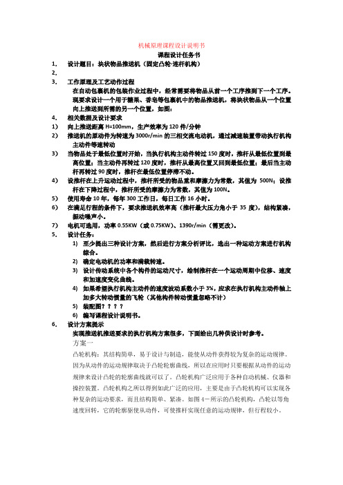
凸轮机构:其结构简单,易于设计与制造,能使从动件获得较为复杂的运动规律。 因为从动件的运动规律取决于凸轮轮廓曲线,所以在应用时只要根据从动件的运动 规律来设计凸轮的轮廓曲线就可以了。凸轮机构广泛应用于各种自动机械、仪器和 操控装置。凸轮机构之所以得到如此广泛的应用,主要是由于凸轮机构可以实现各 种复杂的运动要求,而且结构简单、紧凑。如图 4-所示的凸轮机构,凸轮以等角 速度回转,它的轮廓驱使从动件,可使推杆实现任意的运动规律,但行程较小。
缓和冲击, 吸收振动; (3) 过载时带与带轮间会出现打滑, 打滑虽然使传动失效, 但可防止损坏其他零件; (4)机构简单、成本低廉。 带传动的缺点: (1)传动的外廓尺寸较大; (2)需要张紧装置; (3)由于带 的滑动,不能保证固定不变的传动比;(4)带的寿命较短; (5)传动效率较低。 通常,带传动适用于中小功率的传动。目前 V 带传动应用最广,一般带速为 V=5≈25m/s,传动比 i≦7,传动效率 0.9 至 0.95.
摘要 我们小组设计的是包裹机包装作业过程中的块状物体推送机,其工作时要有固定的推 送行程和工作速度。我们所设计的结构是固定凸轮-连杆机构,由电动机驱动,完全由 机械结构控制实现工作要求,其工作状态稳定,效率高。本书对其设计过程做具体说 明,先对块状物体推送机的工作过程进行解析、研究,对设计要求做好全面分析,明 确设计方向;然后提出几组设计方案,对其进行分析比较,再提出总的设计方案;确 定方案后进行具体的设计,以使推送机的运动过程达到设计要求,主要包括各个构件 的尺寸大小和质量的确定,最后还要通过速度、加速度、各个构件的受力情况、压力 角等进行分析,进一步优化设计,达到减小功耗,稳定工作状态的目的。设计工作结 束后进行总结,将设计过程中遇到的问题进行总结,对设计作品做出评价。 目录 一、 课程设计任务书 设计题目 工作原理及工艺动作过程 相关数据及设计要求 设计任务 设计方案提示 二、 摘要 三、 目录 四、 课程设计题目简介 五、运动循环图 六、执行机构的选择和评价 七、机械传动系统设计计算 八、机械运动方案简图的绘制 九、机械运动系统机构的计算 十、机构运动分析
左摆动杠杆课程设计说明书

5切削用量、时间定额的计算
只算工序5的切削用量、时间定额
5.1切削用量的计算
5.1.1钻孔工步
1)背吃刀量 =14mm
2)进给量由表5-12,选取每转进给量f=0.2mm/r
3)切削速度由表5-22查得,因为工件为45号钢,v=20m/min,带入公式得
参照表4-15所列X51型立式机床的主轴转速取n=590r/min。实际转速为
查表2-28可得,精铰余量为Z精=0.15mm;扩孔的余量为Z扩=0.85mm;钻孔的余量为Z=14mm
查表1-20可确定各工序尺寸的加工精度等级为:精铰IT8;扩孔IT10;钻孔IT12
根据上述结果,查表2-40可知,个工步公差为:精铰, 15~ 15.027;扩孔,
14.85~ 14.92;钻孔 14~ 14.018
"mechanical Graphics" and "mechanical design",but also aexercise comprehensive use of ability.
Third.Enhance the ability of independent problem-solving and design capability
摇臂钻床
麻花钻铰刀
6
钻-粗铰-精铰孔6
摇臂钻床
麻花钻铰刀
7
钻-粗铰 盲孔
摇臂钻床
麻花钻铰刀
8
钻-粗铰-精铰孔15
摇臂钻床
麻花钻铰刀
9
粗铣-半精铣8mm槽
X51
铣刀铰刀
10
粗铣-半精铣2mm槽
X51
铣刀铰刀
11
去毛刺
课程设计说明书
课程设计说明书格式
一、课程设计说明书的内容
1.目录
2.设计任务书
3.导杆机构的运动分析及验算
4.导杆机构的动态静力分析及验算
5.飞轮设计
6.设计小结(本设计的优缺点、改进意见和课程设计的体会)
7.参考资料目录
二、课程设计说明书封面格式(A4幅面)
三、设计说明书书写示例(A4幅面)
四、其他要求
1.设计说明书要求论述清楚,文字精炼,计算准确,书写工整。
2.设计说明书用黑色或蓝色墨水笔按一定格式书写,采用统一格式的封面,装订成册
3.设计说明书其他格式要求,自行参考《机械原理课程设计指导书》。
插床导杆计算说明书
机械原理课程设计计算说明书§1 引言图1是插床机构的机构示意图。
该机构主要由导杆机构,凸轮机构和齿轮机构所组成。
导杆机构是由曲柄1,滑块2、5,导杆3,5连杆4和机架6所组成。
其中曲柄1为原动件。
当曲柄1以恒速1n 转动时,导杆3绕3O 轴来回摆动,通过连杆4,使装有刀具的滑块5沿导路y —y 作上下移动。
当滑块5沿导路向下移动时,刀具切削工件。
图1本人设计任务:设计方案8, 第3位置。
表1 插床导杆机构的设计指标 K H(mm) L6(mm) ξ n1(rpm) F(N) G3(N) 1.8 110 170 0.9 130 1100 170 G5(N) a(mm) b(mm) c(mm) d(mm) σ Js3(kgm ²) 33070601301400.050.21ϕ=0ϕ+90º=270º-2ψ+90º=360º-24286.51︒=334.2857º 1ω=6021n π=6013014159.32⨯⨯=13.6136 (rad/s )表中:K ——行程速度变化系数; H ——滑块5的冲程;6l =32o o l ——铰链中心2O 和3O 之间的距离;ξ=B o BC l l 3——杆长比;1n ——曲柄1的转速;F ——切削力;3G ——导杆3的重量; 5G ——滑块5的重量;σ——机器运转的不均匀系数;3s J ——导杆3对其质心轴的转动惯量;§2 插床导杆机构综合及运动分析一、已知条件行程速度变化系数K ,铰链中心2O 和3O 之间的距离6l ,滑块5的冲程H ,杆长比ξ,滑块5沿导路方向y —y 垂直于导杆3摆角ψ的分角线3O 2O ,并使导杆机构在整个行程中都能得到较小的压力角,曲柄转速1n 及指定的相对运动图解法的作业位置。
二、插床导杆机构的综合如图1所示,简记1l =A o l 2,3l =B o l 3,4l =BC l ,6l =32o o l ,h=3oo l 根据给定的已知条件,可按下列步骤确定插床导杆机构的有关尺寸 1)计算极位角θ及导杆摆角ψΨ=θ=180º11+-K K =180º18.118.1+-=51.4286º (1) 式中:K 为行程速度变化系数 2)求1l1l =6l 2sinψ=170sin24286.51︒=73.7602(mm ) (2) 式中:6l 为铰链中心2O 和3O 之间的距离 3)求3l , 4l3l =2sin2ψH =24286.51sin2110︒=126.7621 (mm) (3)式中:H 为滑块5的冲程4l =ξ3l =0.9⨯126.7621=114.0859 (mm ) (4)式中:ξ为杆长比 4)求h当滑块5的导路y —y 通过铰链中心B 的摆动弧'''B B 的绕度中点时,可使机构在整个行程中都能得到较小的压力角,故得:h=)2cos 1(213ψ+l =)24286.51cos 1(7621.12621︒+⨯⨯=120.4854 (mm ) (5)选取合适的长度比例尺l u =0.003(m/mm), 按指定的作业位置,正确地作出机构的运动简图。
推动架课程设计说明书
推动架课程设计说明书摘要:一、引言1.背景介绍2.课程设计的目的和意义3.课程设计的基本原则二、课程目标1.知识技能目标2.素质能力目标3.课程与专业的关系三、课程内容1.课程体系的构建2.课程模块的设计3.课程内容的更新与优化四、教学方法1.理论教学与实践教学相结合2.线上教学与线下教学相融合3.多元化教学手段的运用五、课程评价1.评价原则2.评价方法3.评价结果处理与应用六、课程实施与保障1.课程实施的具体措施2.课程资源的配置与利用3.课程质量监控与改进七、总结与展望1.课程设计的优势与创新2.课程实施的效果与反思3.课程未来的发展方向正文:一、引言随着我国教育事业的发展,架课程设计在高校课程体系中越来越受到重视。
本文旨在阐述一款推动架课程设计的说明书,从课程设计的目的、意义、原则等方面进行详细介绍,为高校教育工作者提供参考。
二、课程目标1.知识技能目标架课程设计旨在培养学生的专业知识和技能,使学生掌握架设计的基本原理、方法和技术,具备较强的实际操作能力。
2.素质能力目标通过课程学习,培养学生具有较强的创新意识、团队协作能力和良好的职业素养。
3.课程与专业的关系架课程设计与专业课程紧密结合,为学生提供丰富的实践机会,提高学生在实际工作中的应用能力。
三、课程内容1.课程体系的构建课程体系应涵盖架设计的基本理论、设计方法和实践操作等内容,形成科学、系统的课程体系。
2.课程模块的设计课程模块应包括:架设计原理、设计方法、材料选择、结构分析、制作工艺等,各模块之间相互关联,形成完整的课程体系。
3.课程内容的更新与优化根据行业发展需求,及时更新课程内容,优化教学资源,确保课程的实用性和前瞻性。
四、教学方法1.理论教学与实践教学相结合通过理论教学,使学生掌握专业知识;通过实践教学,提高学生的实际操作能力。
2.线上教学与线下教学相融合利用现代教育技术,实现线上教学与线下教学的优势互补,提高教学效果。
3.多元化教学手段的运用采用案例分析、分组讨论、项目实践等多种教学手段,激发学生的学习兴趣,提高学生的学习效果。
导杆机械加工课程设计
导杆机械加工课程设计一、课程目标知识目标:1. 理解导杆机械的基本结构、工作原理及加工流程;2. 掌握导杆机械加工过程中涉及的关键技术参数和工艺要求;3. 了解导杆机械加工领域的发展趋势及新技术应用。
技能目标:1. 能够运用CAD软件绘制导杆机械零件图,并进行简单的设计修改;2. 学会使用数控机床进行导杆机械零件的加工操作;3. 能够对加工过程中出现的问题进行分析和解决,提高加工精度和效率。
情感态度价值观目标:1. 培养学生热爱机械加工专业,树立正确的职业观;2. 增强学生的团队协作意识和沟通能力,培养合作共赢的精神;3. 培养学生严谨、细致的工作态度,提高对工程质量和安全的认识。
本课程针对高年级学生,结合导杆机械加工的实际情况,注重理论与实践相结合,培养学生的实际操作能力和解决问题的能力。
课程目标具体、可衡量,旨在帮助学生全面掌握导杆机械加工的相关知识,提高技能水平,同时培养良好的情感态度和价值观。
为确保教学效果,课程目标将分解为具体的学习成果,以便后续教学设计和评估。
二、教学内容1. 导杆机械基本结构及工作原理:- 导杆机械的分类及特点;- 导杆机械的工作原理及关键组成部分;- 导杆机械在工业生产中的应用。
2. 导杆机械加工工艺与关键技术参数:- 导杆机械加工的工艺流程;- 常用加工方法及适用范围;- 关键技术参数对加工质量的影响。
3. CAD软件在导杆机械设计中的应用:- CAD软件的基本操作;- 导杆机械零件图的绘制与修改;- 设计优化与工程图输出。
4. 数控机床操作与编程:- 数控机床的基本结构及功能;- 常用数控编程指令及其应用;- 导杆机械零件的数控加工操作。
5. 加工过程中的问题分析与解决:- 常见加工缺陷的产生原因及解决办法;- 加工误差分析与控制;- 提高加工精度和效率的措施。
6. 导杆机械加工新技术与发展趋势:- 现代制造技术在导杆机械加工中的应用;- 导杆机械加工领域的发展趋势;- 绿色制造与可持续发展。
- 1、下载文档前请自行甄别文档内容的完整性,平台不提供额外的编辑、内容补充、找答案等附加服务。
- 2、"仅部分预览"的文档,不可在线预览部分如存在完整性等问题,可反馈申请退款(可完整预览的文档不适用该条件!)。
- 3、如文档侵犯您的权益,请联系客服反馈,我们会尽快为您处理(人工客服工作时间:9:00-18:30)。
目录第一节联动导杆的工艺分析及生产类型的确定²²²²²²²²²²²²²²²²²²²²²²²²²²²1第二节确定毛坯、绘制毛坯图²²²²²²²²²²²²²²²²²²²²²²²²²²²²²²²²²²²²²²²²²2第三节拟定联动导杆工艺路线²²²²²²²²²²²²²²²²²²²²²²²²²²²²²²²²²²²²²²²²²3第四节确定加工余量和工序尺寸²²²²²²²²²²²²²²²²²²²²²²²²²²²²²²²²²²²²²²²8第五节确定切削用量²²²²²²²²²²²²²²²²²²²²²²²²²²²²²²²²²²²²²²²²²²²²²²²²11第六节联动导杆的加工工艺卡片²²²²²²²²²²²²²²²²²²²²²²²²²²²²²²²²²²²²²²13结束语²²²²²²²²²²²²²²²²²²²²²²²²²²²²²²²²²²²²²²²²²²²²²²²²²²²²²²²²²²²²²²²²13参考文献²²²²²²²²²²²²²²²²²²²²²²²²²²²²²²²²²²²²²²²²²²²²²²²²²²²²²²²²²²²²²14第一章联动导杆的机械加工工艺规程设计第一节联动导杆的工艺分析及生产类型的确定一、导杆的用途本次课程设计零件为一导杆,属轴类零件。
轴类零件是旋转体零件,其长度大于直径,一般由同心轴的外圆柱面、圆锥面、内孔和螺纹及相应的端面所组成。
导杆主要用来支承传动零部件,传递扭矩和承受载荷,故其广泛应用于各类机械产品中。
二、导杆的技术要求36HRC;孔Φ20要满足以中心轴线E (1)零件的材料为38Cr,其表面要求热处理30~为基准的对称度要求为0.1mm,垂直度要求为0.05mm;轴右端Φ18要满足以中心轴线E为基准的同轴度要求为Φ0.03mm;轴内螺纹孔4xM6-6H满足深度为8,以中心轴线D为基准的位置度要求满足Φ0.3mm;轴大端加工出C3倒角,轴小端加工出C2倒角。
Φ-mm的圆柱面对公共轴线的同轴度为Φ0.025mm;4⨯M6-6H对公共轴线(2)180025.0的位置度为Φ0.3mm;(3)该零件轴段的安排呈阶梯型,其加工精度要求较高,要有较高的形位公差,表面粗糙度最高达到了0.4µm,零件的中心轴是设计基准和工艺基准。
(4)通过对该零件图的绘制,知原图样的视图正确,尺寸、公差及技术要求齐全。
(5)该零件属于轴类零件,它的所有表面均需要切削加工,各个表面的加工精度和表面粗糙度都不难获得。
该零件除工作表面外,其余表面加工精度较低,通过车削,钻削等的一次加工就可以达到加工要求,主要工作表面虽然加工精度相对较高,但也在正常的生产条件下,采用较经济的方法保质保量的加工出来,由此可见,该零件的工艺性较好。
三、零件的工艺分析(1)零件的毛坯材料38Cr是典型的轴用材料,综合机械性能良好。
该材料是优质合金钢,经调制处理之后具有良好的力学性能和切削加工性能。
经淬火加高温回火后具有良好的综合力学性能,具有较高的强度、较好的韧性和塑性。
(2)根据表面粗糙度要求和生产类型,表面加工分为粗加工和精加工。
加工时应把精加工和粗加工分开,这样经多次加工以后逐渐减少了零件的变形误差。
(3)此零件的毛坯为模锻件,外形不需要加工。
(4)该轴的加工以车削为主,车削时应保证外圆的同轴度。
(5)在精车前安排了热处理工艺,以提高轴的疲劳强度和保证零件的内应力减少,稳定尺寸、减少零件变形,并能保证工件变形之后能在半精车时纠正。
(6)同一轴心线上各轴、孔的同轴度误差会导致轴承装置时歪斜,影响导杆的同轴度和使用寿命。
所以在车削磨削过程中,要保证其同轴度。
第二节确定毛坯、绘制毛坯图一、零件分析该零件材料为38Cr,考虑到车床在加工过程中要经常正反向旋转,该零件在加工过程中要承受载荷作用,因此选用锻件,以使金属纤维尽量不被切断,保证零件工作可靠。
假设为批量生产,零件的轮廓尺寸不大,故采用模锻成形来制造毛坯。
模锻成形后切边,进行调质,调质硬度合适,并进行酸洗,喷丸处理。
喷丸可以提高表面硬度,增加耐磨性,消除毛坯因脱碳而对机械加工带来的不利影响。
二、设计毛坯图导杆毛坯图见附图。
三、确定毛坯的毛坯尺寸、尺寸公差和机械加工余量参照课程设计指导教程第二章第二节确定模锻毛坯尺寸的公差和机械加工余量,查表2-6、表2-9首先确定如下各项因素:(1)公差等级由于导杆的用途和技术要求,确定该零件的公差等级为普通级。
(2)锻件质量Mt假设零件成品质量为1.5kg,估算锻件毛坯质量Mt=2.5kg。
(3)锻件形状复杂系数S对导杆零件图进行分析计算,可大致确定锻件外扩的长度、宽度、高度,则可计算出该导杆锻件的形状复杂系数S=Mt/Mn。
该锻件为长轴形,其最大直径为56mm,长255mm,估计该零件的形状复杂系数属S2级,即该锻件的复杂程度为一般。
(4)锻件材质系数由于该导杆材料为38Cr,38Cr表示含碳量为0.38%的合金结构钢,其中Cr平均含量<1.5%,故该锻件的材质系数为M1级。
(5)零件表面粗糙度由零件图可知,除孔Φ20、轴中部为0.8um,轴左端Φ40 、Ra=0.4um以外,其余加工表面Ra>=1.6um。
(6)确定机械加工余量根据锻件质量,零件表面粗糙度、形状复杂系数查表2-9,由此查得单边余量在厚度方向为1.7~2.2mm,水平方向为1.7~2.2mm,各轴向尺寸的单面余量为1.7~2.2mm,孔的单面加工余量查表2-10为2.0mm。
根据轴的尺寸长度与零件直径,查工艺手册得端面的加工余量为2mm。
第三节拟定导杆工艺路线一、定位基准的选择正确的选择定位基准是设计工艺过程中的一项重要的内容,也是保证加工精度的关键。
定位基准有精基准和粗基准之分,通常先确定精基准,然后确定粗基准。
(1)精基准的选择选择轴左端面端面500025.0Φ-和中间端面180025.0Φ-为精基准。
零件上的很多表面都可以以两端面作为基准进行加工。
可避免基准转化误差,也遵循基准统一原则。
两端的中心轴线是设计基准。
选用中心轴线为定为基准,可保证表面最后的加工位置精度,实现了设计基准和工艺基准的重合。
由于两轴面的精加工工序要求余量小且均匀,可利用其自身作为基准。
(2)粗基准的选择粗基准的选择应能保证加工面与非加工面之间的位置精度,合理分配各加工面的余量,为后续工序提供精基准。
所以为了便于定位、装夹和加工,可选轴的外圆表面为定为基准,或用外圆表面和顶尖孔共同作为定为基准。