养殖技术资料_12位-ad574a转换器中英文翻译资料
AD574A引脚图及应用电路图教学提纲

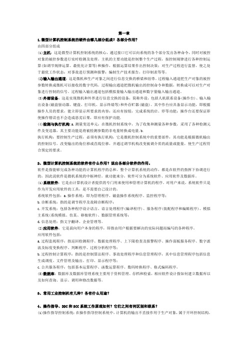
A D574A引脚图及应用电路图AD574A引脚图及应用电路图AD574A是美国模拟数字公司(Analog)推出的单片高速12位逐次比较型A/D 转换器,内置双极性电路构成的混合集成转换显片,具有外接元件少,功耗低,精度高等特点,并且具有自动校零和自动极性转换功能,只需外接少量的阻容件即可构成一个完整的A/D转换器,其主要功能特性如下:分辨率:12位非线性误差:小于±1/2LBS或±1LBS转换速率:25us 模拟电压输入范围:0—10V和0—20V,0—±5V和0—±10V两档四种电源电压:±15V和5V 数据输出格式:12位/8位芯片工作模式:全速工作模式和单一工作模式AD574A的引脚说明:[1]. Pin1(+V)——+5V电源输入端。
[2]. Pin2( )——数据模式选择端,通过此引脚可选择数据纵线是12位或8位输出。
[3]. Pin3( )——片选端。
[4]. Pin4(A0)——字节地址短周期控制端。
与端用来控制启动转换的方式和数据输出格式。
须注意的是,端TTL电平不能直接+5V或0V连接。
[5]. Pin5( )——读转换数据控制端。
[6]. Pin6(CE)——使能端。
[7]. Pin7(V+)——正电源输入端,输入+15V电源。
[8]. Pin8(REF OUT)——10V基准电源电压输出端。
[9]. Pin9(AGND)——模拟地端。
[10]. Pin10(REF IN)——基准电源电压输入端。
[11]. Pin(V-)——负电源输入端,输入-15V电源。
[12]. Pin1(V+)——正电源输入端,输入+15V电源。
[13]. Pin13(10V IN)——10V量程模拟电压输入端。
[14]. Pin14(20V IN)——20V量程模拟电压输入端。
[15]. Pin15(DGND)——数字地端。
[16]. Pin16—Pin27(DB0—DB11)——12条数据总线。
气体检测系统中英文对照外文翻译文献

⽓体检测系统中英⽂对照外⽂翻译⽂献中英⽂对照翻译研究智能⽓体检测系统⽂摘根据统计数据,中国近年来,煤⽓泄漏时有发⽣,对⼈⾝安全造成很⼤威胁,因此⽓体检测和监控系统是需要作为⼀个安全装置在家庭应⽤。
在本⽂中,智能⽓体检测系统的设计。
该检测仪采⽤单⽚机AT89S52为控制核⼼,采⽤催化燃烧式⽓体传感器元件MC112作为⽓体传感器(CH4)检测。
该系统的主要功能如下:浓度的实时监测CH4和显⽰的浓度值;发射声光报警信号,如果CH4浓度值超过报警值通过键盘⾯板输⼊;串⾏通信⼝发送数据地⾯以上主机。
软件调试和硬件仿真上述系统也实现在同⼀时间。
关键词:数据采集,传感器,串⾏通信,单⽚机。
在本⽂中,检测系统采⽤单⽚机作为控制计算机;整个系统的⽰意图如图1所⽰。
选择理由:单⽚机作为控制核⼼,它具有体积⼩尺⼨,⾼可靠性,低价格,使其成为⾏业使⽤⾮常合适智能仪表、实时控制领域。
系统的操作界⾯如图2所⽰。
在右上⾓号码显⽰默认的或⽤户定义的⽓体浓度值,在左上⾓显⽰检测到的⽓体浓度值。
报警灯的设置。
所有的功能通过设置控制⾯板上的按键控制,包括电源键,复位键,数据采集的关键。
其他键包括⼗个数字键,调整值键和回车键来改变阈值。
基本操作程序如下:⾸先按下电源键,系统初始化机数据采集的关键,LED在右上⾓显⽰的阈值1;⽤户可以定制阈值调整值的按键和数字键,然后按回车键确认更改。
系统开始检测⽓体浓度和上显⽰这些参左叶⾯积,同时实时数据的传输,通过RS-485总线主机地⾯上的。
3⽓体检测系统的硬件系统设计主要包括主控单元系统的硬件结构,传感器和信号放⼤电路,A/D转换模块,声光报警电路,键盘显⽰模块,串⼝通信模块。
3.1主控单元具有集成度⾼,体积⼩,价格低,单⽚机已⼴泛应⽤于⼯业过程中⼴泛应⽤包括控制,数据采集,机电⼀体化,智能仪表,家⽤电器和⽹络技术,以及显著提⾼的程度技术和⾃动化。
考虑在芯⽚选择两个因素,⼀是抗⼲扰的能⼒,提⾼单⽚机应⽤系统的⼲扰,图2. 系统运⾏界⾯图所以单⽚机必须有较⾼的外界⼲扰;⼆是单⽚机的性能价格⽐。
计算机控制技术课程设计-电阻炉温度控制系统设计

合肥工业大学《计算机控制技术》课程设计——电阻炉温度控制系统设计学院专业姓名学号_______ ________ _完成时间摘要:电阻炉的类型根据其热量产生的方式不同,可分为间接加热式和直接加热式两大类。
间接加热式电阻炉,就是在炉子内部有专用的电阻材料制作的加热元件,电流通过加热元件时产生热量,再通过热的传导、对流、辐射而使放置在炉中的炉料被加热。
直接加热式电阻炉,是将电源直接接在所需加热的材料上,让强大的电流直接流过所需加热的材料,使材料本身发热从而达到加热的效果。
工业电阻炉,大部分采用间接加热式,只有一小部分采用直接加热式。
由于电阻炉具有热效率高、热量损失小、加热方式简单、温度场分布均匀、环保等优点,应用十分广泛.关键词:炉温控制;高效率;加热一、总体方案设计本次课程设计主要就是使用计算机以及相应的部件组成电阻炉炉温的自动控制系统,从而使系统达到工艺要求的性能指标。
1、设计内容及要求电阻加热炉用于合金钢产品热力特性实验,电加热炉用电炉丝提供功率,使其在预定的时间内将炉内温度稳定到给定的温度值。
在本控制对象电阻加热炉功率为8KW,有220V交流电源供电,采用双向可控硅进行控制。
2、工艺要求及要求实现的基本功能本系统中所选用的加热炉为间接加热式电阻炉,控制要求为采用一台主机控制8个同样规格的电阻炉温度;电炉额定功率为20 kW;)恒温正常工作温度为1000℃,控温精度为±1%;电阻炉温度按预定的规律变化,超调量应尽可能小,且具有良好的稳定性;具有温度、曲线自动显示和打印功能,显示精度为±1℃;具有报警、参数设定、温度曲线修改设置等功能。
3、控制系统整体设计电阻炉温度计算机控制系统主要由主机、温度检测装置、A/D转换器、执行机构及辅助电路组成.系统中主机可以选用工业控制计算机、单片微型计算机或可编程序控制器中的一种作为控制器,再根据系统控制要求,选择一种合理的控制算法对电阻炉温度进行控制。
微型计算机控制技术第二版课后习题答案_潘新民
第一章1.微型计算机控制系统的硬件由哪几部分组成?各部分作用?由四部分组成(1)主机:这是微型计算机控制系统的核心,通过接口它可以向系统的各个部分发出各种命令,同时对被控对象的被控参数进行实时检测及处理。
主机的主要功能是控制整个生产过程,按控制规律进行各种控制运算(如调节规律运算、最优化计算等)和操作,根据运算结果作出控制决策;对生产过程进行监督,使之处于最优工作状态;对事故进行预测和报警;编制生产技术报告,打印制表等等。
(2)输入输出通道:这是微机和生产对象之间进行信息交换的桥梁和纽带。
过程输入通道把生产对象的被控参数转换成微机可以接收的数字代码。
过程输出通道把微机输出的控制命令和数据,转换成可以对生产对象进行控制的信号。
过程输入输出通道包括模拟量输入输出通道和数字量输入输出通道。
(3)外部设备:这是实现微机和外界进行信息交换的设备,简称外设,包括人机联系设备(操作台)、输入输出设备(磁盘驱动器、键盘、打印机、显示终端等)和外存贮器(磁盘)。
其中作台应具备显示功能,即根据操作人员的要求,能立即显示所要求的内容;还应有按钮,完成系统的启、停等功能;操作台还要保证即使操作错误也不会造成恶劣后果,即应有保护功能.(4)检测与执行机构:a.测量变送单元:在微机控制系统中,为了收集和测量各种参数,采用了各种检测元件及变送器,其主要功能是将被检测参数的非电量转换成电量.b.执行机构:要控制生产过程,必须有执行机构,它是微机控制系统中的重要部件,其功能是根据微机输出的控制信号,改变输出的角位移或直线位移,并通过调节机构改变被调介质的流量或能量,使生产过程符合预定的要求。
2、微型计算机控制系统的软件有什么作用?说出各部分软件的作用。
软件是指能够完成各种功能的计算机程序的总和。
整个计算机系统的动作,都是在软件的指挥下协调进行的,因此说软件是微机系统的中枢神经。
就功能来分,软件可分为系统软件、应用软件及数据库。
(1)系统软件:它是由计算机设计者提供的专门用来使用和管理计算机的程序。
AD574中文资料

12位A/D转换器AD574及其接口电路深圳中源单片机发展工作室AD574A是美国模拟数字公司(Analog)推出的单片高速12位逐次比较型A/D转换器,内置双极性电路构成的混合集成转换显片,具有外接元件少,功耗低,精度高等特点,并且具有自动校零和自动极性转换功能,只需外接少量的阻容件即可构成一个完整的A/D转换器,其主要功能特性如下:分辨率:12位非线性误差:小于±1/2LBS或±1LBS转换速率:25us模拟电压输入范围:0—10V和0—20V,0—±5V和0—±10V两档四种电源电压:±15V和5V数据输出格式:12位/8位芯片工作模式:全速工作模式和单一工作模式AD574A的引脚说明:[1]. Pin1(+V)——+5V电源输入端。
[2]. Pin2()——数据模式选择端,通过此引脚可选择数据纵线是12位或8位输出。
[3]. Pin3()——片选端。
[4]. Pin4(A0)——字节地址短周期控制端。
与端用来控制启动转换的方式和数据输出格式。
须注意的是,端TTL电平不能直接+5V或0V连接。
[5]. Pin5()——读转换数据控制端。
[6]. Pin6(CE)——使能端。
现在我们来讨论AD574A的CE、、、和A0对其工作状态的控制过程。
在CE=1、=0同时满足时,AD574A才会正常工作,在AD574处于工作状态时,当=0时A/D转换,当=1是进行数据读出。
和A0端用来控制启动转换的方式和数据输出格式。
A0-0时,启动的是按完整12位数据方式进行的。
当A0=1时,按8位A/D转换方式进行。
当=1,也即当AD574A处于数据状态时,A0和控制数据输出状态的格式。
当=1时,数据以12位并行输出,当=0时,数据以8位分两次输出。
而当A0=0时,输出转换数据的高8位,A0=1时输出A/D转换数据的低4位,这四位占一个字节的高半字节,低半字节补零。
养猪技术术语中英文

– 活体背膘厚、眼肌面积等
Back fat thickness, Loin eye muscle area
– 采食量、饲料利用率、生长速度等
Feed intake, Feed efficiency , Growth rate
• 遗传评估:动物模型BLUP
Genetic Evaluation: Animal model BLUP
• 分子标记辅助选择
Marker-assisted selection (MAS)
5
1.良种繁育 Genetic improvement • 联合育种或公司育种: 组建超级育种核心群,利用 遗传资源共享、扩大性能测定规模与统一遗传评 估 • Joint Breeding or Breeding Companies: set up a super nucleus population, share genetic resources, largescale of performance testing and genetic evaluation – 全国猪联合育种协作组、温氏 National swine breeding collaboration group Wen’s Company
4
1.良种繁育 Genetic improvement • 性能测定: 超声波技术、种猪自动饲喂系统
Performance testing: Ultrasonic technology (B-mode ultrasound ), Automatic feeding system(ACEMA, FIRE)
6
1. 良种繁育 Genetic improvement • 猪种资源的保护与利用 Protection and utilization of pig breed resources:
微型计算机控制技术第二版课后习题答案独立整理版-潘新民
第二章6 采样-保持器有什么作用?说明保持电容大小对数据采集系统的影响。
答:为了提高模拟量输入信号的频率范围,以适应某些随时间变化较快的信号的要求,可采用带有保持电路的采样器,即采样保持器。
保持电容对数据采集系统采样保持的精度有很大影响。
保持电容值小,则采样状态时充电时间常数小,即保持电容充电快,输出对输入信号的跟随特性好,但在保持状态时放电时间常数也小,即保持电容放电快,故保持性能差;反之,保持电容值大,保持性能好,但跟随特性差。
7 在数据采样系统中,是不是所有的输入通道都需要加采样-保持器,为什么?答:并不是所有的模拟量输入通道都需要采样保持器的,因为采样保持器是为了防止在A/D转换之前信号就发生了变化,致使A/D转换的结果出错,所以只要A/D转换的时间比信号变化的时间短就不需要。
8 采样频率的高低对数字控制系统有什么影响?举出工业控制实例加以说明?9 A/D和D/A转换器在微型计算机控制系统中有什么作用?答:答:A/D的作用主要是把传感器检测到的模拟电信号转换为数字电信号,方便用于单片机中进行处理。
D/A的作用,在单片机处理完毕的数字量,有时需要转换为模拟信号输出,D/A的作用正是用于把数字信号转换为模拟信号。
10 A/D转换器转换原理有几种?他们各有什么特点和用途?答:逐次逼近型,分辨率高,误差较低,转换速度快,应用十分广泛;双积分型:性能比较稳定,转换精度高,抗干扰能力强,电路较简单,工作速度低,多用于对转换精度要求较高,对转换速度要不高的场合,如数字电压表等检测仪器中,用的十分普遍。
并联比较型:转换速度快,精度高,但使用的比较器和触发器多,适用于速度高,精度要求不高的场合。
11 说明逐次逼近型A/D转换器的转换原理。
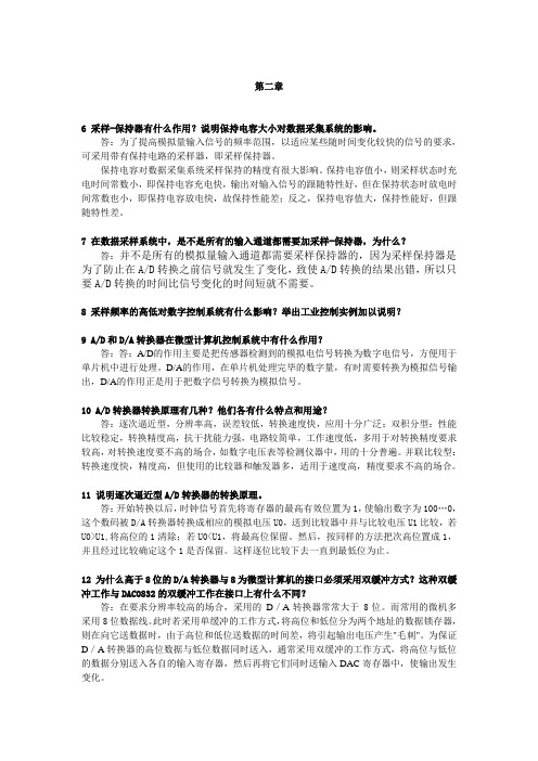
答:开始转换以后,时钟信号首先将寄存器的最高有效位置为1,使输出数字为100…0,这个数码被D/A转换器转换成相应的模拟电压U0,送到比较器中并与比较电压U1比较,若U0>U1,将高位的1清除;若U0<U1,将最高位保留。
南美对虾养殖英文文献

南美对虾养殖英文文献Farming of South American prawns has become a booming industry, with its sustainable practices gaining global attention.The unique ecosystem of South America provides an ideal environment for the cultivation of these crustaceans, ensuring their natural growth and health.Technological advancements have played a crucial role in the efficiency and success of prawn farming, with innovations in hatchery systems and disease management.Moreover, the economic benefits of prawn farming extend beyond the industry itself, contributing to local employment and community development.Environmental considerations are paramount, with efforts made to minimize the impact on surrounding habitats and to promote biodiversity.The demand for South American prawns is on the rise, driven by their high nutritional value and the growing awareness of their eco-friendly farming methods.Regulatory frameworks are in place to ensure the quality and safety of the prawns, meeting international standards and consumer expectations.Research is ongoing to explore new techniques for disease prevention and to enhance the nutritional content of the prawns, further elevating their market appeal.The future of South American prawn farming looks promising, with a focus on innovation, sustainability, and meeting the increasing global demand for this delectable seafood.。
- 1、下载文档前请自行甄别文档内容的完整性,平台不提供额外的编辑、内容补充、找答案等附加服务。
- 2、"仅部分预览"的文档,不可在线预览部分如存在完整性等问题,可反馈申请退款(可完整预览的文档不适用该条件!)。
- 3、如文档侵犯您的权益,请联系客服反馈,我们会尽快为您处理(人工客服工作时间:9:00-18:30)。
英文原文12-Bit A/D ConverterCIRCUIT OPERATIONThe AD574A is a complete 12-bit A/D converter which requires no external components to provide the complete successive approximation analog-to-digital conversion function. A block diagram of the AD574A is shown in Figure 1.Figure 1. Block Diagram of AD574A 12-Bit A-to-D ConverterWhen the control section is commanded to initiate a conversion (as described later), it enables the clock and resets the successiveapproximation register (SAR) to all zeros. Once a conversion cycle has begun, it cannot be stopped or restarted and data is not available from the output buffers. The SAR, timed by the clock, will sequence through the conversion cycle and return an end-of-convert flag to the control section. The control section will then disable the clock, bring the output status flag low, and enable control functions to allow data read functions by external command.During the conversion cycle, the internal 12-bit current output DAC is sequenced by the SAR from the most significant bit (MSB) to least significant bit (LSB) to provide an outputcurrent which accurately balances the input signal current through the 5kΩ(or10kΩ) input resistor. The comparator determines whether the addition of each successively-weighted bit current causes the DAC current sum to be greater or less than the input current; if the sum is less, the bit is left on; if more, the bit is turned off. After testing all the bits, the SAR contains a 12-bit binary code which accurately represents the input signal to within 1/2 LSB.The temperature-compensated buried Zener reference provides the primary voltage reference to the DAC and guarantees excellent stability with both time and temperature. The reference is trimmed to 10.00 volts 0.2%; it can s upply up to 1.5 mA to an external load in addition to the requirements of the reference input resistor (0.5 mA) and bipolar offset resistor (1 mA) when the AD574A is powered from 15 V supplies. If the AD574A is used with 12 V supplies, or if external cur rent must be supplied over the full temperature range, an external buffer amplifier is recommended. Any external load on the AD574A reference must remain constant during conversion. The thin-film application resistors are trimmed to match the full-scale output current of the DAC. There are two 5 k input scaling resistors to allow either a 10 volt or 20 volt span. The 10 k bipolar offset resistor is grounded for unipolar operation and connected to the 10 volt reference for bipolar operation.DRIVING THE AD574 ANALOG INPUTFigure 2. Op Amp – AD574A InterfaceThe output impedance of an op amp has an open-loop value which, in a closed loop, is divided by the loop gain available at the frequency of interest. The amplifier should have acceptable loop gain at 500 kHz for use with the AD574A. To check whether the outputproperties of a signal source are suitable, monitor the AD574’s input with an oscilloscope while a conversion is in progress. Each of the 12 disturbances should subside in sorless.For applications involving the use of a sample-and-hold amplifier, the AD585 is recommended. The AD711 or AD544 op amps are recommended for dc applications. SAMPLE-AND-HOLD AMPLIFIERSAlthough the conversion time of the AD574A is a maximum of 35 s, to achieve accurate 12-bit conversions of frequencies greater than a few Hz requires the use of a sample-and-hold amplifier (SHA). If the voltage of the analog input signal driving the AD574A changes by more than 1/2 LSB over the time interval needed to make a conversion, then the input requires a SHA.The AD585 is a high linearity SHA capable of directly driving the analog input of the AD574A. The AD585’s fast acquisition time, low aperture and low aperture jitter are ideally suited for high-speed data acquisition systems. Consider the AD574A converter with a 35 s conversion time and an input signal of 10 V p-p: the maximum frequency which may be applied to achieve rated accuracy is 1.5 Hz. However, with the addition of an AD585, as shown in Figure 3, the maximum frequency increases to 26 kHz.The AD585’s low output impedance, fast-loop response, and low droop maintain 12-bits of accuracy under the changing load conditions that occur during a conversion, making it suitable for use in high accuracy conversion systems. Many other SHAs cannot achieve 12-bits of accuracy and can thus compromise a system. The AD585 is recommended for AD574A applications requiring a sample and hold.Figure 3. AD574A with AD585 Sample and HoldSUPPLY DECOUPLING AND LAYOUTCONSIDERATIONSIt is critically important that the AD574A power supplies be filtered, well regulated, and free from high frequency noise. Use of noisy supplies will cause unstable output codes. Switching power supplies are not recommended for circuits attempting to achieve 12-bit accuracy unless great care is used in filtering any switching spikes present in the output. Remember that a few millivolts of noise represents several counts of error in a 12-bit ADC.Circuit layout should attempt to locate the AD574A, associated analog input circuitry, and interconnections as far as possible from logic circuitry. For this reason, the use of wire-wrap circuit construction is not recommended. Careful printed circuit construction is preferred.UNIPOLAR RANGE CONNECTIONS FOR THE AD574AThe AD574A contains all the active components required to perform a complete 12-bit A/D conversion. Thus, for most situations, all that is necessary is connection of the power supplies (+5 V, +12 V/+15 V and –12 V/–15 V), the analog input, and the conversion initiation command, as discussed on the next page. Analog input connections and calibration are easily accomplished; the unipolar operating mode is shown in Figure 4.Figure 4. Unipolar Input ConnectionsAll of the thin-film application resistors of the AD574A are trimmed for absolute calibration. Therefore, in many applications, no calibration trimming will be required. The absolute accuracy for each grade is given in the specification tables. For example, if no trims are used, the AD574AK guarantees 1 LSB max zero offset error and 0.25% (10 LSB) max full-scale error. (Typical full-scale error is 2 LSB.) If the offset trim is not required, Pin 12 can be connected directly to Pin 9; the two resistors and trimmer for Pin 12 are then not needed. If the full-scale trim is not needed, a 50 1% metal film resistor should be connected between Pin 8 and Pin 10.The analog input is connected between Pin 13 and Pin 9 for a 0 V to +10 V input range, between 14 and Pin 9 for a 0 V to +20 V input range. The AD574A easily accommodates an input signal beyond the supplies. For the 10 volt span input, the LSB has a nominal value of 2.44 mV; for the 20 volt span, 4.88 mV.If a 10.24 V range is desired (nominal 2.5 mV/bit), the gain trimmer (R2) should be replaced by a 50Ωesistor, and a 200Ω trimmer inserted in series with the analog input to Pin 13 for a full-scale range of 20.48 V (5 mV/bit), use a 500 trimmer into Pin 14. The gain trim described below is now done with these trimmers. The nominal input impedance into Pin 13 is 5kΩ, and 10kΩ into Pin 14.UNIPOLAR CALIBRATIONThe AD574A is intended to have a nominal 1/2 LSB offset so that the exact analog input for a given code will be in the middle of that code (halfway between the transitions to the codes above and below it). Thus, the first transition (from 0000 0000 0000 to 0000 0000 0001) will occur for an input level of +1/2 LSB (1.22 mV for 10 V range).If Pin 12 is connected to Pin 9, the unit will behave in this manner, within specifications. If the offset trim (R1) is used, it should be trimmed as above, although a different offset can be set for a particular system requirement. This circuit will give approximately 15 mV of offset trim range.The full-scale trim is done by applying a signal 1/2 LSB below the nominal full scale (9.9963 for a 10 V range). Trim R2 to give the last transition (1111 1111 1110 to 1111 1111 1111).BIPOLAR OPERATIONThe connections for bipolar ranges are shown in Figure 5. Again, as for the unipolar ranges, if the offset and gain specifications are sufficient, one or both of the trimmers shown can be replaced by a 50 1% fixed resistor. Bipolar calibration is similar to unipolar calibration.Figure 5. Bipolar Input ConnectionsCONTROL LOGICThe AD574A contains on-chip logic to provide conversion initiation and data readoperations from signals commonly available in microprocessor systems. Figure 6 shows the internal logic circuitry of the AD574A.The control signals CE, CS, and R/C control the operation of the converter. The state of R/C when CE and CS are both asserted determines whether a data read (R/C = 1) or a convert (R/C = 0) is in progress. The register control inputs AO and 12/8 control conversion length and data format. The AO line is usually tied to the least significant bit of the address bus. If a conversion is started with AO low, a full 12-bit conversion cycleis initiated. If AO is high during a convert start, a shorter 8-bit conversion cycle results. During data read operations, AO determines whether the three-state buffers containing the 8 MSBs of the conversion result (AO = 0) or the 4 LSBs (AO = 1) are enabled. The 12/8 pin determines whether the output data is to be organized as two 8-bit words (12/8 tied to DIGITAL COMMON) or a single 12-bit word (12/8 tied to VLOGIC). The 12/8 pin is not TTL-compatible and must be hard-wired to either VLOGIC or DIGITAL COMMON. In the 8-bit mode, the byte addressed when AO is high contains the 4 LSBs from the conversion followed by four trailing zeroes. This organization allows the data lines to be overlapped for direct interface to 8-bit buses without the need for external three-state buffers. It is not recommended that AO change state during a data read operation. Asymmetrical enable and disable times of the three-state buffers could cause internal bus contention resulting in potential damage to the AD574A.Figure 6. AD574A Control LogicAn output signal, STS, indicates the status of the converter. STS goes high at the beginning of a conversion and returns low when the conversion cycle is complete.TIMINGThe AD574A is easily interfaced to a wide variety of microprocessors and other digital systems. The following discussion of the timing requirements of the AD574A control signals should provide the system designer with useful insight into the operation of the device.Figure 7 shows a complete timing diagram for the AD574A convert start operation. R/C should be low before both CE and CS are asserted; if R/C is high, a read operation will momentarily occur, possibly resulting in system bus contention. Either CE or CS may be used to initiate a conversion; however, use of CE is recommended since it includes one less propagation delay than CS and is the faster input. In Figure 7, CE is used to initiate the conversion.Figure 7Once a conversion is started and the STS line goes high, convert start commands will be ignored until the conversion cycle is complete. The output data buffers cannot be enabled during conversion.Figure 8 shows the timing for data read operations. During data read operations, access time is measured from the point where CE and R/C both are high (assuming CS is already low). If CS is used to enable the device, access time is extended by 100 ns.Figure 8. Read Cycle TimingIn the 8-bit bus interface mode (12/8 input wired to DIGITAL COMMON), the address bit, AO, must be stable at least 150 ns prior to CE going high and must remain stable during the entire read cycle. If AO is allowed to change, damage to the AD574A output buffers may result.“STAND-ALONE” OPERATIONThe AD574A can be used in a ―stand-alone‖ mode, which is useful in systems with dedicated input ports available and thus not requiring full bus interface capability. In this mode, CE and 12/8 are wired high, CS and AO are wired low, and conversion is controlled by R/C. The three-state buffers are enabled when R/C is high and a conversion starts when R/C goes low. This allows two possible control signals—a high pulse or a low pulse. Operation with a low pulse is shown in Figure 11. In this case, the outputs are forced into the high impedance state in response to the falling edge of R/C and return to valid logic levels after the conversion cycle is completed. The STS line goes high 600 ns after R/C goes low and returns low 300 ns after data is valid.Figure 11. Low Pulse for R/C—Outputs Enabled After ConversionIf conversion is initiated by a high pulse as shown in Figure 12, the data lines are enabled during the time when R/C is high. The falling edge of R/C starts the next conversion, and the data lines return to three-state (and remain three-state) until the next high pulse of R/C.Figure 12. High Pulse for R/C—Outputs Enabled While R/C High, Otherwise High-ZUsually the low pulse for R/C stand-alone mode will be used. Figure 13 illustrates a typical stand-alone configuration for 8086 type processors. The addition of the 74F/S374 latches improves bus access/release times and helps minimize digital feedthrough to the analog portion of the converter.INTERFACING THE AD574A TO MICROPROCESSORSThe control logic of the AD574A makes direct connection to most microprocessor system buses possible. While it is impossible to describe the details of the interface connections for every microprocessor type, several representative examples will be described here.GENERAL A/D CONVERTER INTERFACECONSIDERATIONSA typical A/D converter interface routine involves several operations. First, a write to the ADC address initiates a conversion.The processor must then wait for the conversion cycle to complete, since most ADCs take longer than one instruction cycle to complete a conversion. Valid data can, of course, only be read after the conversion is complete. The AD574A provides an output signal (STS) which indicates when a conversion is in progress. This signal can be polled by the processor by reading it through an external three-state buffer (or otherinput port). The STS signal can also be used to generate an interrupt upon completion of conversion, if the system timing requirements are critical (bear in mind that the maximum conversion time of the AD574A is only 35 microseconds) and the processor has other tasks to perform during the ADC conversion cycle. Another possible time-out method is to assume that the ADC will take 35 microseconds to convert, and insert a sufficient number of ―do-nothing‖ instructions to ensure that 35 microseconds of processor time is consumed Once it is established that the conversion is finished, the data can be read. In the case of an ADC of 8-bit resolution (or less), a single data read operation is sufficient. In the case of converters with more data bits than are available on the bus, a choice of data formats is required, and multiple read operations are needed. The AD574A includes internal logic to permit direct interface to 8-bit or 16-bit data buses, selected by connection of the 12/8 input. In 16-bit bus applications (12/8 high) the data lines (DB11 through DB0) may be connected to either the 12 most significant or 12 least significant bits of the data bus. The remaining four bits should be masked in software. The interface to an 8-bit data bus (12/8 low) is done in a left-justified format. The even address (A0 low) contains the 8 MSBs (DB11 through DB4). The odd address (A0 high) contains the 4 LSBs (DB3 through DB0) in the upper half of the byte, followed by four trailing zeroes, thus eliminating bit masking instructions.SPECIFIC PROCESSOR INTERFACE EXAMPLESZ-80 System InterfaceThe AD574A may be interfaced to the Z-80 processor in an I/O or memory mapped configuration. Figure 15 illustrates an I/O or mapped configuration. The Z-80 uses address lines A0–A7 to decode the I/O port address.An interesting feature of the Z-80 is that during I/O operations a single wait state is automatically inserted, allowing the AD574A to be used with Z-80 processors having clock speeds up to 4 MHz. For applications faster than 4 MHz use the wait state generator in Figure 16. In a memory mapped configuration the AD574A may be interfaced to Z-80 processors with clock speeds of up to 2.5 MHz.附录E 中文翻译12位-AD574A转换器电路工作原理AD574A是一个完善的12位A/D转换器,不需要外部组件提供完全的逐步逼近模拟数字转换功能。