混凝土泵车液压系统的认识外文文献翻译、中英文翻译
液压动力系统中英文对照外文翻译文献

中英文对照外文翻译文献(文档含英文原文和中文翻译)原文:FEATURE-BASED COMPONENT MODELS FOR VIRTUALPROTOTYPING OF HYDRAULIC SYSTERMAbstract:This paper proposes a feature-based approach for the virtual prototyping of hydraulic systems. It presents a framework which allows the designer to develop a virtual hydraulic system prototype in a more intuitive manner, i.e. through assembly of virtual components with engineering data. The approach is based on identifying the data required for the development of the virtual prototypes, and separating the information into behaviour, structural, and product attributes. Suitable representations of these attributes are presented, and the framework for the feature-based virtual prototyping approach is established,based on the hierarchical structure of components in a hydraulic system. The proposed framework not only provides a precise model of the hydraulic prototype but also offers the possibility of designing variation classes of prototypes whose members are derived by changing certain virtual components with different features.Key words: Computer-aided engineering; Fluid power systems;Virtualprototyping1.IntroductionHydraulic system design can be viewed as a function-to-form transformation process that maps an explicit set of requirements into a physical realisable fluid power system. The process involves three main stages: the functional specification stage,the configuration design stage, and the prototyping stage.The format for the description of the design in each stage is different.The functional specification stage constitutes the initial design work. The objective is to map the design requirements. To achieve this, the design problems are specified Correspondence and offprint requests to: Dr S. C. Fok, Schoool of Mechanical and Production Engineering, Nanyang Technological University, Nanyang Avenue, Singapore 639798. The designer must identify the performance attributes, which can include pressure, force, speed, and flowrate, with the required properties such as size, cost, safety and operating sequence. performance requirements for each attribute. In this stage, the design is abstracted in terms of the performance attributes with associated values.The objective of the configuration design stage is to synthesise a hydraulic circuit that performs the required functions conforming to the performance standards within defined constraints. A typical hydraulic system is made up of many subsystems. The smallest building block in a subsystem is the standard hydraulic component (such as valves, cylinders,pumps, etc.). Each type of standard component serves a specific elemental function. The design effort in the configuration design stage is fundamentally a search for a set of optimal arrangements of standard components (i.e. hydraulic circuit) to fulfil the functional requirements of the system. Based on this framework, the designers would normally decompose the overall system functions in terms of subfunctions. This will partition the search space and confine the search for smaller hydraulic subcircuits to perform the subfunctions.Computers are often used to support the configuration design process. For example, Kota and Lee devised a graph-based strategy to automate the configuration of hydraulic circuits. After the development of the hydraulic circuits, digital simulation tools are often used to study and evaluate these configurations. With these tools, designers can compare the behaviour of different circuits and also analyse the effects when subcircuits are combined. In the configuration design stage, the design is traditionally represented as a circuit drawing using standard icons to symbolise the type of standard component. This is a form of directed graph S(C,E) where the circuit S contains components C in the form of nodes with relations between components denoted by edges E.The prototyping stage is the verification phase of the system design process where the proposed hydraulic circuit from the configuration design stage isdeveloped and evaluated. Physical prototyping aims to build a physical prototype of the hydraulic system 666 S. C. Fok et al. using industrial available components. The process of physical prototyping involves the following: Search for appropriate standard components from different manufacturers. Pre-evaluation and selection of components based on individual component cost, size, and specification, and compatibility factors between components. Procurement and assembly of the selected components.Test and evaluate the physical prototype based on the overall system requirements. Use other components or redesign the circuit (or subcircuits)if necessary.Besides dynamics, the development of the physical prototype must take into consideration other factors including structure,cost, and weight. The dynamics data are used to confirm the fluid power system behaviour whereas the geometric information is used to examine the assembly properties. The development of the physical prototype will provide the actual performance,structure, and cost of the design.The main disadvantage of physical prototyping is that it is very tedious and time consuming to look for a set of suitable combinations of standard components from among so many manufacturers. Although the basic functions of the same types of standard component from different manufacturers do not differ, their dynamics, structural and cost characteristics may not be similar, because of design variation. Hence, for a given hydraulic circuit, different combinations of parts from differentmanufacturers can have implications on the resulting system,in terms of dynamics, structure, and cost. Value engineering can be used at this stage to improve the system design by improving the attributes at the component level. This includes maximizing the performance-to-cost ratio and minimising the size-to-performance ratio. Virtual prototyping can be viewed as a computer-aided design process, which employs modelling and simulating tools to address the broad issues of physical layout, operationalconcept, functional specifications, and dynamics analysis under various operating environments. The main advantage of virtual prototyping is that a hydraulic system prototype can be assembled, analysed, and modified using digital computers without the need for physical components, thus saving lead time and cost.The main requirement of a virtual hydraulic system prototype is to provide the same information as a physical prototype for the designer to make decisions.To achieve this, the virtual prototype must provide suitable and comprehensive representations of different data. Furthermore, transformation from one representation to another should proceed formally. Xiang et al. have reviewed the past and current computer-aided design and prototyping tools for fluid power systems. The work revealed that the current tools could not provide a completerepresentation of the design abstractions at the prototyping stage for design judgement. Most of the tools concentrate on the dynamics behaviour. Vital geometrical and product information that relates to the system prototype consideration and evaluation is frequently missing.To advance the development of computer-aided virtual prototyping tools for fluid power systems, there is a need to address the formal representations of different abstractions of behaviour,structural, and product data along with their integration. This paper focuses on these issues and proposes the formalism of a unified component model and the taxonomy based on the feature-based approach. In Section 2, we discuss the feature- based approach focusing on the key information and their representations required for hydraulic system prototyping. Section 3 presents a formalism of the feature-based model and structure for the development of virtual hydraulic system prototypes.The structure is illustrated with an example. Future work and conclusions are given in Section 4.2. Feature-Based ApproachFeatures can be defined as information sets that refer to aspects of attributes that can be used in reasoning about the design, engineering or manufacturing processes. The concept of using features to integrate CAD/CAPP/CAM is not new and there are many papers on the application of this approach in CIM. In all these applications, the feature model is regarded as the basis whereas design by features is the key for the integration. To develop a feature model, the relevant information concerning the design must be identified and grouped into sets based on the nature of the information. The relevant information should contain sufficient knowledge for activities such as design, analysis, test, documentation, inspection, and assembly, as well as support various administrative and logistic functions. Design by features is the process of building a model of the design using features as primitive entities. The feature model provides the standardisation of relevant data. Through the design by features approach, vital knowledge of the design will be generated and stored. Together, the feature model and the design by features approach will provide the essential information, which can be used, not only for the simultaneous consideration of many different concerns with the design, but also to interface the many activities in the design realisation process, including the life cycle support operations. The main drawback of the feature-based design approach is that the feature model should be properly defined . This can be difficult, as features are sets of knowledge that are application dependent. The organisation of the features can also be application specific. Non-trivial data-management problems could arise if the feature model is not properly defined. To avoid these problems, the type,representation and structure of the features should be resolved prior to using the feature-based design methodology. The main concern when developing afeature model is that it is application-specific. In the domain of virtual prototyping of hydraulic systems, the details of the constituent standard components must be able to be used to describe the overall system. The component features are bearers of knowledge about that part. To create a suitable feature model for hydraulic system design based on the assembly of standard components, the relevant information associated with various standard components must be identified and classified. This definition Feature-Based Component Models 667 of the component feature set can then be extended to encompass the subsystem feature set based on the hierarchical structure between the components in the subsystem. In the same manner, a hierarchical structure for the hydraulic system feature representation would evolve by considering the system as a hierarchy of subsystems.The necessary information required for a proper description of the virtual prototype must be no less than that derived by the designer from a physical prototype for decision making. These data should generally include the shape, weight, performance properties, cost, dimensions, functionality data, etc. Comparison with the physical prototyping process, the information required for each standard component could be separated into three distinct groups: behaviour attributes, structural attributes, and product attributes.2.1 Behaviour AttributesThe behaviour of a hydraulic component can be defined in terms of the dynamics characteristics used to satisfy the functional requirements. Consider a hydraulic cylinder connected to a load. Its function is to transmit a force from the stroke of the piston to the load. The maximum force it can transmit can be used to define the functionality and the behaviour requirements can be specified in terms of the desired load acceleration characteristics. Hence for a hydraulic component, behaviour attributes express functionality and can be reflected in the dynamics characteristics. The designer is responsible for the proper definition of the overall system behaviour characteristics in terms of the desired dynamics. A standard component will have its own behaviour and provide a specific plex functions that cannot be achieved by a single standard component are derived using a combination of components. Hence, the behaviour of the standard component will play an important role as the individual behaviours of components together with their arrangement can alter the overall system function .The behaviour of a standard component can be nonlinear and can be dependent on the operating conditions. When two components are combined, it is possible that their behaviours can interact and produce undesired or unintended characteristics. These unwanted behaviours are assumed to have been resolved during the configuration design stage. The hydraulic circuit used in theprototyping stage is assumed to be realisable and without any undesirable interacting behaviours. This means that the output behaviour of a component will provide the input to the subsequent component.The representation of behaviours for hydraulic systems has been widely investigated. These representations include transfer functions, state-space and bond graphs. Transfer functions (for single-input–single-output systems) and state-space equations (for multiple-input–multiple-output systems) are based on the approximation of the dynamics about a nominal operating condition. The power bond graph model is based on the causal effects that describe the energy transformations in the hydraulic system. This approach is appealing for hydraulic system analysis. The main disadvantage is that the derivation of the dynamics equation in a bond graph of a complicated fluid power system can become very tedious. As a result, recent work has concentrated on the used of artificial intelligence to represent the nonlinear mapping between the input and output data, which can be obtained via experimental work. These nonlinear mappings can be accomplished using artificial neural networks .It is quite natural for a hydraulic system designer to use input–output data to describe the behaviour of a hydraulic component. The configuration design of a hydraulic system is often achieved through steps of function decomposition. To design a hydraulic system, the designer often tries to decompose the functions and their requirements down to the component level.译文:基于原型液压系统特征的机构模型摘要:本文为原型液压系统的设计提出了一种基于特征的方法。
中英文文献翻译-混凝土泵车液压系统的认识
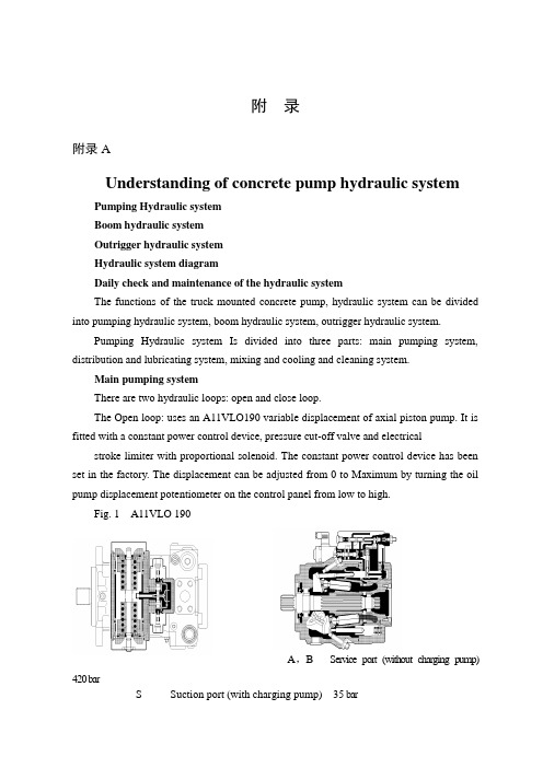
附录附录AUnderstanding of concrete pump hydraulic systemPumping Hydraulic systemBoom hydraulic systemOutrigger hydraulic systemHydraulic system diagramDaily check and maintenance of the hydraulic systemThe functions of the truck mounted concrete pump, hydraulic system can be divided into pumping hydraulic system, boom hydraulic system, outrigger hydraulic system.Pumping Hydraulic system Is divided into three parts: main pumping system, distribution and lubricating system, mixing and cooling and cleaning system.Main pumping systemThere are two hydraulic loops: open and close loop.The Open loop: uses an A11VLO190 variable displacement of axial piston pump. It is fitted with a constant power control device, pressure cut-off valve and electrical stroke limiter with proportional solenoid. The constant power control device has beenset in the factory. The displacement can be adjusted from 0 to Maximum by turning the oil pump displacement potentiometer on the control panel from low to high.Fig. 1 A11VLO 190A,B Service port (without charging pump) 420 barS Suction port (with charging pump) 35 barT1, T2 Air bleed, tankR Air bleed, oil drainM1 Measuring point, regulating chamberM Measuring point, service portG Port for positioning pressure (controller) for version with stroke limiter (H.., U2), HD and EP with screwed fitting GE10 – PLM (otherwise port G closed)The other is the control line, which can change the flow direction and the displacement of main pump through constant power valve, proportional solenoid pressure reducing valve, directional control valve and servo valve of main pump.The Closed loop: There is an auxiliary pump with relief valve that the setting pressure is 3.5Mpa in A4VG180. The auxiliary pump has two output ways. One is the charge oil line, which connects with suction line of main pump through the check valve in two pressure relief valves and add oil to main pump. At the same time excessive hydraulic oil return to oil tank through flushing valve and cooler to realize heat exchange for closed loop.A, B Service line ports SAE 1 1/4", high pressure series 420 barT1 Case drain or filling portT2 Case drain M33×2; 18 deepM A, M B Pressure gauge - operating pressure A, BR Air bleedS Boost suction portX1, X2Control pressure ports (before the orifice)G Pressure port for auxiliary circuitP S Control pressure supplyFa Filter outletFa1Filter outlet (filter assembly)Fe Filter inlet M33×2; 18 deepF S Port from filter to suction line (cold start)M H Port for balanced high pressureY1, Y2Remote control ports (only for HD control)Flushing valveUsed for closed loop to prevent excessive heat build-up in closed circuit operation. The setting pressure of flushing valve is 3.0MPaPressure reducing valve with proportional solenoidUsed for closed loop. The Output pressure is connected with the remote control port of main pump to control the displacement and is controlled by a proportional current signal and constant power valve. The displacement can be adjusted from 0 to Maximum by turning the displacement adjusting potentiometer.Constant power valveUsed for closed loop. When the hydraulic system pressure is over the setting pressure, the valve works to reduce the output pressure of the pressure reducing valve and maintain the constant power.Fig.3 Constant power valveMain pump suction filterOpen loop: filtration fineness 100u.Close loop: filtration fineness 20u.When the indicator in the vacuum gauge exceeds the safe area or the electric signal instrument gives a warning, the cartridge may be blocked. It should be clean or replace filter cartridge promptly.Filter filtration fineness is 20u in open loop. When the reading pressure of the vacuum gauge exceeds 0.35Mpa, the cartridge may be blocked. It should be clean or Return filterreplace filter cartridge promptly.Filter filtration fineness is 10u in closed loop. When the electricity deliver reports to the police, the cartridge may be blocked, it should be clean or replace filter cartridge promptly.Distribution and lubricating systemConstant pressure pumpFig.4 Constant pressure pumpAn A10VO28 constant pump is used for the distribution system of supply oil.The setting of the pressure control valve of the pump is 16Mpa. Once the system pressure is reached, the bump will keep this pressure then decrease the displacement. Thereis a pressure relief valve in the distribution circuit to act as a safety valve, which is set to 18Mpa.Plate ball valve (shut-off valve)Used to discharge the accumulator. It must be rotated the lever of shut-off valve anti-clockwise when the pumping finishes or stopped for maintenance, in order to discharge the pressure of theaccumulator. (Pressure gauge of distribution system is zero) AccumulatorInflation pressure is 8-9Mpa. Use Only Nitrogen to fill the accumulator. Charging pressure should not exceed these figures.Lubricating systemThere are two types. One is reciprocating centralized lubrication that is driven by oil from the swing cylinders of distribution system includes lubricating single pump (or double pump), distributor, damper and filter. The other is automatic centralized lubrication that is driven by a D.C motor with an independent grease tank and independent from the hydraulic system. The interval time of lubrication is carried out in the factory. The lubrication system works automatically when pumping.Mixing, cooling, cleaning systemOnly the Mixing, cooling, cleaning system are driven by motor in open loop.Gear pumpGear pump supplies oil to the mixing, cooling, cleaning system.Sandwich type relief valveThe pressure is set to 14Mpa.Ressure relayIf the mixing blade is stuck, the system pressure will raise. When the pressure exceeds the setting value (usually 10Mpa), the pressure relay will give a warning. The Solenoid directional control valve changes direction to let the mixing motor to rotate anti-clockwise. After 6 second the solenoid valve will reset, and the mixing motor will rotate clockwise again.Return filterThe filtration fineness is 10u in closed loop. The cartridge may be blocked when the electric alarm sounds. It should be replace promptly.Boom hydraulic systemBoom pumpBoom and outrigger use the same pump.37m and 40m truck mounted concrete pumps: A2FO23 fixed displacement pump44m and 47m truck mounted concrete pumps: A7VO55LRDS variable displacement pump, or A7VO55DRS variable displacement pump46m and 49m truck mounted concrete pumps: A7VO55LRDS variable displacement pumpFig.5 A7VO55DRS Fig.6 A7VO55LRDS Fig.7 A2FO23Boom proportional directional spool valveThe proportional directional spool valve with electro-hydraulic consists of pressure relief valve, pressure reducing valve, and flow control valve, and can becontrolled manual or by remote control.Fig.8 Boom proportional directional spool valveLoad-holding valveLoad-holding valve has thre e functions. (1) It acts as a lock when the cylinder isn’t moving. (2) Load-holding valve has twice relief function to protect boom against vibrating. It will be adjusted in the factory. (3) When the boom moves downward asSlewing load-holding valvegravity load, it can limit speed to prevent the boom falling too quickly and shaking.There are three main functions. Lock, overload protection and speed limiting.Outrigger hydraulic systemOutrigger hydraulic system and boom hydraulic system are used the same pump to supply oil. Outriggers should be set up before the boom is operated by the control levers or electric control button on both sides of the truck mounted concrete pump.Outrigger proportional directional spool valveIt is an integrated unit with a relief valve inside to control maximum pressure of theoutrigger hydraulic system.Fig .9 Outrigger proportional directional spool valveOutrigger hydraulic lockIt is used to lock the outrigger cylinders and pay attention to the vertical moving of the outrigger cylinder when working .Pressurerelief附录B混凝土泵车液压系统的认识泵送单元液压系统 臂架液压系统 支腿液压系统 液压原理图液压系统的日常保养及维护泵车液压系统按泵车功能可划分为泵送单元液压系统、臂架液压系统、支腿液压系统。
液压机械与液压泵外文翻译文献

液压机械与液压泵外文翻译文献液压机械与液压泵外文翻译文献(文档含中英文对照即英文原文和中文翻译)Hydraulic machinery and pumpHydraulic machinery are machines and tools which use fluid power to do work. Heavy equipment is a common example.In this type of machine, high-pressure liquid - called hydraulic fluid - is transmitted throughout the machine to various hydraulic motors and hydraulic cylinders. The fluid is controlled directly or automatically by control valves and distributed through hoses and tubes.The popularity of hydraulic machinery is due to the very large amount ofpower that can be transferred through small tubes and flexible hoses, and the high power density and wide array of actuators that can make use of this power.Hydraulic machinery is operated by the use of hydraulics, where a liquid is the powering medium. Pneumatics, on the other side, is based on the use of a gas as the medium for power transmission, generation and control.Hydraulic circuitsFor the hydraulic fluid to do work, it must flow to the actuator and or motors, then return to a reservoir.The fluid is then filtered and re-pumped. The path taken by hydraulic fluid is called a hydraulic circuit of which there are several types. Open center circuits use pumps which supply a continuous flow. The flow is returned to tank through the control valve's open center; that is, when the control valve is centered, it provides an open return path to tank and the fluid is not pumped to a high pressure. Otherwise, if the control valve is actuated it routes fluid to and from an actuator and tank. The fluid's pressure will rise to meet any resistance, since the pump has a constant output. If the pressure rises too high, fluid returns to tank through a pressure relief valve.Hydraulic pumps supply fluid to the components in the system. Pressure in the system develops in reaction to the load. Hence,a pump rated for 5,000 psi is capable of maintaining flow against a load of 5,000 psi.Pumps have a power density about ten times greater than an electric motor (by volume). They are powered by an electric motor or an engine, connected through gears, belts, or a flexible elastomeric coupling to reduce vibration.Common types of hydraulic pumps to hydraulic machinery applications are;Gear pump: cheap, durable, simple. Less efficient, because they are constant displacement, and mainly suitable for pressures below 20 MPa (3000 psi).Vane pump: cheap and simple, reliable (especially in g-rotor form). Good for higher-flow low-pressure output.Axial piston pump: many designed with a variable displacement mechanism, to vary output flow for automatic control of pressure. There are various axial piston pump designs, including swashplate and checkball. The most common is the swashplate pump.Radial piston pump: A pump that is normally used for very high pressure at small flows.Piston pumps are more expensive than gear or vane pumps, but provide longer life operating at higher pressure, with difficult fluids and longer continuous duty cycles. Pistonpumps make up one half of a hydrostatic transmission. Control valvesDirectional control valves route the fluid to the desired actuator. They usually consist of a spool inside a cast iron or steel housing.Directional control valves are usually designed to be stackable, with one valve for each hydraulic cylinder, and one fluid input supplying all the valves in the stack.The spool position may be actuated by mechanical levers, hydraulic pilot pressure, or solenoids which push the spool left or right.The main valve block is usually a stack of off the shelf directional control valves chosen by flow capacity and performance. Some valves are designed to be proportional (flow rate proportional to valve position), while others may be simply on-off. The control valve is one of the most expensive and sensitive parts of a hydraulic circuit.Pressure relief valves are used in several places in hydraulic machinery; on the return circuit to maintain a small amount of pressure for brakes, pilot lines, etc... On hydraulic cylinders, to prevent overloading and hydraulic line rupture. On the hydraulic reservoir, to maintain a small positive pressurewhich excludes moisture and contamination.Pressure reducing valves reduce the supply pressure as needed for various circuits.Check valves are one-way valves, allowing an accumulator to charge and maintain its pressure after the machine is turned off, for example.Counterbalance valves are in fact a special type of pilot controlled check valve. Whereas the check valve is open or closed, the counterbalance valve acts a bit like a pilot controlled flow control.Hydraulic pump typesGear pumpsGear pumps (with external teeth) (fixed displacement) are simple and economical pumps. The swept volume or displacement of gear pumps for hydraulics will be between about 1 cm3(0.001 litre) and 200 cm3(0.2 litre). These pumps create pressure through the meshing of the gear teeth, which forces fluid around the gears to pressurize the outlet side. Some gear pumps can be quite noisy, compared to other types, but modern gear pumps are highly reliable and much quieter than older models.Rotary vane pumpsRotary vane pumps (fixed and simple adjustable displacement) have higher efficiencies than gear pumps, but are also used for mid pressures up to 180 bars in general. Some types of vane pumps can change the centre of the vane body, so that a simple adjustable pump is obtained. These adjustable vane pumps are in general constant pressure or constant power pumps: the displacement is increased until the required pressure or power is reached and subsequently the displacement or swept volume is decreased until an equilibrium is reached.Screw pumpsScrew pumps (fixed displacement) are a double Archimedes' screw, but closed. This means that two screws are used in one body. The pumps are used for high flows and relatively low pressure (max 100 bar). They were used on board ships where the constant pressure hydraulic system was going through the whole ship, especially for the control of ball valves, but also for the steering gear and help drive systems. The advantage of the screw pumps is the low sound level of these pumps; the efficiency is not that high.Bent axis pumpsBent axis pumps, axial piston pumps and motors using the bent axis principle, fixed or adjustable displacement, exists in two different basic designs. The Thoma-principle (engineer Hans Thoma, Germany, patent 1935) with max 25 degrees angle and the Wahlmark-principle (GunnarAxel Wahlmark, patent 1960) with spherical-shaped pistons in one piece with the piston rod, piston rings, and maximum 40 degrees between the driveshaft centerline and pistons (V olvo Hydraulics Co.). These have the best efficiency of all pumps. Although in general the largest displacements are approximately one litre per revolution, if necessary a two-liter swept volume pump can be built. Often variable-displacement pumps are used, so that the oil flow can be adjusted carefully. These pumps can in general work with a working pressure of up to 350–420 bars in continuous work.Axial piston pumps swashplate principleAxial piston pumps using the swashplate principle (fixed and adjustable displacement) have a quality that is almost the same as the bent axis model. They have the advantage of being more compact in design. The pumps are easier and more economical to manufacture; the disadvantage is that they are more sensitive to oil contamination.Radial piston pumpsRadial piston pumps (fixed displacement) are used especially for high pressure and relatively small flows. Pressures of up to 650 bar are normal. In fact variable displacement is not possible, but sometimes the pump is designed in such a way that the plungers can be switched off one by one, so that a sort of variable displacement pump is obtained.Peristaltic pumpsPeristaltic pumps are not generally used for high pressures.Pumps for open and closed systemsMost pumps are working in open systems. The pump draws oil from a reservoir at atmospheric pressure. It is very important that there is no cavitation at the suction side of the pump. For this reason the connection of the suction side of the pump is larger in diameter than the connection of the pressure side. In case of the use of multi-pump assemblies, the suction connection of the pump is often combined. It is preferred to have free flow to the pump (pressure at inlet of pump at least 0.8 bars). The body of the pump is often in open connection with the suction side of the pump.In case of a closed system, both sides of the pump can be at high pressure. The reservoir is often pressurized with 6-20 bars boost pressure. For closed loop systems, normally axial piston pumps are used. Because both sides are pressurized, the body of the pump needs a separate leakage connection.Multi pump assemblyIn a hydraulic installation, one pump can serve more cylinders and motors. The problem however is that in that case a constant pressure system is required and the system always needs the full power. It is more economic to give each cylinder and motor its own pump. In that case multi pump assemblies can be used. Gearpumps can often be obtained as multi pumps.The different chambers (sometimes of different size) are mounted in one body or built together. Also vane pumps can often be obtained as a multi pump. Gerotor pumps are often supplied as multi pumps. Screw pumps can be built together with a gear pump or a vane pump. Axial piston swashplate pumps can be built together with a second pump of the same or smaller size, or can be built together with one or more gear pumps or vane pumps (depending on the supplier). Axial plunger pumps of the bent axis design can not be built together with other pumps.翻译:液压机械及泵液压机械是机械和工具,它使用流体的力量去做的工作。
混凝土泵液压系统设计

中文摘要我们的设计课题是混凝土泵液压系统设计。
本设计主要讲述混凝土泵的液压系统,以及混凝土泵液压元件的选择。
设计时注重系统性、实用性,又体现精简原则,注意所学知识的全方位结合。
随着建筑技术的不断发展,泵送混凝土施工技术得到普及和应用。
泵送混凝土不仅能改善混凝土的施工性能,对薄壁密筋结构少振捣或不振捣施工,具有提高抗渗性、改善耐久性特点。
关键词:混凝土泵、液压系统、分配阀、液压泵、液压缸。
AbstractOur design is the subject of concrete pump hydraulic system design. The design main give an account of pump hydraulic system and option of pump hydraulic components. Focus on the design of systematic, practical, reflect the principle of streamlining, the attention of theall-round knowledge of the combination.Key words: concrete pumps, hydraulic system, the distribution valves, hydraulic pumps, hydraulic cylinders.Along with building technology's unceasing development, the pump concrete construction technique obtains the popularization and the application. The pump concrete not can only improve the concretes the construction performance, little inspires to the thin wall dense muscle structure pounds or pounds the construction dispiritedly, has enhances the impermeability, the improvement durable characteristic.目录第一章概论 (4)第二章混凝土泵液压系统 (5)2.1泵送系统 (6)2.2摆动系统 (8)2.3搅拌系统 (9)第三章液压元件的选择 (10)3.1混凝土泵的型号选择 (10)3.2液压缸 (15)3.3电动机的选型 (18)3.4 液压阀 (22)3.4.1 (22)3.4.2 (28)3.4.3 (28)3.4.4 (28)3.4.5 (29)3.5 蓄能器的选择 (29)3.5.1 (29)3.5.2 (30)3.6 油管 (31)3.6.1 (31)3.6.2 (31)3.6.3 (31)3.7 油箱的设计 (33)3.7.1 (33)3.7.2 (33)3.7.3 (33)3.7.4 (34)结束语 (36)参考文献 (36)第一章概论1.混凝土的输送与浇铸一直是人们研究的对象,也是一项关键性的工作,在不同的施工条件下,合理的选择混凝土输送方法和输送设备,对加快工程速度,降低工程造价,提高劳动生产率,保证混凝土结构的质量等都有及其重要的意义。
液压系统外文文献翻译、中英文翻译、外文文献翻译
附录Hydraulic SystemHydraulic presser drive and air pressure drive hydraulic fluid as the transmission is made according to the 17th century, Pascal's principle of hydrostatic pressure to drive the development of an emerging technology, the United Kingdom in 1795 •Barman Joseph (Joseph Barman, 1749-1814), in London water as a medium to form hydraulic press used in industry, the birth of the world's first hydraulic press. Media work in 1905 will be replaced by oil-water and further improved.After the World War I (1914-1918) ,because of the extensive application of hydraulic transmission, especially after 1920, more rapid development. Hydraulic components in the late 19th century about the early 20th century, 20 years, only started to enter the formal phase of industrial production. 1925 Vickers (F. Vickers) the invention of the pressure balanced vane pump, hydraulic components for the modern industrial or hydraulic transmission of the gradual establishment of the foundation. The early 20th century G • Constantia scofluctuations of the energy carried out by passing theoretical and practical research; in 1910 on the hydraulic trans- mission (hydraulic coupling, hydraulic torque converter, etc.) contributions, so that these two areas of development.The Second World War (1941-1945) period, in the United States 30% of machine tool applications in the hydraulic transmission. It should be noted that the development of hydraulic transmission in Japan than Europe and the United States and other countries fornearly 20 years later. Before and after in 1955, the rapid development of Japan's hydraulic drive, set up in 1956, "Hydraulic Industry." Nearly 20 to 30 years, the development of Japan's fast hydraulic transmission, a world leader.Hydraulic transmission There are many outstanding advantages, it is widely used, such as general industrial use of plastics processing machinery, the pressure of machinery, machine tools, etc.; operating machinery engineering machinery, construction machinery, agricultural machinery, automobiles, etc.; iron and steel industry metallurgical machinery, lifting equipment, such as roller adjustment device; civil water projects with flood control and dam gate devices, bed lifts installations, bridges and other manipulation of institutions; speed turbine power plant installations, nuclear power plants, etc.; ship from the deck heavy machinery (winch), the bow doors, bulkhead valve, stern thruster, etc.; special antenna technology giant with control devices, measurement buoys, movements such as rotating stage; military-industrial control devices used in artillery, ship anti- rolling devices, aircraft simulation, aircraft retractable landing gear and rudder control devices and other devices.A complete hydraulic system consists of five parts, namely, power components, the implementation of components, control components, auxiliary components and hydraulic oil.The role of dynamic components of the original motive fluid into mechanical energy to the pressure that the hydraulic system of pumps, it is to power the entire hydraulic system. The structure of the form of hydra- ulic pump gears are generally pump, vane pump and piston pump.Implementation of components (such as hydraulic cylinders and hydraulic motors) which isthe pressure of the liquid can be converted to mechanical energy to drive the load for a straight line reciprocating movement or rotational movement.Control components (that is, the various hydraulic valves) in the hydraulic system to control and regulate the pressure of liquid, flow rate and direction. According to the different control functions, hydraulic pressure control valve can be divided into valves, flow control valves and directional control valve. Pressure control valves are divided into benefits flow valve (safety valve), pressure relief valve, sequence valve, pressure relays, etc.; flow control valves including throttle, adjusting the valves, flow diversion valve sets, etc.; directional control valve includes a one-way valve , one-way fluid control valve, shuttle valve, valve and so on. Under the control of different ways, can be divided into the hydraulic valve control switch valve, control valve and set the value of the ratio control valve.Auxiliary components, including fuel tanks, oil filters, tubing and pipe joints, seals, pressure gauge, oil level, such as oil dollars.Hydraulic oil in the hydraulic system is the work of the energy transfer medium, there are a variety of mineral oil, emulsion oil hydraulic molding Hop categories.The role of the hydraulic system is to help humanity work. Mainly by the implementation of components to rotate or pressure into a reciprocating motion.Hydraulic system and hydraulic power control signal is composed of two parts, the signal control of some parts of the hydraulic power used to drive the control valve movement.Part of the hydraulic power means that the circuit diagram used to show the differentfunctions of the interrelationship between components. Containing the source of hydraulic pump, hydraulic motor and auxiliary components; hydraulic control part contains a variety of control valves, used to control the flow of oil, pressure and direction; operative or hydraulic cylinder with hydraulic motors, according to the actual requirements of their choice.In the analysis and design of the actual task, the general block diagram shows the actual operation of equipment. Hollow arrow indicates the signal flow, while the solid arrows that energy flow.Basic hydraulic circuit of the action sequence - Control components (two four-way valve) and the spring to reset for the implementation of components (double-acting hydraulic cylinder), as well as the extending and retracting the relief valve opened and closed. For the implementation of components and control components, presentations are based on the corresponding circuit diagram symbols, it also introduced ready made circuit diagram symbols.Working principle of the system, you can turn on all circuits to code. If the first implementation of components numbered 0, the control components associated with the identifier is 1. Out with the implementation of components corresponding to the identifier for the even components, then retracting and implementation of components corresponding to the identifier for the odd components. Hydraulic circuit carried out not only to deal with numbers, but also to deal with the actual device ID, in order to detect system failures.DIN ISO1219-2 standard definition of the number of component composition, which includes the following four parts: device ID, circuit ID, component ID and component ID.The entire system if only one device, device number may be omitted.Practice, another way is to code all of the hydraulic system components for numbers at this time, components and component code should be consistent with the list of numbers. This method is particularly applicable to complex hydraulic control system, each control loop are the corresponding number with the systemWith mechanical transmission, electrical transmission compared to the hydraulic drive has the following advantages:1. a variety of hydraulic components can easily and flexibly to layout.2. light weight, small size, small inertia, fast response.3. to facilitate manipulation of control, enabling a wide range of stepless speed regulation (speed range of 2000:1).4. to achieve overload protection automatically.5. the general use of mineral oil as a working medium, the relative motion can be self-lubricating surface, long service life;6. it is easy to achieve linear motion .7. it is easy to achieve the automation of machines, when the joint control of the use of electro-hydraulic, not only can achieve a higher degree of process automation, and remote control can be achieved.The shortcomings of the hydraulic system:1. as a result of the resistance to fluid flow and leakage of the larger, so less efficient. If not handled properly, leakage is not only contaminated sites, but also may cause fire and explosion.2. vulnerable performance as a result of the impact of temperature change, it would be inappropriate in the high or low temperature conditions.3. the manufacture of precision hydraulic components require a higher, more expensive and hence the price.4. due to the leakage of liquid medium and the compressibility and can not be strictly the transmission ratio.5. hydraulic transmission is not easy to find out the reasons for failure; the use and maintenance requirements for a higher level of technology.In the hydraulic system and its system, the sealing device to prevent leakage of the work of media within and outside the dust and the intrusion of foreign bodies. Seals played the role of components, namely seals. Medium will result in leakage of waste, pollution and environmental machinery and even give rise to malfunctioning machinery and equipment for personal accident. Leakage within the hydraulic system will cause a sharp drop in volumetric efficiency, amounting to less than the required pressure, can not even work. Micro-invasive system of dust particles, can cause or exacerbate friction hydraulic component wear, and further lead to leakage.Therefore, seals and sealing device is an important hydraulic equipment components. The reliability of its work and life, is a measure of the hydraulic system an important indicator of good or bad. In addition to the closed space, are the use of seals, so that two adjacent coupling surface of the gap between the need to control the liquid can be sealed following the smallest gap. In the contact seal, pressed into self-seal-style and self-styled self-tight seal (ie, sealed lips) two.The three hydraulic system diseases1. as a result of heat transmission medium (hydraulic oil) in the flow velocity in various parts of the existence of different, resulting in the existence of a liquid within the internal friction of liquids and pipelines at the same time there is friction between the inner wall, which are a result of hydraulic the reasons for the oil temperature. Temperature will lead to increased internal and external leakage, reducing its mechanical efficiency. At the same time as a result of high temperature, hydraulic oil expansion will occur, resulting in increased com- pression, so that action can not be very good control of transmission. Solution: heat is the inherent characteristics of the hydraulic system, not only to minimize eradication. Use a good quality hydraulic oil, hydraulic piping arrangement should be avoided as far as possible the emergence of bend, the use of high-quality pipe and fittings, hydraulic valves, etc.2. the vibration of the vibration of the hydraulic system is also one of its malaise. As a result of hydraulic oil in the pipeline flow of high-speed impact and the control valve to open the closure of the impact of the process are the reasons for the vibration system. Strong vibration control action will cause the system to error, the system will also be some of the more sophisticated equipment error, resulting in system failures. Solutions: hydraulic pipe should be fixed to avoid sharp bends. To avoid frequent changes in flow direction, can not avoid damping measures should be doing a good job. The entire hydraulic system should have a good damping measures, while avoiding the external local oscillator on the system.3. the leakage of the hydraulic system leak into inside and outside the leakage. Leakagerefers to the process with the leak occurred in the system, such as hydraulic piston-cylinder on both sides of the leakage, the control valve spool and valve body, such as between the leakage. Although no internal leakage of hydra- ulic fluid loss, but due to leakage, the control of the established movements may be affected until the cause system failures. Outside means the occurrence of leakage in the system and the leakage between the external environment. Direct leakage of hydraulic oil into the environment, in addition to the system will affect the working environment, not enough pressure will cause the system to trigger a fault. Leakage into the environment of the hydraulic oil was also the danger of fire. Solution: the use of better quality seals to improve the machining accuracy of equipment.Another: the hydraulic system for the three diseases, it was summed up: "fever, with a father拉稀" (This is the summary of the northeast people). Hydraulic system for the lifts, excavators, pumping station, dynamic, crane, and so on large-scale industry, construction, factories, enterprises, as well as elevators, lifting platforms, Deng Axle industry and so on.Hydraulic components will be high-performance, high-quality, high reliability, the system sets the direction of development; to the low power, low noise, vibration, without leakage, as well as pollution control, water-based media applications to adapt to environmental requirements, such as the direction of development; the development of highly integrated high power density, intelligence, macaronis and micro-light mini-hydraulic components; active use of new techniques, new materials and electronics, sensing and other high-tech.---- Hydraulic coupling to high-speed high-power and integrated development of hydraulic transmission equipment, development of water hydraulic coupling medium speedand the field of automotive applications to develop hydraulic reducer, improve product reliability and working hours MTBF; hydraulic torque converter to the development of high-power products, parts and components to improve the manufacturing process technology to improve reliability, promote computer-aided technology, the development of hydraulic torque converter and power shift transmission technology supporting the use of ; Clutch fluid viscosity should increase the quality of products, the formation of bulk to the high-power and high-speed direction.Pneumatic Industry:---- Products to small size, light weight, low power consumption, integrated portfolio of development, the implementation of the various types of components, compact structure, high positioning accuracy of the direction of development; pneumatic components and electronic technology, to the intelligent direction of development; component performance to high-speed, high-frequency, high-response, high-life, high temp- erature, high voltage direction, commonly used oil-free lubrication, application of new technology, new technology and new materials.1. Used high-pressure hydraulic components and the pressure of continuous work to reach 40Mpa, the maximum pressure to achieve instant 48Mpa;2. Diversification of regulation and control;3. To further improve the regulation performance, increase the efficiency of the power train;4. Development and mechanical, hydraulic, power transmission of the composite portfolio adjustment gear;5. Development of energy saving, energy efficient system function;6. To further reduce the noise;7. Application of Hydraulic Cartridge Valves thread technology, compact structure, to reduce the oil spill.液压系统液压传动和气压传动称为流体传动,是根据17世纪帕斯卡提出的液体静压力传动原理而发展起来的一门新兴技术,1795年英国约瑟夫•布拉曼(Joseph Braman,1749-1814),在伦敦用水作为工作介质,以水压机的形式将其应用于工业上,诞生了世界上第一台水压机。
中英文文献翻译-液压制动系统
附录AHydraulic Brake SystemsWhen you step on the brake pedal,you expect the vehicle to stop.The brake pedal operates a hydraulic that is used for two reasons.First,fluid under pressure can be carried to all parts of the vehicle by small hoses or metal lines without taking up a lot of room of causing routing problems.Second,the hydraulic fluid offers a great mechanical advantage-little foot pressure is required on the pedal,but a great deal of pressure is generated at the wheels.The brake pedal is linked to a piston in the brake master cylinder containing a small piston and a fluid reservoir.Modern master cylinders are actually two separate cylinders.Such a system is called a dual circuit,because the front cylinder is connected to the front brakes and the rear cylinder to the rear brakes.(Some vehicles are connected diagonally).The two cylinders are actually separated,allowing for emergency stopping power should one part of the system fail.The entire hydraulic system from the master cylinder to the wheels is full of hydraulic brake fluid.When the brake pedal is depressed,the piston in the master cylinder are forced to move,exerting tremendous force on the fluid in the lines.The fluid has nowhere to go,and forces the wheel cylinder pistons(drum brakes) orcaliper pistons(disc brakes) to exert pressure on the brake shoes or pads.The friction between the brake shoe and wheel drum or the brake pad and rotor (disc) slows the vehiche and eventually stops it.Also attached to the brake pedal si a switch that lights the brake lights as the pedal is depressed.The lights stay on until the brake pedal is released and returns to its normal position.Each wheel cylinder in a drum brake system contains two pistons,one at either end,which push outward in opposite directions.In disc brake systems,the wheel cylinders are part of the caliper (there can be as many as four or as few as one ).Whether disc or drum type,all pistons use some type of rubber seal to prevent leakage around thepiston,and a rubber dust boot seals the outer of the wheel cylinders against dirt and moisture.When the brake pedal is released,a spring pushes the master cylinder pistons back to their normal positions.Check valves in the master cylinder piston allow fluid to flow toward the wheel cylinders or calipers as the piston returns.Then as the brake shoe return springs pull the brake shoes back to the released position,excess fluid returns to the master cylinder through compensating ports,which have been uncovered as the pistons move back.Any fluid that has leaked from the system will also be replaced through the compensating ports.All dual circuit brake systems use a switch to activate a light,warning of brake failure.The switch si located in a valve mounted near the master cylinder.A piston in the valve reveives pressure on each end from the front and rear brake circuits.When the pressures are balanced,the piston remains stationary,but when one circuit has a leak,greater pressure during the application of the brakes will force the piston to one side or the other,closing the switch and activating the warning light.The light can also be activated by the ignition switch during engine starting or by the parking brake.Front disc,rear drum brake systems also have a metering valve to prevent the front disc brakes from engaging before the rear brakes have contacted the drums.This ensures that the front brakes will not normally be used alone to stop the vehicle.A proportioning valve is also used to limit pressure to the rear brakes to prevent rear wheel lock-up during hard braking.Brake shoes and pads are constructed in a similar.The pad or shoe is composed of a metal backing plate and a priction lining.The lining is either bonded(glued) to the metal,or riveted.Generally,riveted linings provide superior performance,but good quality bonded linings are perfectly adequate.Friction materials will vary between manufacturers and type of pad and the material compound may be referred to as asbestos,organic,semi-metallic,metallic.The difference between these compounds lies in the types and percentages of friction materials used,material binders and performance modifiers.Generally speaking,organic and non-metallic asbestos compound brakes are quiet,easy on rotors and provide good feel.But this comes at the expense of high temperature operation,so they may not be your best choice for heavy duty use or mountiandriving.In most cases,these linings will wear somewhat faster than metallic compound pads,so you will usually replace them more often.But,when using these pads,rotors tend to last longer.Semi-metallic or metallic compound brake linings will vary in performance based on the metallic contents of the compound.Again,generally speaking,the higher the metallic content,the better the friction material will resist heat.This makes them more appropriate for heavy duty applications,but at the expense of braking performance before the pad reaches operating temperature.The first few applications on a cold morning may not give strong braking.Also,metallics and semi-metallics are more likely to squeal,In most cases,metallic compounds last longer than non-metallic pads,but they tend to cause more wear on the rotors.If you use metallic pads,expect to replace the rotors more often.When deciding what type of brake lining is right for you,keep in mind that today’s modern cars have brake materials which are matched to the expected vehicle’s performance capabilities.Changing the material from OEM specification could adversely addect brake feel or responsiveness.Before changing the brake materials,talk to your deaker or parts supplier to help decide what is most appropriate for your application. Remenber that use applications such as towing,stop and go driving,driving down mountain roads,and racing may require a change to a higher performance material.Some more exotic materials are also used in brake linings,among which are Kevlar and carbon compounds.These materials have the capability of extremely good performance for towing,mountain driving or racing.Wear characteristics can be similar to either applications tend to wear like metallic linings,while many of the streetapplications aremore like the non-metallics.附录B液压制动系统当踩下制动踏板,您希望该车辆停下。
液压系统-文献翻译
Hydraulic SystemThere are only three basic methods of transmitting power: electrical, mechanical, and fluid power. Most applications actually use a combination of the three methods to obtain the most efficient overall system. To properly determine which principle method to use, it is important to know the salient features of each type. For example, fluid systems can transmit power more economically over greater distances than can mechanical types. However, fluid systems are restricted to shorter distances than are electrical systems.Hydraulic power transmission system are concerned with the generation, modulation, and control of pressure and flow, and in general such systems include:1.Pumps which convert available power from the prime mover to hydraulic power at the actuator.2.Valves which control the direction of pump-flow, the level of power produced, and the amount of fluid-flow to the actuators. The power level is determined by controlling both the flow and pressure level.3.Actuators which convert hydraulic power to usable mechanical power output at the point required.4.The medium, which is a liquid, provides rigid transmission and control as well as lubrication of components, sealing in valves, and cooling of the system.5.Connectors which link the various system components, provide power conductors for the fluid under pressure, and fluid flow return to tank (reservoir).6.Fluid storage and conditioning equipment which ensure sufficient quality and quantity as well as cooling of the fluid.Hydraulic systems are used in industrial applications such as stamping presses, steel mills , and general manufacturing , agricultural machines , mining industry , aviation , space technology , deep-sea exploration ,transportation , marinetechnology , and offshore gas petroleum exploration . In short, very few people get through a day of their lives without somehow benefiting from the technology of hydraulics.The secret of hydraulic system’s success and widespread use is its versatility and manageability. Fluid power is not hindered by the geometry of the machine as is the case in mechanical systems. Also, power can be transmitted in almost limitless quantities because fluid systems are not so limited by the physical limitations of materials as are the electrical systems. For example, the performance of an electromagnet is limited by the saturation limit of steel. On the other hand, the power limit of fluid systems is limited only by the strength capacity of the material.Industry is going to depend more and more on automation in order to increase productivity. This includes remote and direct control of production operations, manufacturing processes, and materials handling. Fluid power is the muscle of automation because of advantages in the following four major categories.Ease and accuracy of control. By the use of simple levers and push buttons, the operator of a fluid power systems can readily start, stop, speed up or slow down, and position force which provide any desired horsepower with tolerances as precise as one ten-thousandth of an inch.Multiplication of force. A fluid power system (without using cumbersome gears, pulleys, and levers) can multiply forces simply and efficiently from a fraction of an ounce to several hundred tons of output.Constant force or torque. Only fluid power systems are capable of providing constant force or torque regardless of speed changes. This is accomplished whether the work output moves a few inches per hour, several hundred inches per minute, a few revolutions per hour, or thousands of revolutions per minute.Simplicity, safety, economy. In general, fluid power systems use fewer movingparts than comparable mechanical or electrical systems. Thus, they are simpler to maintain and operate. This, in turn, maximizes safety, compactness, and reliability. For example, a new power steering control designed has made all other kinds of power systems obsolete on many off-highway vehicles. The steering unit consists of a manually operated directional control valve and meter in a single body. Because the sterring unit is fully fluid-linked, mechanical linkages, universal joints, bearings, reduction gears, ect . are eliminated. This provides a simple,compact systems.In addition, very little input torque is required to produce the control needed for the toughest applications. This is important where limitations of control space require a small sterring wheel and it becomes necessary to reduce operator fatigue.Additional benefits of fluid power systems include instantly reversible motion, automatic protection against overloads, and infinitely variable speed control. Fluid power systems also have the highest horsepower per weight ratio of any known power source. In spite of all these highly desirable features of fluid power, it is not a panacea for all power transmission problems. Hydraulic systems also have some drawbacks. Hydraulic oils are messy, and leakage is impossible to completely. Also, most hydraulic oils can cause fires if an oil leak occurs in area of hot equipment. There are only three basic methods of transmitting power: electrical, mechanical, and fluid power. Most applications actually use a combination of the three methods to obtain the most efficient overall system. To properly determine which principle method to use, it is important to know the salient features of each type. For example, fluid systems can transmit power more economically over greater distances than can mechanical types. However, fluid systems are restricted to shorter distances than are electrical systems.Hydraulic power transmission system are concerned with the generation, modulation, and control of pressure and flow, and in general such systems include:Pumps which convert available power from the prime mover to hydraulic power at the actuator.Valves which control the direction of pump-flow, the level of power produced, and the amount of fluid-flow to the actuators. The power level is determined by controlling both the flow and pressure level.Actuators which convert hydraulic power to usable mechanical power output at the point required.The medium, which is a liquid, provides rigid transmission and control as well as lubrication of components, sealing in valves, and cooling of the system.Connectors which link the various system components, provide power conductors for the fluid under pressure, and fluid flow return to tank (reservoir).Fluid storage and conditioning equipment which ensure sufficient quality and quantity as well as cooling of the fluid.Hydraulic systems are used in industrial applications such as stamping presses, steel mills , and general manufacturing , agricultural machines , mining industry , aviation , space technology , deep-sea exploration ,transportation , marine technology , and offshore gas petroleum exploration . In short, very few people get through a day of their lives without somehow benefiting from the technology of hydraulics.The secret of hydraulic system’s success and widespread use is its versatility and manageability. Fluid power is not hindered by the geometry of the machine as is the case in mechanical systems. Also, power can be transmitted in almost limitless quantities because fluid systems are not so limited by the physical limitations of materials as are the electrical systems. For example, the performance of an electromagnet is limited by the saturation limit of steel. On the other hand, the power limit of fluid systems is limited only by the strength capacity of the material.Industry is going to depend more and more on automation in order to increase productivity. This includes remote and direct control of production operations, manufacturing processes, and materials handling. Fluid power is the muscle of automation because of advantages in the following four major categories.1. Ease and accuracy of control. By the use of simple levers and push buttons, the operator of a fluid power systems can readily start, stop, speed up or slow down, and position force which provide any desired horsepower with tolerances as precise as one ten-thousandth of an inch.2. Multiplication of force. A fluid power system (without using cumbersome gears, pulleys, and levers) can multiply forces simply and efficiently from a fraction of an ounce to several hundred tons of output.3. Constant force or torque. Only fluid power systems are capable of providing constant force or torque regardless of speed changes. This is accomplished whether the work output moves a few inches per hour, several hundred inches per minute, a few revolutions per hour, or thousands of revolutions per minute.4. Simplicity, safety, economy. In general, fluid power systems use fewer moving parts than comparable mechanical or electrical systems. Thus, they are simpler to maintain and operate. This, in turn, maximizes safety, compactness, and reliability. For example, a new power steering control designed has made all other kinds of power systems obsolete on many off-highway vehicles. The steering unit consists of a manually operated directional control valve and meter in a single body. Because the sterring unit is fully fluid-linked, mechanical linkages, universal joints, bearings, reduction gears, ect . are eliminated. This provides a simple,compact systems.In addition, very little input torque is required to produce the control needed for the toughest applications. This is important where limitations of controlspace require a small sterring wheel and it becomes necessary to reduce operator fatigue.Additional benefits of fluid power systems include instantly reversible motion, automatic protection against overloads, and infinitely variable speed control. Fluid power systems also have the highest horsepower per weight ratio of any known power source. In spite of all these highly desirable features of fluid power, it is not a panacea for all power transmission problems. Hydraulic systems also have some drawbacks. Hydraulic oils are messy, and leakage is impossible to completely. Also, most hydraulic oils can cause fires if an oil leak occurs in area of hot equipment.液压系统仅有以下三种基本方法传递动力:电气,机械和流体。
机械外文翻译文献翻译液压系统1
外文原文:Theory of fluid propertiesWe will concentrate mainly on three fluid properties in this chapter:• The density which leads to mass and hence to hydraulic inertia effects.• The viscosity which leads to the hydraulic friction effects.• The compressi bility and thus the bulk modulus which leads to the hydraulic system stiffness. Notice that the compressibility effect can be modified by air release, cavitation phenomena and by expansion of a pipe, hose or chamber containing the hydraulic fluid.1 Density and compressibility coefficientThe density is the mass of a substance per unit volume:Density has dimensions of [M/L3] and is expressed in kilograms per cubic meter [kg/m3]. As mentioned previously the density is a function of the pressure and the temperature:This function can be approximated by the first three terms of a Taylor series:This can also be expressed as:WithAndThis equation is the linearized state equation for a liquid. Using the definition of thedensity, the two coefficients α and B can also be expressed as:B is known as the isothermal bulk modulus or for simplicity the bulk modulus and α is known as the cubical expansion coefficient. Since fluid density varies with the applied pressure, this implies that a given mass of fluid submitted to a pressure change changes its volume. This phenomenon leads to the definition of the compressibility coefficient β:where β is expressed in units Pa 1 (or m2/N). Considering the relation for a closed hydraulic circuit the mass is constant, and hence:it follows thatUsing the definition of the compressibility coefficient β we obtain:More usually we use the bulk modulus B also known as the volumetric elasticity modulus:The relation between ρ and B implies mass conservation. This relation must be RIGOROUSLY RESPECTED in the calculations. In the modeling and simulation context of fluid energy systems, disregarding the relation between ρ and B leads to abnormal evolutions of pressure in the closed circuit submitted to compression and expansion cycles. This phenomenon is strongly accentuated if aeration occurs in the circuit (when dissolved air in the fluid reappears in the form of bubbles). We shall approach this point by examining the phenomena of aeration and cavitation. The aircan also have adverse consequences on a fluid compressibility. In liquid air can be present in two forms: entrapped and dissolved.Entrapped airWhen the return pipe is not submersed in the tank the liquid jet can entrain some air bubbles in the tank. Another phenomenon that affects the quantity of air in liquid is the leakage.Figure 1: Liquid leakageFigure 2: Air is entrainedThis air stays in the liquid as cavities and can modify the fluid compressibility. In this context we talk about effective bulk modulus. Figure 3 shows the bulk modulus of a diesel fuel at 40 °C with 0, 0.01, 0.1, 1, 10% air. The plot is obtained using the system shown. The model of the diesel fuel properties is based on accurate ex-perimental measurements and are designed for use with injection system which are very fast acting. For this reason air is assumed to be entrained rather than dissolved.Figure 3Dissolved airAir can also be dissolved in a liquid. A certain amount of air molecule can be part of the liquid. In this case the dissolved air does not significantly change the fluid properties.2 Air release and cavitationAir can be dissolved or entrained in liquids and it is possible for air to change from one of these two forms to the other depending on the conditions to which the fluid is subjected.Suppose the fluid is in equilibrium with a certain percentage of dissolved gas (usually air: nitrogen and oxygen). Lowering the pressure above a critical value called the saturation pressure induces aeration. This is the process where the dissolved gas forms air bubbles in the liquid until all the dissolved gases or air are free.The exact point where all the dissolved gas has come out of solution is difficult to pin-point because it depends on the chemical composition and behavior of the gas. This is a non-symmetrical dynamic process: the growing process does not have the same dynamics as when air bubbles disappear. In consequence the total amount of bubbles created when the pressure drops may or may not be redissolved in the liquid when it rises again.If the pressure is dropped further and above another critical value called the vapor pres s ure, the fluid itself starts to vaporize. It corresponds to a liquid phase change. At some point only fluid vapor and gas exist. In liquid systems the term cavitation usually refers to the formation and collapse of cavities in the liquid even if cavities contain air or liquid vapor.To summarize with a sketch what we have introduced see above:Figure 4: Air release and cavitationThe development of a cavity is now recognized as being associated with a nucleation center such as microscopic gas particles, wear or wall asperities. When the liquid is subjected to a tensile stress, cavities do not form as a result of liquid rupture but are caused by the rapid growth of these nuclei.To understand this, think of beer (or champagne if you prefer) in a bottle, when it is closed you see no air bubbles and the liquid does not look fizzy. The pressure in the bottle is above the saturation pressure of the gas in the liquid. When you open the bottle suddenly bubbles appear and so the dissolved gas (molecules of gas held in the liquid) starts to appear as gas.In fact the liquid is gas saturated and the atmospheric pressure is less than the saturation pressure of the liquid. This phenomenon is clearly not cavitation but air release (aeration). Considering nuclei effects, bubbles form only at particular places in your glass: around the glass (due to small asperities) and round any particles present in the liquid. Theoretically, if your liquid was perfectly pure and the wall of the system perfectly regular, air release or cavitation would occur with great difficulty! The key point about cavitation is that it is a phase change: the liquid changes to vapor.A comparison can be made between cavitation and boiling. If we look at the phasediagram below:Figure 5: Cavitation and boilingBoiling is a phase change at constant pressure and variable temperature and cavitation is a phase change at constant temperature and variable pressure.In any system air release starts first and if the pressure decreases further, cavitation may occur. This means that, sometimes, people talk about cavitation when the real phenomenon is air release. Both phenomena can lead to destruction of the material or component.In both cases it is entrained gas that causes the troubles. When cavities encounter high pressure in the downstream circuit, these bubbles or cavities can be unstable and can collapse implosively. The pressure developed at collapse can be large enough to cause severe mechanical damage in the containing vessel. It is well-known that hydraulic pumps and pipework can be badly damaged by cavitaton and air release.In all classical hydraulic systems air release and cavitation must be avoided to prevent material destruction but sometimes it is required like for injection systems to prepare the spray formation.3 ViscosityViscosity is a measure of the resistance of the fluid to flow. This characteristic has both positive and negative effects on fluid power systems. A low viscosity leads to oil leaks in the dead zone formed between the mechanical parts in movement, and a high viscosity will lead to loss of pressure in hydraulic ducts.Viscosity is a characteristic of liquids and gases and is manifested in motion throughinternal damping. Viscosity results from an exchange of momentum by molecular diffusion between two layers of fluid with different velocities. In this sense, the viscosity is a fluid property and not a flow property.Figure 6: ViscosityFigure 6 shows the relation between shearing constraint and difference of flow velocity between two layers .The definition of viscosity was first given by Newton. Between two layers of distance dy, the exerted force between these two layers is given by:where U(y) is the velocity depending on the radial position y and dU/dy the velocity gradient. This proportionality expresses the notion of Newtonian fluid and allows the introduction of μ defined as the dynamic viscosity or the absolute viscosity.The dimension of μ is [ML1-T 1-] and the SI unit is kg/m/s or Pa s. The older unit is the Poise, P, which is 0.1 kg/m/s. However, this is very small and hence the milli Poise, mP, is the common unit which is 10-4 kg/m/s.The dynamic viscosity is the constant of proportionality between a stress and the intensity of shearing between two neighboring layers:However the absolute viscosity is not very often used in fundamental equations. For example the dynamics of the elementary volume between the two layers is expressedas:and thus using the shear stress calculation:In other formulas (e.g. Navier Stokes) the ratio between the absolute viscosity and the density occurs so often that a new parameter called the kinematic viscosity ν is introduced .of dimension [L2T 1-] and so the SI unit is the m2/s. The older unit of kinematic viscosity is the Stoke, St, which is 104-m2/s. However, even this is a very small unit and hence the centistoke cSt is the common unit with 1 cSt = 106-m2/s. This parameter is easily measured with viscometers.Note that the viscosity varies significantly with the fluid temperature.Figure 7: Viscosity against temperatureNormally in absence of air release and cavitation the variation with pressure is not great unless the pressure is very extreme.Figure 8: Variation with pressureViscosity influence on the flowAnother important aspect of the viscosity is its influence on the flow conditions of the fluid. We can distinguish two types of flow conditions:• Laminar flow for which the flow lines are parallel and shearing forces create a pressure drop.• Turbulent flow for which the fluid particles have a disordered, random movement leading to a loss of pressure.These two conditions can be distinguished using the Reynolds number which is defined as follows:WithU: average fluid velocityd: diameter of the duct (hydraulic diameter for others geometries)ρ: densityμ: dynamic viscosityν: kinematic viscosityThe transition between laminar to turbulent flow occurs at the critical Reynolds number. This is not well defined, there exists always a transition region. In a hydraulic line, the critical Reynolds number is generally between 1500 to 2000. For uneven geometries (thin-walled orifices), the critical Reynolds number can be lower than 100. For non-circular cross sections, the hydraulic diameter can be used to determine the Reynolds number. Hydraulic diameter is defined as follows:We now give one example:• Circular orifice of diameter:Flow through orificesOrifices (also called restrictions) can be fixed or variable and occur in huge numbers in fluid systems. Not surprisingly in Engineering courses a mathematical description is presented. This is usually based on Bernoulli’s equation and leads to the formwhere Cq is the flow coefficient. This is variously described as typically 0.7 or varying with orifice geometry and Reynolds number.The second alternative is obviously more correct. If we do take a constant value, we are forced to have the gradient of Q against infinity at the origin! This cannot be and if you try to implement it is a numerical disaster! Clearly the flow is laminar for sufficiently small pressure drops which means that Cq is certainly not constant. One solution is to perform detailed e xperiments and compute Cq against Reynold’s number. In the context of the orifice (not necessarily circular) the Reynold’s number iswhere U is a mean velocity and dh the hydraulic diameter. If we take U=Q/A, we end up with the form Cq =f(Q) and ultimately withIt is possible to work with an implicit relationship like this but we would prefer an explicit formula.This is provided by introducing another dimensionless number known as the flow number and denoted by λ. This is defined asFrom a modelin g point of view λ contains quantities we know. Using λ we haveand provided we have,we have an explicit relationship which is easy to evaluate. There are no more problems to obtain measurements forthan forand so the flow number form has many advantages.References :[1] McCloy D, Discharge Characteristics of Servo Valve Orifices, 1968 Fluid International Conference.[2] R.C. Binder, “Fluid Mechanics”. 3rd Edition, 3rd Printing. Prentice-Hall, Inc., Englewood Cliffs,NJ. 1956.译文:液压油理论我们将在本章主要讨论液压油的三个特性:•密度(使油液具有质量和液感效应);•粘性(使油液具有液阻效应);•可压缩性和体积弹性模量(使油液具有容性效应),值得提醒的是容性效应会受油液中析出的空气、气穴现象和装有油液的的管道、软管或油腔的影响。
- 1、下载文档前请自行甄别文档内容的完整性,平台不提供额外的编辑、内容补充、找答案等附加服务。
- 2、"仅部分预览"的文档,不可在线预览部分如存在完整性等问题,可反馈申请退款(可完整预览的文档不适用该条件!)。
- 3、如文档侵犯您的权益,请联系客服反馈,我们会尽快为您处理(人工客服工作时间:9:00-18:30)。
译文原文:Understanding of concrete pump hydraulic systemItalian CIFA Concrete Machinery Company(1.CIFA concrete mechanical pump Institute, Italy)Pumping Hydraulic systemBoom hydraulic systemOutrigger hydraulic systemHydraulic system diagramDaily check and maintenance of the hydraulic systemThe functions of the truck mounted concrete pump, hydraulic system can be divided into pumping hydraulic system, boom hydraulic system, outrigger hydraulic system.Pumping Hydraulic system Is divided into three parts: main pumping system, distribution and lubricating system, mixing and cooling and cleaning system.Main pumping systemThere are two hydraulic loops: open and close loop.The Open loop: uses an A11VLO190 variable displacement of axial piston pump. It is fitted with a constant power control device, pressure cut-off valve and electricalstroke limiter with proportional solenoid. The constant power control device has been set in the factory. The displacement can be adjusted from 0 to Maximum by turning the oil pump displacement potentiometer on the control panel from low to high.Fig. 1 A11VLO 190A,B Service port (without charging pump) 420 barS Suction port (with charging pump) 35 barT1, T2 Air bleed, tankR Air bleed, oil drainM1 Measuring point, regulating chamberM Measuring point, service portG Port for positioning pressure (controller) for version with stroke limiter (H.., U2), HD and EP with screw ed fitting GE10 – PLM (otherwise port G closed)The other is the control line, which can change the flow direction and the displacement of main pump through constant power valve, proportional solenoid pressure reducing valve, directional control valve and servo valve of main pump.The Closed loop: There is an auxiliary pump with relief valve that the setting pressure is 3.5Mpa in A4VG180. The auxiliary pump has two output ways. One is the charge oil line, which connects with suction line of main pump through the check valve in two pressure relief valves and add oil to main pump. At the same time excessive hydraulic oil return to oil tank through flushing valve and cooler to realize heat exchange for closed loop.A, B Service line ports SAE 1 1/4", high pressure series 420 barT1 Case drain or filling portT2 Case drain M33×2; 18 deepM A, M B Pressure gauge - operating pressure A, BR Air bleedS Boost suction portX1, X2Control pressure ports (before the orifice)G Pressure port for auxiliary circuitP S Control pressure supplyFa Filter outletFa1Filter outlet (filter assembly)Fe Filter inlet M33×2; 18 deepF S Port from filter to suction line (cold start)M H Port for balanced high pressureY1, Y2Remote control ports (only for HD control)Flushing valveUsed for closed loop to prevent excessive heat build-up in closed circuit operation. The setting pressure of flushing valve is 3.0MPaPressure reducing valve with proportional solenoidUsed for closed loop. The Output pressure is connected with the remote control port of main pump to control the displacement and is controlled by a proportional current signal and constant power valve. The displacement can be adjusted from 0 to Maximum by turning the displacement adjusting potentiometer.Constant power valveUsed for closed loop. When the hydraulic system pressure is over the setting pressure, the valve works to reduce the output pressure of the pressure reducing valve and maintain the constant power.Pilot pressure setting Power settingFig.3 Constant power valveMain pump suction filterOpen loop: filtration fineness 100u.Close loop: filtration fineness 20u.When the indicator in the vacuum gauge exceeds the safe area or the electric signal instrument gives a warning, the cartridge may be blocked. It should be clean or replace filter cartridge promptly.Filter filtration fineness is 20u in open loop. When the reading pressure of the vacuum gauge exceeds 0.35Mpa, the cartridge may be blocked. It should be clean orReturn filterreplace filter cartridge promptly.Filter filtration fineness is 10u in closed loop. When the electricity deliver reports to the police, the cartridge may be blocked, it should be clean or replace filter cartridge promptly. Distribution and lubricating systemConstant pressure pumpSetting screw for pressurecontrol zero /Stroke pressureFig.4 Constant pressure pumpAn A10VO28 constant pump is used for the distribution system of supply oil.The setting of the pressure control valve of the pump is 16Mpa. Once the system pressure is reached,the bump will keep this pressure then decrease the displacement. There is a pressure relief valve in the distribution circuit to act as a safety valve, which is set to 18Mpa.Plate ball valve (shut-off valve)Used to discharge the accumulator. It must be rotated the lever of shut-off valve anti-clockwise when the pumping finishes or stopped for maintenance, in order to discharge the pressure of theaccumulator. (Pressure gauge of distribution system is zero) AccumulatorInflation pressure is 8-9Mpa. Use Only Nitrogen to fill the accumulator. Charging pressure should not exceed these figures.Lubricating systemThere are two types. One is reciprocating centralized lubrication that is driven by oil from the swing cylinders of distribution system includes lubricating single pump (or double pump), distributor, damper and filter. The other is automatic centralized lubrication that is driven by a D.C motor with an independent grease tank and independent from the hydraulic system. The interval time of lubrication is carried out in the factory. The lubrication system works automatically when pumping.Mixing, cooling, cleaning systemOnly the Mixing, cooling, cleaning system are driven by motor in open loop.Gear pumpGear pump supplies oil to the mixing, cooling, cleaning system.Sandwich type relief valveThe pressure is set to 14Mpa.Ressure relayIf the mixing blade is stuck, the system pressure will raise. When the pressure exceeds the setting value (usually 10Mpa), the pressure relay will give a warning. The Solenoid directional control valve changes direction to let the mixing motor to rotate anti-clockwise. After 6 second the solenoid valve will reset, and the mixing motor will rotate clockwise again. Return filterThe filtration fineness is 10u in closed loop. The cartridge may be blocked when the electric alarm sounds. It should be replace promptly.Boom hydraulic systemBoom pumpBoom and outrigger use the same pump.37m and 40m truck mounted concrete pumps: A2FO23 fixed displacement pump44m and 47m truck mounted concrete pumps: A7VO55LRDS variable displacement pump, or A7VO55DRS variable displacement pump46m and 49m truck mounted concrete pumps: A7VO55LRDS variable displacement pumpFig.5 A7VO55DRS Fig.6 A7VO55LRDS Fig.7 A2FO23 Boom proportional directional spool valveThe proportional directional spool valve with electro-hydraulic consists of pressure relief valve, pressure reducing valve, and flow control valve, and can becontrolled manual or by remote control.Fig.8 Boom proportional directional spool valveLoad-holding valveLoad-holding valve has three functions. (1) It acts as a lock when the cylinder isn’t moving. (2) Load-holding valve has twice relief function to protect boom against vibrating. It will be adjusted in the factory. (3) When the boom moves downward asSlewing load-holding valvegravity load, it can limit speed to prevent the boom falling too quickly and shaking.There are three main functions. Lock, overload protection and speed limiting. Outrigger hydraulic systemOutrigger hydraulic system and boom hydraulic system are used the same pump to supply oil. Outriggers should be set up before the boom is operated by the control levers or electric control button on both sides of the truck mounted concrete pump.Outrigger proportional directional spool valveIt is an integrated unit with a relief valve inside to control maximum pressure of the outrigger hydraulic system.Fig .9 Outrigger proportional directional spool valveOutrigger hydraulic lockIt is used to lock the outrigger cylinders and pay attention to the vertical moving of the outrigger cylinder when working .Pressure relief valve中文译文:混凝土泵车液压系统的认识意大利 CIFA 混凝土机械公司(1.CIFA 混凝土机械泵车研究所, 意大利,)泵送单元液压系统臂架液压系统 支腿液压系统 液压原理图液压系统的日常保养及维护泵车液压系统按泵车功能可划分为泵送单元液压系统、臂架液压系统、支腿液压系统。