球阀安装标准手册
CCV球阀安装和维护手册
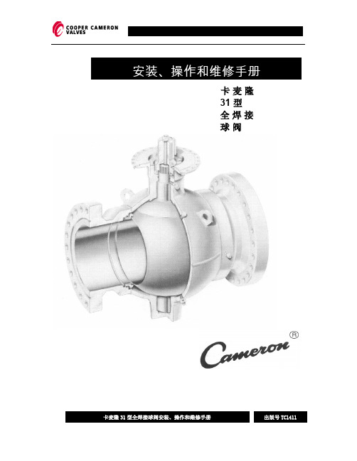
安装、操作和维修手册
卡麦隆 31 型 全焊接 球阀
焊接说明:
在预热、焊接或热应力释放时,距焊缝 3”(75 毫米)以外阀体上的任何点处温度均 不能超过 400 °F(200°C〕。请用测温色笔检验温度。
在把卡麦隆球阀最终焊接在管线之前,应用 1”宽的保护带盖上阀门密封 自三点钟 至九点钟区域(阀球与阀座之间的密封和阀座与端部之间的密封〕。这样有助于防 止任何杂质落入这个区域。在开工或试压之前,管线系统应通球清除杂质。
铭 牌 信 息:
序号 1
2 3 4 5 6 7 8 9 10 11 12 13 14
铭牌标记 阀门公称尺寸 X 阀球实 际尺寸 允许使用的最高温度 允许使用的最低温度 阀体材料代号 阀座内嵌材料代号 部件装配编号 阀门长度 API 设计磅级 最大工作压力 最大操作压力 阀座材料代号 阀球材料代号 阀门装配系列号 生产日期
1. 确认阀门已处于全开或全关位置及执行器 适配的位置。
2. 根据阀杆及齿轮箱/执行器安装工具的不 同, 执行器有多个安装位置是可能的。如 果是这种情况,应首先确定客户希望的手 轮或执行器控制盘的方位,然后一次进行 安装。(推荐阀表面使用一薄层润滑 剂。〕
3. 一旦操作器(执行器〕安装完毕,应用螺 栓固定执行器。如果与螺栓孔没有对齐, 请轻轻打开或关闭执行器直至与阀门适配 法兰相匹配。如果不能操作执行器,应完 成设定限位器的步骤 2 和 3。
----------------------------------------------
法兰式电动球阀_安装说明书

VG12E5xx 系列法兰连接式电动调节球阀安装安装说明书说明书Code No. LIT-14-1352-5CNIssued December 31, 2006产品应用范围产品应用范围::VG12E5xx 系列法兰连接式电动调节球阀,共有DN65、DN80、DN100三种DIN 标准法兰尺寸,设计用于调节-18°C 至 120°C 的热水、冷冻水、50%的乙二醇溶液;或者170kPa、130°C 以下的饱和蒸汽的流量,以便适应加热、通风和空调(HVAC)系统的控制负荷的要求。
重要提示重要提示::VG12E5系列电动调节阀设计用于系列电动调节阀设计用于,,在常规在常规的的设备运行条件下行条件下,,控制热水或冷冻水的流量控制热水或冷冻水的流量。
对于对于那些因那些因VG12E5系列阀门的失效或误动系列阀门的失效或误动作作,会导致人员伤亡,被控制设备和其它财产损失的被控制设备和其它财产损失的情况情况情况,,应对系统应对系统增增设保护装置设保护装置。
如增设功能监视或报警之类的系统如增设功能监视或报警之类的系统,,以防止因VG 系列调节阀失效或误动作带来的损害系列调节阀失效或误动作带来的损害。
安装说明安装说明::对于水平方向的管路,VG12E5电动调节球,用于冷冻水或50%的乙二醇溶液时,其安装位置应平行于或高于管路的中线。
目的是防止阀体上的冷凝水流淌 到电动执行器上,或者渗入执行器内部,造成电器元件的损坏。
见图2和图3所示:这一系列的两通球芯调节阀,配用本公司生产的Johnson Controls® 的 M9100系列非弹簧复位电动执行器、或M9200系列弹簧复位电动执行器。
电动执行器有开关式、浮点式或比例式三种控制方式。
电动调节球阀的阀体阀体阀体与相应的电动执行器电动执行器电动执行器及其连接件连接件连接件,要在现场进行组装现场进行组装现场进行组装。
重要提示重要提示::当VG12E5系列电动系列电动调节阀用于调节阀用于调节阀用于控制控制控制蒸汽蒸汽蒸汽的流量的流量的流量时时,在选定阀门的安装位置时在选定阀门的安装位置时,,要确保调节阀的阀杆要确保调节阀的阀杆要要处于水平位置处于水平位置。
球阀、截止阀、截止止回阀安装、使用及维护说明
球阀、截止阀、截止止回阀等阀门安装、使用及维护说明嘉兴市亚一达特种钢铸造有限公司一、产品搬运及储存1、运输起吊时不得翻转、倒放。
吊装过程应注意缓慢、平稳、轻放。
开箱后依次有序清理出阀门并存放于干燥的室内。
2、储存产品长时间存放时,应放于干燥的室内,并封闭进、出口两端。
注:阀门产品禁止露天存放。
二、产品安装及注意事项1、安装前应核对阀门上铭牌参数是否符合使用要求,阀门不应安装在实际使用压力超过其额定工作压力的管道上。
安装时必须注意阀体上的介质流向。
2、阀门安装位置不应防碍设备、管道及阀门本身的拆装和检修,应该留有足够空间。
阀门安装高度应方便操作和检修和维护。
3、安装前要检查阀门内腔、法兰密封面等部位,不得有污物或颗粒,清理阀体通道,检查各部位有无损坏现象,各零部件联接螺栓是否紧固。
正确安装后,做好必要防护,禁止用阀门校正管道的错位。
安装后检查所有螺栓是否紧固,以防止法兰密封端面渗漏。
4、安装前必须要彻底清除管道内的杂物,阀门运行前必须彻底冲洗管道。
阀门进口端必须安装过滤器,防止机械硬性等其他杂物损坏阀座密封面,否则会造成阀门内漏。
5、阀门手轮、手柄均不允许作起吊用,阀门安装、拆卸时不允许强烈碰撞。
阀门应在关闭状态下安装。
6、并排管线上设计安装阀门,其手轮间净距不得小于100mm,为了减小管道间距,并排布置的阀门最好错开布置。
7、阀门法兰连接时应保持平行,其偏差不大于法兰外径的1.5‰,且不大约2mm。
不得用强紧螺栓的方法消除偏斜。
8、法兰连接时应保持同一轴线,其螺孔中心偏差一般不超过孔径的5%,并保证螺栓自由穿入。
9、法兰连接应使用同一规格螺栓,安装方向一致,紧固螺栓应对称均匀,松紧适度,紧固后外露长度不大于2倍螺母厚度。
螺栓紧固后,应与法兰紧贴,不得有楔缝。
需要加垫圈时,每个螺栓所加垫圈不应超过一个。
10、法兰垫片应符合标准,不允许使用双层垫片。
11、高温或低温管道法兰连接螺栓,在试运转时一般应进行热紧或冷紧。
V800系列球阀安装与维护手册说明书
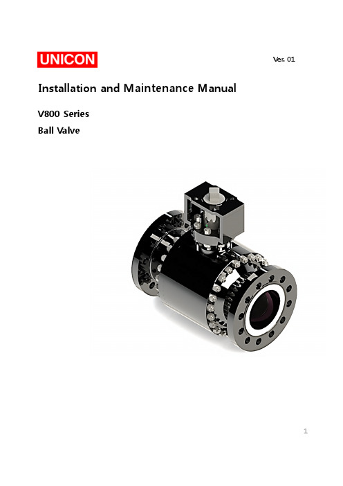
Installation and Maintenance ManualV800SeriesBall ValveVer.011Installation&Maintenance ManualTable of Contents1.Introduction2.Pre-Inspection3.Installation4.Operation5.Maintenance6.Disassembly/Reassembly7.Storage8.Packing9.Transport21-2Personnel qualification Transport,installation,commissioning,maintenance or repair must only be performed by trained or instructed personnel.WarningIn order to ensure successful and safe operation of our valves the entire operation manual must have been read through and understood prior to installation and commissioning.Under certain operating conditions,the use of damaged equipment could cause a degradation of the performance of the system which may lead to personal injury or death.If you have any questions about problems arise,contact UNICON office.Installation &Maintenance ManualTrunnion-Mounted Ball Seat RingSeat InsertSpring1-3Principle of OperationThe main function of the Trunnion Mounted Ball Valve is to cut off or connect the flow of fluid in a pipeline system.Via the manual hand wheel or other driving device,application of torque force allows the ball to rotate 90degrees,enough to align the ball bore to the centerline passage of the ball valve body,thus allowing fluid to pass through it.2.Pre-InspectionBefore installation of valve to the ‘Pipe Line’,it is recommended to inspect a valve closely as below.4Installation&Maintenance Manual2-1.Inspecting Valve&Accessory-Ensure any damage that might be occurred during the transportation.-Remove the protection cover of valve just before installation and clean a dust or harmfulparticles with an air blaster or smooth dust cloth/clean towel.-Check the tightness of all kinds of bolts and nuts.2-2.Inspecting Pipeline-Remove foreign materials such as a rust,welding chip,etc,which remain in the pipe orflange.-Make sure the clearness of pipe flange and gasket surface.Caution:When the fluid is flowing through the line,any foreign material is subject to scratch theseat and inner body,so that the scratch may cause leakage and shortening of the valvelifetime.To avoid product damage,inspect the valve before installation for any damage or anyforeign material that may have collected in the valve body.Also remove any pipe scale,welding slag,or other foreign material from the pipeline.3.InstallationIt is recommended to install valves on horizontal piping in a upright position.3-1Check the following items before valve mounting1.Service conditions should be within the valve specifications.2.Valve flanges should correspond with piping flanges.3.Gasket contact surfaces of pipes and valve flanges must be thoroughly inspected tomake sure no scratch or any other indication of flaw is found.4.The appropriate length should be kept between pipe flanges for the valve face-to-facedimensions including gasket thickness.5.The valve and pipe center should be aligned accurately.6.Bolt holes of flanges should be arranged symmetrically lined up against the center lineof flanges.57.Remove flange covers from valves just before installation.8.Check all stud bolts /nuts after installation and retighten them,if needed.Installation &Maintenance Manual Caution Before installation,the connecting pipes should be cleaned to remove any foreign object such as sand dust and welding spatters from the connecting pipe interior.CautionHandle valves carefully so that they may not fall or drop on the ground.Any extraordinary mechanical impact should be avoided.CautionPiping should be flushed before test operation,with valves open to assure removal of any foreign object that could damage valves.DO not operate valve during flushing.3-2Installation Procedure1.Make sure that pipes should be aligned accurately.2.The length between piping flanges should correspond with the valve face-to-face including gasket thickness.3.Place the valve between pipe flanges.Install two stud bolts at the bottom of the flanges lightly.4.Insert gaskets between valve and pipe flanges.5.Make sure the correct alignment of gaskets which are placed on bottom flange bolts between valve and pipe flanges.Figure 1.Installation6Installation&Maintenance Manual6.Stud bolts through the other bolt holes and tighten them lightly.7.Tighten bolts evenly,gradually and alternately in a star pattern as shown below.(See.Fig.2)The ends of all tightened bolts should protrude equally beyond the nuts.8.Raise the line temperature and pressure gradually on test operation Retighten the studbolts/nuts,if needed.Figure2.Flange Bolt Tightening SequenceWarningPersonal injury or system damage may result if the ball valve is installed where service conditions could exceed the limits given in the Specifications.Additionally,physical damage to the ball valve may result in personal injury or property damage due to escaping of accumulated fluid.To avoid such injury and damage,install the ball valve in a safe location.4.OperationThe valve is only intended to block or allow flow through the pipeline.The valve should only be used in either fully open or fully closed position.Do not use this valve to regulate flow by partially opening or partially closing the valve.The valve should not stay in a semi-open or semi-closed state for more than two minutes.Do not use the ball valve in process conditions where the pressure,temperature,media and other technical conditions exceeds the limitations set by the valve’s specification.WarningTo avoid possible personal injury,equipment damage,or leakage due to fluid,make certain the ball valve is installed as instructed in the Installation.7Installation &Maintenance ManualCaution 1.Wear the protective items such as goggle,gloves and working shoes.2.Take safely measures against the toxic,flammable or corrosive fluid.3.Reduce the line pressure to the atmospheric level before retightening packing gland and flange bolts and nuts.4.Operators should take protective measures to prevent direct exposure to the fluid.when the fluid spouts out from flange areas.5.Reduce theline pressuretotheatmosphericlevel,whenthe packing and gaskets arereplaced or bolts and nuts are loosened.Operator should take protective measures toprevent direct exposure to the fluid when the fluid spouts out from valves.6.Do not apply the lubricant to the pipes and valves which handle oxygen.Caution If the ball valve is equipped with test connection port,make sure that it is fully closedbefore pressurizing the valve.1.Check that proper installation is completed and any downstream equipment has beenproperly adjusted.2.Ensure that the pipeline system is free of foreign material before the startup.3.Make sure that the ball valve is fully turned to the open position before allowing fluidto pass through the valve.5.MaintenanceWarning Personal injury,equipment damage,or leakage due to escaping fluid may result if seals are not properly lubricated or maintained.Due to normal part wear or damage that may occur from external sources,ball valve should be inspected and maintained periodically.The frequency of inspection,maintenance,and replacement of parts depend upon the severity of service conditions or the requirements of local,state,and federal regulations.Ball valves that have been disassembled for repair must be tested for proper operationbefore returning it to service.In the maintenance process,take appropriate protective measures,such as wearing protective clothing,oxygenmasks,and gloves.Discharge the residual materials inside thevalve body before doing repair or maintenance.For electric,hydraulic or pneumatic valves,ensure that these lines are shut off before performing maintenance.8Installation &Maintenance ManualTrouble ShootingTrouble Possible Causes Remedial MeasureDisturbed valve operation Foreign objects mayhavechoked up the valve body cavity and stuck around the ball seat.Disassembleand inspect thevalve components.Excessive valve torque Foreign objects may have stuck to the stem.Remove the foreign object andcheck the valve Foreign objects may have choked up the valve body cavity and stuck around the ball seat.Flushthe valve bore with thefluid withthe valve slightly open to remove the built-upobjects or disassemble andinspect the valve The gland bolts may have been overly tightened.Once loosen thegland boltsand adequatelyretighten themto an extent that the leakage does not occur.Leakage from the packing box area Loose gland bolts.Retighten the gland bolts.Uneven tightening of the gland bolts.Onceloose the bolts andevenly retighten them.Damage on the packing part.Replace the packing part.Internal through-bone leakage Damage on the ball seats.Disassemble and inspect the valve Replace ball seats.Abnormal noise or vibration Loose bolts and nuts.Retighten the bolts and nuts.-Check the tightness of all nuts/bolts.-Regularly check if theball valve is set at the desired position whether fully open or fullyclosed.If the ball valve cannot be switched to either fully open or fully closed position,valve service is required.-Ensure the electrical continuity of the valve.(if needed)-Ensure that no leakage is being observed from the valve.-Frequent observation is recommended under extreme service condition.-It is advisable to maintain a record of the performance of the valve.-Mounting studs/nuts of the worm gearbox may be checked for tightness and retightened if necessary.-Do not use the valve as a ladder or pedestal when reaching equipment located above the valve.Do not hang additional weight to other related accessory of the valve.9Installation &Maintenance ManualFrequency of maintenance“Maintenance”means totally manage performance and function of valves and prevent from various damages.Frequency of maintenance depends on the below conditions.1.Shape of valve 2.Service temperature,class and materials used 3.External effects 4.Frequency of operate 5.Purpose of use 6.Maintenance methodsPart PurposeMethod ActionBody To Prevent for external leakage,seat leakage and wrong operation.Check the surface of seat and gasket for damages with the naked eyes.Overhaul REMARK :Repair by Lapping when the damage is small.If the damage of surface of seating and erosion are big,reprocess or replace it.Seat &Ball To Prevent for seat leakage and operation error.Check the surface of seat for damages with the naked eyes.Overhaul REMARK :Repair by Lapping when the damage is small.If the damage of surface of seating and erosion are big,reprocess or replace it.Stem To Prevent for external leakage and operation error. 1.Check scratches and seizing.2.Check the Gland packing-contact of stem for damage.Overhaul REMARK :If packing-contact of stem have damage or flexure or twisting,replace it.Bonnet Bolting To Prevent for loosing and separation of bolting and external leakage.Check the valve torque and tighten up bonnet bolting again if needed.Packing 1.To Prevent for operation error.2.To Prevent for external leakage by damage of stem.1.Check dry condition and cleanliness for threaded part of stem.2.If packing have damage,replace it.GasketTo Prevent for external leakage..Check loosing of bonnet bolting and tighten up it again if needed.REMARK :When valves are supplied to the client,it is optimal conditions that is satisfied with design requirements after inspection and test.But tightening of bolts can be affected by installation or test-run conditions.For the long operation,client definitely needs inspection as above to operate without leakage.Maintenance methods of valve10Installation&Maintenance Manual6.Disassembly/ReassemblyWarningTo avoid personal injury resulting from sudden release of pressure,isolate the ball valve from all pressure and cautiously release trapped pressure inside the valve chamber before attempting disassembly.Ensure that the middle chamber of the valve is fully depressurized before dismantling ormaintaining the valve.Pressure inside the pipe may be released,but the middle chambermay still have residual pressure.Open and close the valve several times to ensure that the pressure in the valve is completely released.If the media conveyed by the valve is toxic,inflammable,or explosive,make sure that there are no residual media left in the valveespecially in the middle chamber.Flush the valve with water or the appropriate cleaningsolvent to ensure the complete removal of the residual media.Open and close the valveseveral times while flushing the valve.Observe proper protective measures when dismantling the valve.If the media conveyed by the valve is toxic,inflammable,or explosive,always wear personal protective equipment to avoid any injury or accident.Keep the working site away from fire,sparks,or ignitionespecially if the media is combustible.To disassemble the valve,start disassembling with the last part as outlined in the assembly section.Place the dismantled parts on a soft mat.Do not allow it to have direct contactwith the ground.Mark the dismantled parts correctly to avoid confusion during the assembly.Do not dropor apply excessive force to the valve and its related parts to avoid damage or deformation of the components.if it will not be used for a long time,store the dismantled parts in asafe and dry area in order to protect it and prevent the formation of rust.6-1.Separation of Valve from the Pipe LineTo repair leaking valve,the valve must be removed from pipe line and then parts must be separated as below-Before removing the valve from the line,make sure that the line has been fully depressurized.-Drain all mediums from the pipe.-Remove the parts and remove the valve from the pipe.-Once the valve is removed,appropriate isolation of the pipe ends should be undertaken by the operator/contractor to prevent the creation of a combustible mixture where possible,and to prevent the introduction of dirt and debris into the system.-Mark the location of each part of valve and pipe in order to be installed at same places where they were.11Installation &Maintenance Manual6-2.Disassembly (See.Fig.4)-Unfasten the yoke bolt and then remove operator from body.-Refer to the appropriate operator instruction manual for actuator removal and replacement procedures.-Valve shall be positioned vertically by resting body side flanges on clean ground surface (preferably covered with rubber sheet).Ensuring no damage to the bottom /end face /threads as applicable.-Rotate the ball to fully open position.-Open the side flange joint by loosening the nuts in sequence.(See.Fig.2)Always tighten /loosen the bolts in flange bolt sequence.-Remove side flange,side flange gasket from body.-Remove O-ring or graphite(fire safety),spring,spring back-up ring from body.-Remove packing,packing box and packing flange by loosening bolt.-Remove bottom flange by loosening bolt.-Remove stem,ball,guide bush from body &side flange.-All the components should be stored in a clean place.Figure 3.Separation of Valve (RTJ Flange Type)FlangeMetal Ring Joint GasketValveMetal Ring Joint GasketFlange12Installation &Maintenance Manual6-3.Reassembly (See.Fig.4)-Body shall be positioned vertically by resting body side flanges on clean ground surface.(preferably covered with rubber sheet).-Apply suitable anti-seize grease to bolts.Warning Failure to properly follow the Assembly Instructions could result in ball valve damage,personal injury,and property.-Before reassembly,inspect the valve for any damage on side flange &all internals.-Ensure the cleanness of valve.-Damaged internals to be replaced by genuine &with recommended parts only.-New set of O-rings and gaskets shall be used once the valve is dismantled.-Assembly works in reverse order of disassembly.13Warning Failure to properly follow the Assembly Instructions could result in ball valve damage,personal injury,and property damage due to escaping process fluid during testing or after installing the ball valves in the pipe line.Before the performing the assembly work,clean all components of the ball valve and the working area.Ensure that there are no iron fi lings,rust,welding slag,and other debris inside the valve.keep all valve parts and the working area clean all throughout the assembly process.The working area must be padded with any soft material or mat.Do not allow the valve body,its components,or any of its assembled parts to have direct contact with the ground.Be careful with the lifting and moving of the ball valve’s components.Excessive force applied to the assembly may damage or deform the valve,its related parts,and its components which may cause the ball valve to malfunction.Installation &Maintenance ManualFigure 4.Ball Valve Assembly DrawingWrench boltWrench boltPacking BoxGasketPacking SetStem GuideStemGuide BushBearingBallSeat RingSpringSpring Back-up RingGasketStud &NutSide FlangeGasket Bottom FlangeStud &NutPacking FlangeO-ring or Graphite14Installation &Maintenance Manual7.StorageDuring storage,protect the valves from external effects and dirt.Avoid the formation of condensate through ventilation,desiccant or heating.Protect the connection openings to prevent entry of dirt or foreign matter.The storage room should be dry,dust-free and moderately ventilated.Storage temperature frost-free up to +25℃.8.PackingWarningValves that have come in contact with health-threatening media at the customer must be decontaminated prior to packaging.Valves that can be no longer be moved by hand must be transported with lifting equipment suitable for the weight to be moved.Transport the valves by using Eyebolts if available.Do not hook up lifting equipment to accessories such as hand wheels,control lines,pressure gages or flange bores.When using suspension belts,these must be placed around the valve body,providing edge protection and ensuring even weight distribution.Pack the valves so that any coatings or accessories such as plug-in devices,controllers and sensors cannot be damaged through subsequent transport.Protect connection openings to prevent the entry of e the packing material in accordance with the applicable regulations and observe country specific regulations.9.Transport15。
20K球阀门安装和操作手册说明书

Installation and Operation Manual20K Ball ValvesParker HannifinParker Hannifin (IPDE)Riverside Road, Barnstaple, Devon, EX31 1NP United KingdomTelephone: (01271) 313131E-mail:*****************************.comIDENTIFICATION OF HAZARDSNEVER adjust valves under pressure.NEVER slacken or remove any valve parts under pressure.NEVER use any mechanical aids i.e. wrenches, extensions to operate handles.NEVER carry valves by the handle.NEVER obscure valve body marking.NEVER remove end connectors.INSTALLATIONWear suitable PPE before installation and follow appropriate site safety procedures.Before installation, ensure that all valves are in the closed position.Phastite: Assembly instructions can be found in Catalogue 4235-PH & BULLETIN 5909Cone and Thread: Assembly instructions and Torques can be found in Catalogue 02-0124SE MPI: Assembly instructions can be found in Catalogue 4234-MACare should be taken to ensure that the end connector (9) is firmly held by an appropriate spanner / wrench (size varies depending on size of valve) to prevent any movement when assembling or disassembling connections.(See Catalogue 4190-HH/20K for full product offering)HANDLING AND STORAGEHandlingDo not lift or carry by the operating handles, as this may cause damage.StorageThere is no specified shelf-life.Boxed products should be stored in a covered area, preferably indoors, and away from excessive moisture, heat, or airborne contaminants.The use of desiccant or corrosion inhibitors is not required during normal storage periods.Installation and Operation Manual 20K Ball ValvesOPERATIONBall Valve:To close: Operate the handle (6) until it is at 90° from the valve body centreline.To open: Operate the handle (6) until it is in line with the centreline of the body and reaches the mechanical stop (3).Movement is limited to 90° by a mechanical stop.Ball valves should always be fully open or fully closed. Do not leave in a mid-position.MAINTENANCEParker 20K Ball Valves are supplied ready for service at their rated design pressure and should not normally require adjustment.Gland adjustment becomes necessary when the valve is visibly leaking via the gland adjuster (11).20K Ball Valve Gland Adjustment.CAUTION: Adjustment of the gland must be carried out at zero pressure1. Fully open the valve by operating the handle (6) until it is in line with the centreline of thebody.2. Unscrew Grub Screw (5) on handle (6) and remove handle from stem.3. Unscrew Socket Head Cap Screw (3) from Tru-Loc Plate and remove Tru-Loc Mechanism(4).4. Tighten Gland Nut (11) to 45 Nm5. Re-fit Tru-Loc plates (4) and secure in position with Socket Head Cap Screw (3) to 7.9 Nm.6. Re-fit handle (6) onto stem and secure into position with Grub Screw (5) to 9 Nm.1. BODY2. VALVE CONNECTIONS3. M6 SOCKET HEAD CAP SCREW4. TRU-LOC LOCKING MECHANISM5. M8 GRUB SCREW6. HANDLE7. HANDLE SLEEVE8. PANEL MTG. HOLE 9. END CONNECTOR 10. BRACKET MOUNTING HOLES11. GLAND ADJUSTER*HANDLE SHOWN AS SECTIONAL VIEW FOR CLARITYInstallation and Operation Manual20K Ball ValvesFURTHER INFORMATIONBall valve maximum Cv Value is 1.56 (Dependant on fitting size).For Panel Mounting of the 20K Ball Valve please follow the below:20K Needle Valve Panel Mounting.1.Unscrew Grub Screw (5) on handle (6) and remove handle from stem.2.Unscrew Socket Head Cap Screw (3) from Tru-Loc Plate and remove Tru-Loc Mechanism(4).3.Position valve body in panel and fasten into position with an M6 Socket Head Cap Screw(See Bolt Length note below) using mounting hole (8).4.Re-fit Tru-Loc plates (4) and secure in position with M6 Socket Head Cap Screw (3) Length20mm to 7.9 Nm.5.Re-fit handle (6) on to stem and secure into position with Grub Screw (5) to 9 Nm.20K Ball ValvesWARNING - USER RESPONSIBILITYFAILURE OR IMPROPER SELECTION OR IMPROPER USE OF THE PRODUCTS DESCRIBED HEREIN OR RELATED ITEMS CAN CAUSE DEATH, PERSONAL INJURY AND PROPERTY DAMAGE. This document and other information from Parker Hannifin Corporation, its subsidiaries and authorized distributors provide product or system options for further investigation by users having technical expertise.The user, through its own analysis and testing, is solely responsible for making the final selection of the system and components and assuring that all performance, endurance, maintenance, safety and warning requirements of the application are met. The user must analyse all aspects of the application, follow applicable industry standards, and follow the information concerning the product in the current product catalogue and in any other materials provided from Parker or its subsidiaries or authorized distributors.To the extent that Parker or its subsidiaries or authorized distributors provide component or system options based upon data or specifications provided by the user, the user is responsible for determining that such data and specifications are suitable and sufficient for all applications and reasonably foreseeable uses of the components or systems.。
球阀安装操作手册
球阀安装操作手册目 录前言 (1)一、 安装前的注意事项 (1)二、 安装过程中的操作规程 (1)三、 阀门的操作和维护 (5)四、 阀门的拆卸 (5)五、 故障处理 (14)球阀安装操作手册超达球阀安装操作手册前 言球阀的设计和制造是按照使用寿命长、无故障应用的要求进行并提供给客户的。
本手册给客户提供所有相关球阀安装、操作和长期使用维护的信息,所提供的图纸均为标准结构的图纸。
一、 安装前的注意事项1.阀门到达现场后,应仔细检查是否在运输途中受损。
2.在没有完成安装前,应保留阀门的包装和保护的设施。
3.如果阀门的通道以及法兰端面、对焊端等与管路安装有关的地方被裸露,应采取措施加以保护,以防止杂质进入阀门体腔。
4.阀门安装前,应检查和清洗管道,防止杂质如砂子、电焊渣等损坏球体和阀座表面。
5.如果阀门在安装使用前需要存放较长时间,应在阀门裸露表面涂上防锈油,并建议将阀门处于全开位置时存放在干燥和通风的地方,通道两端应上好闷盖保护。
长时间存放后安装使用该阀门,应先进行清洗,并重新试压,合格后投入安装使用。
6.手柄驱动的阀门,手柄指示的位置是阀门开关的标志,当手柄与管道的轴线平行时,阀门为开启,当手柄与管道的轴线垂直时,阀门为关闭。
二、 安装过程中的操作规程1.球阀可在除阀杆方向朝下的任何位置安装,建议安装阀门时将阀杆处于水平位置,严禁阀门倒装!2.阀门不应负载管道的重量。
对管道的支撑将因管道系统的震动造成阀门的变形,阀门可以通过在阀体上安装管道夹和支撑物进行支撑,不应在法兰上固定支撑物(如图7)。
3.不要通过法兰螺栓的调整来纠正管道的不平行。
4.不允许用阀门承载管道的重量来避免管线的扭曲和阻塞。
5.如有必要,在阀门试运行时应均匀压紧填料压盖。
6.合格的管道焊工必须按照ASME锅炉和压力容器标准第Ⅸ卷的规定进行焊接操作和评定。
7.在安装螺纹端、对焊端、承插焊端和法兰端连接阀门时,必须按照下列不同的程序和方法进行安装,以使阀门达到最佳的性能。
球阀安装维护手册..

铸钢球阀安装维护手册○本维护手册适用于公称通径不同而又没有特殊需要的同类产品。
○使用前请认真阅读维护手册。
前言本厂生产的软密封铸钢固定球阀,专门设计成密封可靠、使用寿命长、维护简单、维护成本低的一种新型产品。
同时,合适地以及规律的维护则可以最大限度的延长阀门的使用寿命。
目录1.用途和性能规范 (2)2.设计特点 (2)4.设计标准与规范 (4)5.阀门简图 (5)6.主要零件材料 (7)7.存储 (7)8.试验 (7)9.安装调试 (8)10.使用维护 (8)●用途和性能规范本阀门主要适用于天然气、油品等介质,并在管路中作启闭的装置。
具有流阻小、启闭迅速、启闭力矩小、全通径便于清扫管线等特点。
●设计特点a.阀体采用两体侧装或三体侧装结构,阀门内件经过精心选择,确保在各种工况下能可靠的工作。
阀门的壁厚和连接螺栓强度经过严密计算,符合美国标准ASME/ANSI B16.34的要求。
确保阀体的压力等级和连接的稳定性。
b.阀门为固定球结构,采用了具有自润滑衬PTFE的金属轴承,而且阀杆和球体可拆除,球体采用固定轴套支撑。
介质作用在球体上的力不会传递到阀杆上,避免了阀杆径向承受介质力。
球面和阀杆配合表面的光洁度高,减少摩擦力,降低了操作扭矩。
c.阀门处于关闭位置而且球体的一侧受压,阀体中腔内的高压介质(气体或液体)可以通过密封阀座自动往压力低的一端泄放。
d.双截断和排泄(DBB)功能,阀门处在关闭位置而且球体的两侧同时受压,阀体内腔的介质(气体或液体)可以从排泄阀泄放。
e.双活塞效应阀座设计(需要双活塞结构时):阀座的两侧在压力的作用下均可密封(即双活塞效应),双面密封阀座的特点在于:一旦上游阀座损坏而泄露,介质压力进入阀腔作用在下游侧,将阀座推向球体紧密接触,使下游阀座照样能密封。
这种双活塞效应阀座的球阀,阀体上应装有一个安全卸压阀以防止阀腔内介质因温度变化而产生超压的危险。
f.采用浮动阀座结构,阀座可以沿阀门的中轴线自由浮动。
球阀组装
球阀组装工作流程第一步:装“O”型圈工作方法:按要求把用硅油拌好的“O”型圈套在球杆上注意事项:1、装“O”型圈前先检查球杆处有无溢料,产品外观是否合格2、检查“O”型圈是否合格第二步:上手柄工作方法:按要求把手柄装在球杆上注意事项:1、装手柄前再次检查阀体外观是否合格2、检查手柄是否合格3、检查阀体球杆上是否已放好“O”型圈4、注意手柄方向,不要装反第三步:正手柄工作方法:把装好手柄的阀体放在正手柄机上,踩下脚踏开关,使气缸压在手柄上,转动手柄后抬起脚踏开关(φ75、φ90、φ110的用手电钻把自攻钉打到球杆上)注意事项:1、正手柄前检查手柄方向是否正确2、气缸压下时注意手不要放在手柄上或阀体下,阀体要放正,避免压手或阀体被压倒后压手5、转动手柄后检查是否正到位,到位为合格,否则手柄啃球杆,会造成商标盖或手柄处漏水,检查手柄是否压到位,“O”型圈是否外漏,外漏的不合格第四步:钉商标盖工作方法:按要求把商标盖钉到手柄上,钉完商标盖后把手柄转到关闭状态(φ75、φ90、φ110的先试压,后钉商标盖)注意事项:1、注意安全不要砸手2、把商标盖砸到位,端面不能高出手柄第五步:试压工作方法:把装好的球阀用试压机泡在水里试气压(气压标准8—10kg) 注意事项:1、手不要放正端口处,把住手柄中间位置,防止气缸压下时压手2、气缸压紧球阀进气管进气时,转动手柄至半开状态检查手柄和商标盖处是否漏气;如不漏气,再把手柄转到全开状态检查手柄和商标盖处是否漏气;如不漏气,再把手柄转到关闭状态后松开脚踏开关,把阀内灌上水检查两面球与止泻环接触处和止泻环与阀体接触处是否漏气,并打开手柄阀体内存气,不漏气的为合格;单面漏的需做对冲试验,两面均不漏气的为合格3、试压后,合格的第六步:包装工作方法:把试压合格的球阀洗净擦干后按要求包装,出口产品需在纸箱上粘贴唛头,包装完闭后入到指定的成品库注意事项:1、按要求使用合格的包装袋或纸箱2、保证包装物完好整洁3、包装前再次检查产品外观是否合格,把不合格的挑出附加有个别客户要求印字或粘贴标识的,需印完字或贴完标识后再包装,做到上一个工序对下一个工序负责,下一个工序对上一个工序监督。
- 1、下载文档前请自行甄别文档内容的完整性,平台不提供额外的编辑、内容补充、找答案等附加服务。
- 2、"仅部分预览"的文档,不可在线预览部分如存在完整性等问题,可反馈申请退款(可完整预览的文档不适用该条件!)。
- 3、如文档侵犯您的权益,请联系客服反馈,我们会尽快为您处理(人工客服工作时间:9:00-18:30)。
球阀安装、使用与维护保养标准手册
一、目的
为加强对公司内常用球阀的安装、使用与维护保养,保证球阀的长周期正常使用,特制订本标准操作手册。
二、适用范围
公司内车间员工。
三、术语解释
球阀:球阀的启闭件是个球体,球体绕阀体中心线作旋转来达到开启、关闭的一种阀门,在管路中主要用来做切断、分配和改变介质的流动方向,它只需要用旋转90度的操作和很小的转动力矩就能关闭严密;适用于低压、小口径管道上用于截断水流和改变水流的分配或需快速启闭的场所。
四、基本流程
五、工作指导 1、球阀安装前准备
1)安装前,确保前后管道同轴无扭曲。
如果是法兰连接,两法兰密封面必须平行。
当管道不能承受球阀的重量时,应在管道下部配有足以支撑管道和阀体的支撑。
球阀安装前准备
球阀的安装与使用
球阀的维护保养 球阀的维修
法
阀
球
规格
阀
锁定
前后管道同
轴,法兰密封面平
管道下部配有足以
支撑管道和阀体的支撑
2)必须把球阀前后的管线吹扫干净,清除管道内部的油污等一切杂物。
用抹布清除
密封面上的杂物
3)拆除球阀两端连接法兰上的保护件。
在不损伤密封
面的情况下拆除保
4)检查阀孔清除可能有的污物,然后清洗阀孔,但在安装前要保证水分已被完全干燥,污物全部都被清除,阀座与球之间即使仅有微小颗粒的异物也可能会损伤阀座密封面。
用抹布清除球
阀内部杂物,把水吹
5)核对球阀的标志和参数,检查球阀是否完好无损,将球阀全开全闭数次以保证其工作正常。
核对球阀的标志
和参数是否与管线适
2、球阀的安装与使用
1)把球阀装上管线,不能用执行机构作为起重的吊装点,避免造成执行机构及附件的变形或损坏。
2)阀法兰与管线法兰间按管路设计要求装上密封垫。
3)法兰上的螺栓需对称、逐次、均匀拧紧,并抹上黄油保养。
一人用手托住球
阀,另一人安装螺栓
安装缠绕好的垫
片并与密封面对齐
螺栓对角
安装,保证螺母
螺栓拧紧,并抹
上黄油保养
4)对管道与球阀间的法兰结合面进行密封性能检查。
5)开启、关闭球阀数次,灵活无滞涩,其工作正常。
6)安装完成后管道试压,观察法兰处无泄漏。
3、球阀的维护保养
1)阀门只做开关使用,不宜做调节使用;特别不允许在超越温度、压力界线和频繁交变压力工况条件下使用,高温时允许周期性拧紧螺栓以防泄漏,尽力减少热梯度。
2)运行中的阀门要每天检查和维护,严防锈蚀卡阻,要始终保持设备处于
观察密封面与垫片对齐,无泄漏
阀门关
阀杆顶部沟槽与管线平行阀门开
完好状态。
3)填料涵处外漏,检查填料是否压紧。
如用软质填料加注密封方式时,需再加注软质填料至不漏。
4)法兰处外漏,重新均匀拧紧螺栓一直不漏。
5)密封面内漏,检查是否关到位,密封面上是否有异物,在允许情况下打开阀门再关上看是否漏。
6)阀门检修时应重新清洗零件,清除异物,污渣和锈斑。
更换损坏的填料,垫片,修正密封面。
经检修、压力试验合格后方可再次投入使用。
4、球阀的维修
1)必须保证球阀上、下游管道确定已经卸除压力,才能进行拆卸维修操作。
2)拆卸及再装配时必须小心谨慎,防止损伤零件和密封面,尤其是非金属零件,取出O型密封圈时一定要使用专用的工具(尖锥、弯锥、曲锥、装配钩、镊子等)。
3)如果是法兰连接,重新装配时法兰上的螺栓必须对称、逐步、均匀地拧紧。
不可用力过轻,连接不严密,也不可用力过猛,以防脱丝。
4)清洗剂应与球阀中的橡胶件、塑料件、金属件及工作介质(例如燃气)等均相容。
工作介质为燃气时,可用汽油清洗金属零件。
非金属零件可用纯净水或酒精进行清洗。
5)分解下来的单个零件可以用浸洗方式清洗。
尚留有未分解下来的非金属件的金属件可采用干净的细洁的浸渍有清洗剂的绸布(为避免纤维脱落粘附在零件上)擦洗。
清洗时须去除一切粘附在壁面上的油脂、污垢、积胶、灰尘等。
6)非金属零件清洗后应立即从清洗剂中取出,不得长时间浸泡。
7)清洗后需待被洗壁面清洗剂挥发后(可用未浸清洗剂的绸布擦)进行装配,但不得长时间搁置,否则会生锈、被灰尘污染。
再重新装备前必须保证其干燥无污物。