计量阀(流量阀)世伟洛克MS-01-142[1]
世伟洛克 GU系列 通用针阀 说明书
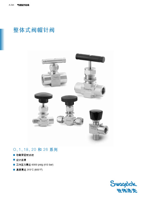
通用针阀 A-335A通用针阀GU 系列■ 直通型和角型■ 不锈钢和碳钢阀体材料■ 压力达到 6000 psig (413 bar)■ 使用 PTFE 填料时、温度可高达 232°C (450°F); 使用石墨填料时、温度可高达343°C (650°F)A-336 针形阀和计量阀A通用针阀 A-337A压力—温度额定值结构材料➀ 带焊接端接的阀体采用防锈涂层而不是镀锌。
流量数据测试所有世伟洛克 (Swagelok) GU 系列针阀都在工厂内使用 1000 psig (69 bar) 氮气进行过测试。
阀座的最大容许泄漏率为 0.1 std cm 3/分钟。
壳体测试时使用检漏液、达到未检测到泄漏的要求。
清洁和包装所有世伟洛克 GU 系列针阀都是按照世伟洛克标准清洁和包装规范 (SC-10)、MS-06-62 进行清洁和包装的。
角型旋转打开圈数流量系数 (C v )流量系数 (C v )直通型开启圈数与流量系数的关系曲线A-338 针形阀和计量阀A 订购信息与尺寸尺寸仅供参考、可能有变动。
直通型角型角型通用针阀 A-339A订购信息与尺寸尺寸仅供参考、可能有变动。
直通型A-340 针形阀和计量阀A 选购件欲订购带多个选购件的阀门、请按字母顺序添加相应代号。
高温阀杆填料、阀帽密封可提供石墨阀杆填料和阀帽密封材料来获得高达 343°C (650°F)的工作温度。
欲订购采用石墨材料的阀门、请在阀订购号中添加‑G。
示例: SS-4GUF4‑G防擅动手柄防擅动手柄降低了发生人为错误或故意改动的风险。
可以使用单独销售的防擅动钥匙操作这种阀门。
欲订购采用防擅动手柄的阀门、请在阀订购号中添加‑AT。
示例: SS-4GUF4‑AT圆形带锁手柄带锁手柄可以把阀门锁在任何位置。
4GU和 8GU 系列阀门的这种圆形手柄适合0.22 in. (5.7 mm) 以下的钩环直径、16GU系列阀门适合 0.28 in. (7.0 mm)以下的钩环直径。
世伟洛克 SK系列 多用途球阀 说明书

A-76 球阀A多用途球阀SK 系列■ 工作压力可达 6000 psig (413 bar)■ 温度范围从−40 到 150°C (−40 到 302°F)■ 使用紧凑型设计提供大流量能力■ 1/4 至 3/8 in. 和 6 至 8 mm 端接■ 316不锈钢结构SK 系列球阀 A-77A弹簧加载的■ ■ 漏密封压力—温度额定值可供应低温 SK 系列球阀。
见第 P A-79 页。
世伟洛克® (Swagelok ®) SK 系列球阀采用紧凑型设计、具有扭矩低、四分之一圈操作的特点、能够在压力最高达 6000 psig (413 bar) 的应用场合提供可靠关断。
其它特点还有:■ 流量系数 (C v ) 0.9 到 1.4■ 世伟洛克可测量卡套管接头、NPT 和 ISO 公称管以及世伟洛克外螺纹 VCO ®端接■ 标准面板安装 ■ 双向流动■ 可以使用密封成套件进行现场组装特点有关世伟洛克球阀的重要说明世伟洛克球阀设计用于全开或全闭位置。
在一段时间内未使用的阀门可能会有较高的初始启动力矩。
测试所有世伟洛克 SK 系列球阀都在工厂使用氮气在 1000 psig(69 bar) 的压力下进行了双流向测试。
阀座的最大容许泄漏率为0.1 std cm 3/min 。
壳体测试时要求用检漏液检测不到泄漏。
O 型圈阀杆密封■ ■ 清洁和包装所有世伟洛克 SK 系列球阀都是按照世伟洛克标准清洁和包装规范 (SC-10)、MS-06-62 清洁和包装的。
按照世伟洛克特殊清洁和包装 (SC-11)、 MS-06-63 进行的特殊清洁和包装作为可选项提供、以确保符合 ASTM G93 等级 C 中所规定的产品清洁度要求。
参阅第 P A-83 页的工艺选项。
卡套管数据、P G-5。
带有 VCO 管接头端接的阀的额定压力是基于与之配合的管 接头的额定值;见世伟洛克产品目录 VCO O 型圈面密封接头、P B-135。
世伟洛克针阀资料(中文)
➁ O、 20 和 1 系列带有 0.172 in. (4.4 mm) 孔口 — 2 双弹簧;
18、 26, 和 1 系列带有 0.250 in. (6.4 mm) 孔口 — 3 弹簧。
➂ 可调和 V 形阀杆尖和螺纹;软座阀杆螺纹。
测试
每个整体式阀帽针阀都在工厂用 1000 psig (69 bar) 下的氮进行 过测试。阀座的最大可允许漏泄率为 0.1 标准 cm3/min。壳体 测试是根据使用检漏液时无可探测出的泄漏的要求进行的。
O、1 和 18 系列
ASME 级别 材料级别 材料名称 温度,°C (°F) –53 (–65) 至 –28 (–20) –28 (–20) 至 37 (100) 93 (200) 121 (250) 148 (300) 176 (350) 204 (400) 232 (450) 260 (500) 315 (600) 5000 (344) 5000 (344) 4295 (295) 4085 (281) 3875 (266) 3715 (255) 3560 (245) 3435 (236) 3310 (228) 3130 (215) 2080 2.2 316 SS 铜 3000 (206) 3000 (206) 2350 (161) 2200 (151) 2050 (141) 1470 (101) 390 (26) — — — N/A N/A 钢 — 3000 (206) 2730 (188) 2695 (185) 2660 (183) 2615 (180) — — — — 工作压力,psig (bar) 3000 (206) 3000 (206) 2640 (181) 2555 (176) 2470 (170) 2430 (167) 2390 (164) 2380 (163) 2375 (163) — 1500 3.4 合金 400
世伟洛克阀门样本

62 系列—316 SS / A276; 63, 65 系列—黄铜 CDA 360 / B16
17 支承环 (2) 18 阀座 (2)
316 SS / A240, A276, 或 A479 加强型 PTFE ➃
19 锥形碟片弹簧 (2) 20 法兰密封 (2) 21 法兰 (2) 22 阀体紧固件 (4) 23 阀体六角螺母 (8 或 4)
其他阀座材料
阀门的阀座是...
还含有...
以及这些润滑剂
合金 X-750➀
S17400 SS 阀球➀ 和 316 SS 后阀座
硅脂基、氟化的二流化钨基 和 PTFE 基
碳 / 玻璃 PTFE PEEK➀➁
与带有 PTFE 阀座的阀相同
PEEK 阀杆支撑➀ 和填料➀
PTFE 基
UHMWPE
UHMWPE 填料, PEEK 阀杆支撑➀ 乙烯丙烯 O 形圈,
60 系列球阀
压力—温度额定值
压力-温度额定值是基于标准结构材料的,如同 4 上和以下表的 附注中所列出的那样。具有替代的结构材料的阀其额定值可能 不与所示出的相符。
对于带 CE 标记的 67 和 68 系列不锈钢 阀门,以 1.5 倍最大工作压力进行壳体 测试。
特殊用途阀
按特殊用途阀一节中所述,某些阀可能有 不同测试要求。
清洁和包装
每个 60 系列球阀均是按照世伟洛克标准 清洁和包装规格 (SC-10), MS-06-62 来 进行处理的。同样也可按照特殊清洁和包 装 (SC‑11), MS‑06‑63 来进行处理,以保 证满足 ASTM G93 等级 C 中所列出的产 品清洁度要求。详情请向您当地授权的世 伟洛克销售服务代表联系。
流体
在高压情况下,阀球被迫向下游,使下游阀座挠曲并产生密封。 上游阀座也随阀球运动而挠曲并保持密封。
世伟洛克swagelok40和40G系列一体式仪表球阀

上海别众实业有限公司 电话:021-59742356 传真:021-59747932 邮箱:mgd@ 网址:/
仪表球阀—40G 系列和 40 系列
303
目录
世伟洛克® (Swagelok®)仪表球阀 . . . . . . . . . . . . . . . . 303 有关世伟洛克仪表球阀 的重要信息 . . . . . . . . . . . . . . . . . . . . . . . . . . . . . . . . . 303 特点 . . . . . . . . . . . . . . . . . . . . . . . . . . . . . . . . . . . . . . 304 结构材料 . . . . . . . . . . . . . . . . . . . . . . . . . . . . . . . . . . . 305 压力—温度额定值 . . . . . . . . . . . . . . . . . . . . . . . . . . . 306 在 20°C (70°F) 时的流量数据 . . . . . . . . . . . . . . . . . . 306 测试 . . . . . . . . . . . . . . . . . . . . . . . . . . . . . . . . . . . . . . 306 清洁和包装 . . . . . . . . . . . . . . . . . . . . . . . . . . . . . . . . . 306 开关 (2 通) 阀门 . . . . . . . . . . . . . . . . . . . . . . . . . . . . . . 307 切换 (3 通) 阀门 . . . . . . . . . . . . . . . . . . . . . . . . . . . . . . 309 切换 (5 通和 7 通) 阀门 (40 系列) . . . . . . . . . . . . . . . . 311 交叉转换 (4 通和 6 通) 阀门 (40 系列) . . . . . . . . . . . . 312 手柄选购件 . . . . . . . . . . . . . . . . . . . . . . . . . . . . . . . . . 313 排放口和阀杆延长选购件 . . . . . . . . . . . . . . . . . . . . . . 315 附件 . . . . . . . . . . . . . . . . . . . . . . . . . . . . . . . . . . . . . . 315 气动执行机构 . . . . . . . . . . . . . . . . . . . . . . . . . . . . . . . 316 符合 ISO 5211 标准的气动执行机构 . . . . . . . . . . . . . 319 用于气动执行机构的选购件 . . . . . . . . . . . . . . . . . . . . 321 电动执行机构 . . . . . . . . . . . . . . . . . . . . . . . . . . . . . . . 322 工艺选项 . . . . . . . . . . . . . . . . . . . . . . . . . . . . . . . . . . . 323 服务选项 . . . . . . . . . . . . . . . . . . . . . . . . . . . . . . . . . . 323 流动路径选项 . . . . . . . . . . . . . . . . . . . . . . . . . . . . . . . 324 订购多种选购件和附件 . . . . . . . . . . . . . . . . . . . . . . . 328
世伟洛克 83系列和H83系列 耳轴球阀 说明书

耳轴球阀
压力 基于 所列出的阀座材料, 碳氟 FKM O 型圈和 加固的 PTFE 支撑环。 可供应低温 L83 系列球阀, 见第 8 页。
材料 阀座材料 温度,°C (°F) -17 (0) 至 37 (100) 65 (150) 93 (200) 121 (250) 148 176 204 232
耳轴球阀
8 3 系列和 H8 3 系列
■ 工作压力可达 10 000 psig (689 bar) ■ 1/8 至1/2 in. 和 6 至 12 mm 世伟洛克 (Swagelok) 卡套管接头或 NPT 端接 ■ 316 不锈钢材料
耳轴球阀
特点
■ 结构紧凑、 最大流量设计 ■ 低操作力矩 ■ 2 通或 3 通流通路径 ■ 面板安装 ■ 可提供气动和电动执行机构
H83 系列
H83 系列阀的压力 — 温度额定值是 基于 PEEK 阀座、 碳氟 FKM O 型圈和 加固的 PTFE 支撑环。 可供应低温 LH83 系列球阀, 见第 8 页。
材料 端接 温度,°C (°F) -17 (0) 至 37 (100) 65 (150) 93 (200) 121 (250) 148 176 204 232
83 系列 3 通
0.187 in. (4.75 mm) 孔径, 0.75 Cv
对大气压的压降 (p) psi (bar) 10 (0.68) 50 (3.4) 100 (6.8) 空气流量 std ft3/min (std L/min) 8.0 (220) 23 (650) 40 (1100) 水流量 U.S. gal/min (L/min) 2.4 (9.0) 5.3 (20) 7.5 (28)
— — 加固 PTFE
世伟洛克 LD 系列 隔膜阀 说明书
LD 系列隔膜阀 A-205A 隔膜阀LD 系列■ 工作压力高达 300 psig (20.6 bar)■ 开关、散装气体分配以及隔离服务■ 铸造、锻造及棒材不锈钢阀体材料■ 1/4 至 1 in.、12 至 25 mm 端接A-206 隔膜密封阀A可换隔膜/阀杆组件焊接隔膜结构■ 隔膜焊接到阀杆上、以防泄漏。
■ 三个隔膜实现强度、柔性和循环寿命的优化组合。
■ 设计实现流体的全金属包容。
独特的阀杆头设计■ PCTFE 阀杆头镶块有利于无泄漏的关闭。
■ 补偿阀杆头有助于防止由于过度紧固而造成的损坏。
特点■ 润湿区域无弹簧或螺纹、从而操作更加清洁。
■ 成型流道实现大流量。
■ 加固的隔膜设计实现有效的阀杆缩回。
联合阀帽的设计 可防止意外拆卸上部阀杆的位置显示阀门处于 开启还是关闭状态加固的隔膜实现有效的 阀杆缩回尺寸为 1/2 in. 尺寸为 1 in.阀体结构铸造 (尺寸为 1/2 和 1 in.)■ 阀体上机加工润湿表面的粗糙度 R a 平均为 20 µin. (0.51 µm)。
■ 提供可选的电抛光阀体外表面 (ELD 系列)。
■ 提供可选的内表面电抛光至粗糙度 R a 平均为 10 µin.(0.25 µm) 延长管。
锻造 (尺寸为 1/2 in.)■ 此种设计尺寸小、内部容积更少。
■ 润湿表面电抛光至 R a 平均为 5 µin. (0.13 µm)。
棒材 (尺寸为 1/2 和 1 in.)■ 阀门和管状组合成一个整体的、紧凑的部件。
■ 块式阀体实现散装气体系统的紧凑布局。
■ 润湿表面电抛光至 R a 平均为 5 µin. (0.13 µm)。
独特的夹环设计延长了循环寿命开启关闭关闭PCTFE 镶块LD 系列隔膜阀 A-207A1234567810119a9b9c9d 9e 9f9结构材料测试SC-11 工艺每个按照世伟洛克® (Swagelok ®) 特殊清洁及包装 (SC-11)、MS-06-63 进行处理的 LD 系列隔膜阀均进行了最大泄漏率为 4 3 10–9 std cm 3/s 的氦检漏测试。
世伟洛克 O、1、18、20 和 26 系列整体式阀帽针阀 说明书
孔口尺寸
■ 从 0.080 至 0.375 in. (2.0 至 9.5 mm)
A
流量系数 (Cv)
■ 从 0.09 至 1.80
流动形态
■ 直通、角型和十字型
面板装配
■ O、1 和 18 系列
动载荷密封系统
填料螺母使得 便利的外部调
整成为可能
可提供全面支撑的 填料减少了对调节
的需要
所显示的圆形手 柄;条形手柄可 提供
0.73
0.250 (6.4)
SS-1RS6 SS-1RS8
2.58 (65.5)
2.80 (71.1)
1.29 (32.8) 1.40 (35.6)
1.79 (45.5)
1.90 (48.3)
0.55 (14.0)
0.50 (12.7)
1.88 (47.8)
0.78 (19.8)
2.97 (75.4)
1.94 (49.3)
0.98 (24.9)
1.29 (32.8)
0.31 (7.9)
1.00 (25.4)
0.48 (12.2)
2.28 (57.9)
6 mm
0.37
公制
8 mm
世伟洛克 管接头
10 mm
0.73
12 mm
0.172 (4.4)
SS-1RS6MM SS-1RS8MM
0.250 (6.4)
尺寸单位为英寸 (毫米)、这些尺寸仅供参考、并可变更。
F 直通型
H 打开
G 板孔
板装厚度 1/8 至 1/4 (3.2 至 6.4)
流量系数 (Cv)
0.080 in. (2.0 mm)
0.080 in. (2.0 mm)
MS-01-146 世伟洛克60系列球阀 60 Series Ball Valve
Ball ValvesGeneral Purposeand Special Application60 Seriess1/8 to 2 in. and 6 to 25 mm sizess Stainless steel, carbon steel, brass, and special alloy materials s On-off (2-way) and switching (3-way) valvess Compensating seat designs Live-loaded, two-piece stem packing260 Series Ball ValvesUnique coned-disc spring-loaded seat s compensates for seat wear, pressure, and temperature changes s reduces seat wear from pressure surges s seals regardless of flow directionSupport ringcontains the seat and protects against seat bulge, premature wear,and deformationSeatFlange sealprovides leaktight seal between flange and center bodyContentsPageFeatures . . . . . . . . . . . . . . . . . . . . . . . . . . . . . . . . . . . . . .2Materials of Construction . . . . . . . . . . . . . . . . . . . . . . . . . .4Testing . . . . . . . . . . . . . . . . . . . . . . . . . . . . . . . . . . . . . . . .5Cleaning and Packaging . . . . . . . . . . . . . . . . . . . . . . . . . .5Pressure-Temperature Ratings . . . . . . . . . . . . . . . . . . . . . .6Ordering Information . . . . . . . . . . . . . . . . . . . . . . . . . . . . .8DimensionsSwagelok ®Tube Fitting End Connections . . . . . . . . . . . .9Female Pipe Thread End Connections . . . . . . . . . . . . . .10Tube and Pipe Socket Weld Connections . . . . . . . . . . . .11Pipe Butt Weld Connections . . . . . . . . . . . . . . . . . . . . . .12Tube Extension End Connections . . . . . . . . . . . . . . . . . .13VCO ®and VCR ®Face Seal Fitting End Connections . . .13Sanitary Fitting End Connections . . . . . . . . . . . . . . . . . .14Mixed End Connections . . . . . . . . . . . . . . . . . . . . . . . . .14Special Application ValvesSteam . . . . . . . . . . . . . . . . . . . . . . . . . . . . . . . . . . . . . .15Thermal . . . . . . . . . . . . . . . . . . . . . . . . . . . . . . . . . . . . .16Fire . . . . . . . . . . . . . . . . . . . . . . . . . . . . . . . . . . . . . . . .17Chlorine . . . . . . . . . . . . . . . . . . . . . . . . . . . . . . . . . . . . .18All Welded . . . . . . . . . . . . . . . . . . . . . . . . . . . . . . . . . . .18Low Temperature . . . . . . . . . . . . . . . . . . . . . . . . . . . . . .19Rapid-Cycle Service . . . . . . . . . . . . . . . . . . . . . . . . . . . .19Options . . . . . . . . . . . . . . . . . . . . . . . . . . . . . . . . . . . . . . .20Rack and Pinion Pneumatic Actuators . . . . . . . . . . . . . . . .22Featuress Quarter-turn actuations Stainless steel, carbon steel, brass, and special alloys s Lever, oval, extended oval, and locking handless Variety of end connections in 1/8 to 2 in. and 6 to 25mm sizes s Pneumatic and electric actuatorss Mounting brackets and couplings to enable mounting ofISO 5211 standard actuatorss Optional vent portingOn-Off (2-Way) ValveBallConed-disc springOxygen Service HazardsFor more information about hazards and risks of oxygen-enriched systems, see the Swagelok Oxygen System Safety technical report, MS-06-13.Important Information About Packed Valvess Packing adjustment may be required during the valve’sservice life.s Swagelok ball valves are designed to be operated in a fullyopen or fully closed position.60 Series Ball Valves 3Directional stem flatsshow open or closed positionStem springscompensate for changesin pressure andtemperature, and wearGrounding springgrounds stem to providecontinuity for antistaticprotectionLive-loaded,2-piecechevron stem packings requires less operating torques improves performances compensates for stem wearHigh-strength stem bearingss provide smooth actuations eliminate galling betweenvalve stem and bodys resist wearBottom-loaded stems prevents stem blowouts enhances system safetySwitching (3-Way) ValveAll stainless steel switching ball valves incorporate many ofthe features of the on-off (2-way) design. The one-piece centerbody uses no welding and allows 180°actuation. Theswitching design allows the user to:s divert flow from a common inlet to one of two outletss block flow from one inlet port and bleed out the opposite port.Flexing seat design ensures leaktight seal in both low-and high-pressure systemsUnder low pressure, seals are created by the coned discspring-loaded seats pushing against the ball. Pressure isnot required to create a seal.Under high pressure, the ball is forced downstream, flexing thedownstream seat and creating a seal. The upstream seat alsoflexes with the ball movement and maintains a seal.460 Series Ball ValvesMaterials of ConstructionWetted components listed in italics.➀Special alloy materials available include alloy 400, alloy C-276, alloy 20, alloy 600, and titanium. Contact your authorized Swagelok sales and service representative.➁62 series—no upper stem spring and stop plate integral with handle.➂Valves assembled with pneumatic actuators contain a lock tab (not shown) to secure the nut to the stem.➃Additional materials available; see Additional Seat Materials,below.➄Coated with hydrocarbon rust-preventive compound.➅Coated with molybdenum disulfide with hydrocarbon binder. Alloy X-750—2 bearings; PEEK—1 bearing.➆Additional materials available; see Flange Seal Kits,page 21.➇62 series—material specification is ASTM A574.➈62 series—nuts are grade 4130 or 4140/ASTM A322 or A331.Additional Seat Materials➀Molybdenum disulfide coated.➁62 and 65 series—Grafoil®-lined coned-disc springs; 67 and 68 series—PEEK-lined coned-disc springs.60 Series Ball Valves 5141521201918171613121110987645321TestingPlastic-Seated ValvesEvery 60 series ball valve is factory tested with nitrogen at 1000 psig (69bar) or its maximum workingpressure if less than 1000psig (69 bar).Seats have a maximum allowable leak rate of 0.1 std cm 3/min.Shell testing with nitrogen at 1000 psig (69bar) or the maximum rated pressure if less than 1000psig (69 bar) is performed on 62, 63, and 65 seriesvalves to a requirement of no detectable leakage with a liquid leak detector.Shell testing with water at 1.5 times the maximum working pressure isperformed on 67 and 68 series valves.Special-Application ValvesCertain valves may have different testing requirements, as described in Special-Application Valves.Cleaning and PackagingEvery 60 series ball valve is cleaned in accordance with Swagelok standard cleaning and packaging specification (SC-10). Cleaning and packaging in accordance with Special Cleaning and Packaging (SC-11)to ensure compliance with product cleanliness requirements stated in ASTM G93 Level C is available.Contact your authorized Swagelok representative for more information.Metal-Seated Valves and 3-Way PEEK-Seated ValvesEvery 60 series ball valve is factory tested with nitrogen at 50psig (3.4 bar)for leaktight integrity of the seats as specified by FCI 70-2 Specification Class VI.Shell testing with nitrogen at 1000 psig (69bar) or the maximum rated pressure if less than 1000psig (69 bar) is performed on 62, 63, and 65 seriesvalves to a requirement of no detectable leakage with a liquid leak detector.Shell testing with gas at 1.5 times the maximum working pressure isperformed on 67 and 68 series valves.2322660 Series Ball ValvesPressure-Temperature RatingsPressure-temperature ratings are based on standardmaterials of construction, as listed on page 4 and in the table notes below. Ratings for valves with alternative materials of construction may not match those shown. For example,Reinforced PTFE Seats (60T Series)Ratings based on reinforced PTFE seats and packings and alloy X-750 stem bearings on stainless steel or steel, PEEK stem bearings on brass, and fluorocarbon FKM O-rings.Fastener materials: 316 SS on stainless steel valves and carbon steel grade 8 on steel or brass valves.Steel valves with Swagelok tube fitting end connections: 375°F (190°C) max.Alloy X-750 Seats (60M Series)Ratings based on alloy X-750 seats and stem bearings, reinforced PTFE packings, and fluorocarbon FKM O-rings.Fastener materials: 316 SS on stainless steel valves and carbon steel grade 8on steel valves.Steel valves with Swagelok tube fitting end connections: 375°F (190°C) max.Carbon/Glass PTFE Seats (60C Series)Ratings based on carbon/glass PTFE seats, reinforced PTFE packings, and alloy X-750 stem bearings on stainless steel or steel; PEEK stem bearings on brass;and fluorocarbon FKM O-rings.Fastener materials: 316SS on stainless steel valves and carbon steel grade 8 on steel or brass valves.Steel valves with Swagelok tube fitting end connections: 375°F (190°C) max.2-way, stainless steel 67 and 68 series valves with reinforced PTFE seats are rated at 2200 psig at 100°F (151 bar at 37°C)when assembled with optional cadmium-plated carbon steel grade 8 fasteners.60 Series Ball Valves 7 PEEK Seats (60P Series)Ratings based on PEEK seats, packings, and stem bearings,and fluorocarbon FKM quad-seal flange seals.Fastener materials: 316 SS on stainless steel valves and carbonsteel grade 8 on steel or brass valves.Steel valves with Swagelok tube fitting end connections: 375°F(190°C) max.Polyethylene Seats (60E Series)Ratings based on UHMWPE seats and packings, PEEK stem bearings, and ethylene propylene O-rings.Fastener materials: 316 SS on stainless steel valves and carbon steel grade 8 on steel or brass valves.Steel valves with Swagelok tube fitting end connections: 375°F (190°C) max.Virgin PTFE Seats (60V Series)Ratings based on virgin PTFE seats and packings and alloy X-750 stem bearings on stainless steel or steel, PEEK stem bearings onbrass, and fluorocarbon FKM O-rings.Fastener materials: 316 SS on stainless steel valves and carbon steel grade 8 on steel or brass valves.Steel valves with Swagelok tube fitting end connections: 375°F (190°C) max.Ordering InformationOn-Off (2-Way) ValvesSelect an ordering number from the Dimensions tables starting on page 9.See the table below for availability of other valve body materials. To order, replace SS with B or S. Examples: B-62TS4S-62TS4860 Series Ball ValvesAdditional Seat MaterialsMost valve ordering numbers specify reinforced PTFE seat material. For other seat materials, replace T with the desired designator.Examples: SS-62P S4S-62E S4Switching (3-Way) ValvesSwitching (3-way) valves are available with:s stainless steel valve body materials standard or low-temperature services all seat materials except alloy X-750s bottom end connections shown below at right.To order a switching (3-way) valve with three of the same end connections,insert X into the valve ordering number. Example: SS-62X TF4To order a switching (3-way) valve with a different bottom end connection,insert X into the valve ordering number and add a bottom end connection designator.Example: SS-62X TF4-S4To order three different end connections,contact your authorized Swagelok representative.Cross-Port Mixing of FluidsA spherical ball is available in valves with UHMWPE or PEEK seats to prevent cross-port mixing of fluids. To order, insert O into the ordering number.Example: SS-62X O PF460 Series Ball Valves 9DimensionsDimensions, in inches (millimeters), are for reference only and are subject to change.Swagelok Tube Fitting End ConnectionsDimensions shown with Swagelok nuts finger-tight. See Ordering Information,page 8.Swagelok Hydraulic Swaging UnitWhen installing a Swagelok 60 series ball valve with tube fittings larger than 1 in., the Swagelok MHSU hydraulic swaging unit is needed. The unit swages the ferrules onto the tubing without applying stress to fitting body threads.See the Swagelok Multihead Hydraulic Swaging Unitcatalog, MS-02-154, for more information.All 67 and 68 stainless steel steam and thermal series valves and 67 and 68 series valves with UHMWPE seats are assembled with silver-plated front ferrules. All other 67 and 68 series stainless steel valves are assembled with PFA-coated front ferrules.➀Height and width of 63 through 68 series flanges. Height of 62 series flange is 1.59 in. (40.4mm); width is J dimension.1060 Series Ball ValvesFemale Pipe Thread End ConnectionsFemale NPT pipe thread dimensions conform to ASME B1.20.1. ISO tapered thread dimensions conform to ISO 7/1, EN 10226-1, DIN-2999, and JIS B0203. See Ordering Information,page 8.➀Height and width of 63 through 68 series flanges. Height of 62 series flange is 1.59 in. (40.4mm); width is J dimension.Steam Trap Test AssemblyDesigned for use with saturated steamsystems, the Swagelok TVA seriesintegrated test valve assembly consists of two 63 series ball valves and a universal mount for use with acustomer-supplied steam trap. The test assembly offers fast visual monitoring of condensate removal with a simple quarter turn of the test valve.Tube and Pipe Socket Weld End ConnectionsPipe socket diameter and depth conform to ASME B16.11. See Ordering Information,page 8.➀Height and width of 63 through 68 series flanges. Height of 62 series flange is 1.59 in. (40.4mm); width is J dimension.Swagelok Welding SystemsThe Swagelok welding system offersconsistent, repeatable orbital gastungsten arc welds (GTAW). It can be used to weld a variety of weld end connections available on Swagelok 60 series ball valves.Pipe Butt Weld End ConnectionsPipe butt weld end connections conform to ASME B16.25. See Ordering Information,page8.➀Height and width of 63 through 68 series flanges. Height of 62 series flange is 1.59 in. (40.4mm); width is J dimension.Tube Extension End ConnectionsTube extensions are available on stainless steel valves only. Tube extension material is 316L SS. See Ordering Information,page 8.➀Height and width of 63 through 68 series flanges. Height of 62 series flange is 1.59 in. (40.4mm); width is J dimension.VCO O-ring Face Seal and VCR Metal Gasket Face Seal Fitting End ConnectionsFace seal fitting end connections require minimal axial clearance for ease of installation and service.VCO fitting contains fluorocarbon FKM O-ring. See Ordering Information,page 8.VCO Fitting Pressure ratings of valves with VCR or VCO fitting end connections are based on the ratings of the mating fitting; see the Swagelok VCR Metal Gasket Face SealFittings or Swagelok VCO O-ring Face Seal Fittings catalogs, MS-01-24 and MS-01-28.➀Height and width of 63 series flange. Height of 62 series flange is 1.59 in. (40.4mm); width is J dimension.VCR FittingSanitary Fitting End ConnectionsValves with Swagelok TS and SC sanitary fitting end connections are available inmaterial and clamp used.a surface finish roughness average (R a )of 15 µin. (0.38µm). For more information, see the SwagelokBiopharm Fittings—TS Series catalog,MS-03-13.SC sanitary clamp end connections are ISO 2852 compatible.See Ordering Information,page 8.➀Height and width of 63 through 68 series flanges. Height of 62 series flange is 1.59 in. (40.4mm); width is J dimension.Mixed End Connections60 series valves can be ordered with two different end connections. Contact your authorized Swagelok representative for ordering information.TS Sanitary FittingsSC Sanitary Clamp Fittings➀Height and width of 63 through 68 series flanges. Height of 62 series flange is 1.59 in. (40.4mm); width is J dimension.Special-Application ValvesSteam Service (S60P Series)Steam service ball valves can reduce lost energy, downtime,and safety hazards associated with leaking valves in a steam system. Unlike conventional sealing methods, the patented designs of the seats and stem packing in the steam series ball valves resist the erosive nature of steam, thus improving performance and enhancing safety.Featuress Stainless steel or carbon steel materials.s PEEK (polyetheretherketone) seats and stem seals s resist absorption of waters resist erosive damage of steam.Grafoil flange seals maintain leaktight integrity at high temperaturesEncased 8-bolt constructionresists differential thermal expansionof body components during rapid temperature cyclingOrdering InformationTo order, insert S before the series designator and replace T with P.Example: SS-S 62P S4To order steel valve body material, replace SS with S.Example: S -S62PS4Wetted components listed in italics.All other components same as shown on page 4.➀S62P and S65P series —impregnated with hydrocarbon-based lubricant.➁S62P and S65P series —RTV silicone sealant.➂S63P series —contains no 316 SS.Materials of ConstructionPressure-Temperature RatingsSeal KitsSeal kits contain instructions and components of the materials listed in Materials of Construction.Kits contain stem springs, gland,packing support, packings, stem bearing, seats, seat springs, back sheets, flange seals, lubricant, and sealant.Select a kit ordering number.Saturated Steam RatingsStainless Steel Valves1050 psig at 550°F (72.3 bar at 287°C)Carbon Steel Valves680 psig at 500°F (46.8 bar at 260°C)Steel valves with Swagelok tube fitting end connections: 375°F (190°C) max.Thermal Service (T60M Series)The Swagelok thermal service ball valve, with its unique,spring-like metal seat, is designed to maintain a seal with a minimum seat load against the ball.Featuress 316 SS or carbon steel material with Grafoil packingand alloy X-750 seatss Resists contamination of the thermal liquid.s Enhances safety in thermal liquid systems.s Meets or exceeds FCI 70-2 Class VI for leaktight shutoff.s Exceeds performance requirements of Fire Test Standard API 607, 4th edition.Wetted components listed in italics.All other components same as shown on page 4.➀Coated with molybdenum disulfide with hydrocarbon binder.➁Impregnated with fluorocarbon-based lubricant.➂Impregnated with anaerobic adhesive. T63M and T65M series —RTV silicone sealant.Ordering InformationThermal series ball valves are available in 63, 65, 67, and 68series sizes. To order, insert T before the series designator and replace the second T with M.Example: SS-T 63M S8To order steel valve body material, replace SS with S.Example: S -T63MS8Smooth,quarter-turn rotary operation s resists outside contaminants s provides reliable containment of thermal liquidsUnique,spring-loaded metal seatss provide positive leaktightsealing at temperatures up to 850°F (454°C)s work equally well in low-and high-pressure systems.Materials of ConstructionEncased 8-bolt constructionresists differential thermal expansion of bodycomponents during rapid temperature cyclingSeal KitsSeal kits contain instructions and components of the materials listed in Materials of Construction.Kits contain ball, seats, packing, flange seals, stem bearings,back seats, packing supports, stem springs, lubricant, and sealant.Select a kit ordering number.Pressure-Temperature RatingsSteel valve ratings limited to –20°F (–28°C).Steel valves with Swagelok tube fitting end connections: 375°F (190°C) max.TestingAll thermal service ball valves are tested with pure nitrogen at 50 psig (3.4 bar) for leaktight integrity of the ball seats as specified by FCI 70-2 Class VI.Stem packing and body seals are tested for no visible leakage using a liquid leakGrafoil weir ringprovides seatseal against theball during fireconditions,even if only aportion of the seat isdestroyedLive-loaded Grafoilstem packingprovides a reliablestem seal duringnormal conditions andmaintains a seal in theevent of fireHigh-strength metalstem bearingsprovide smoothactuation, resist wearand extrusion, andmaintain packing loadin the event of fireGrafoil flange sealsprovide leaktight containment undernormal and fire conditions, eliminatingthe need for a secondary flange sealVented ballallows pressure to equalize between valve bodyand upstream port, preventing overpressurizationand potential seal blowout under fire conditionsEncased 8-bolt constructionmaintains body integrity and bodyseals during rapid temperaturechanges resulting from fire exposureand water quenchingCompensatingseat designlive loads the seat tocompensate for wear andchanges in temperatureor pressure during normalconditions and reducesdistortion of seats frompressure surgesFire Series (A60T Series)Fire series ball valves meet fire test specification API Standard 607, 4th edition.Materials of ConstructionOrdering InformationFire series ball valves are available in 63, 65, 67, and 68series sizes. To order, insert A in the ordering number.Example: SS-A63T S8To order steel valve body material, replace SS with S.Example: S-A63TS8TestingIn addition to the requirements given in Testing,page 5, fireseries ball valves meet those of API Standard 607, 4th edition,and Swagelok WS-166 Fire Test Specification. See theSwagelok Fire Series Ball Valves—A60T Series catalog,MS-02-47, for more details.Wetted components listed in italics.All other components same as shown on page 4.➀RTV silicone sealant on flange seals.Pressure-Temperature RatingsSteel valve ratings limited to –20°F (–28°C).Steel valves with Swagelok tube fitting end connections: 375°F (190°F) max.Seal KitsKits contain stem springs, gland,packing, packing supports, stembearings, seats with integral weirrings, seat springs, and flangeseals.Chlorine Series (C60V Series)Featuress Materials include carbon steel valve body with virgin PTFE seats and packing, in accordance with the guidelines of the Chlorine Institute Pamphlet 6, Piping Systems for Dry Chlorine.s Upstream ball vent prevents overpressurization in ball and body when valve is closed.Pressure-Temperature Ratings300 psig at –20 to 250°F (20.6 bar at –28 to 121°C).Cleaning and PackagingC60V series valve bodies and flanges are cleaned in mineral spirits followed by an aqueous cleaning solution containing a surfactant. All other wetted components are cleaned in accordance with Special Cleaning and Packaging (SC-11).C60V series ball valves are capped and sealed individually in desiccant packaging and are tagged for chlorine service.TestingEvery chlorine series valve is factory tested with nitrogen at 300psig (20.6 bar). Seats have a maximum allowable leak rate of 0.04 std cm 3/min.Shell testing with gas at 300 psig (20.6bar) is performed on 62, 63, and 65 chlorine series valves.Shell testing with gas at 1.5 times the maximum working pressure is performed on 67 and 68 chlorine series valves.Ordering InformationSelect an ordering number from the Dimensions tables for Swagelok tube fitting, female NPT, or tube and pipe socketMaterials of ConstructionAll-Welded Valves (W60T Series)FeaturesAll-welded ball valves incorporate the proven design features of the on-off (2-way)ball valve, all-welded body construction, and live-loaded packing to ensure total system fluid containment.TestingIn addition to the requirements given in Testing,page 5, a hydrostatic shell test is performed with pure water at 1.5times the working pressure.Dimensions and Ordering InformationDimensions in inches and (millimeters) are for reference only, subject to change.Select an ordering number.To order other seat materials, replace T C for carbon/glass PTFE, E for UHMWPE,or V for virgin PTFE.Example: SS-W63C F8Full penetration weld provides one-piece body construction for leaktight fluid containmentSeal KitsKits contain instructions, stem springs, gland, packing support,packings, stem bearing, seatsubassemblies, flange seals, and lubricant.Select a kit ordering number.Wetted components listed in italics.All other components same as shown on page 4.weld end connections. Insert C before the series designator.Replace SS and T with S and V,respectively.Example: S -C 62V S4Featuress Temperature rating –65 to 250°F(–53to 121°C).s Available in 2-way and 3-way 62, 63,and 65 series sizes in stainless steel and in 2-way 62, 63, and 65 series sizes in brass.s Available with seat materials shownin the table below.Ordering InformationT o order, insert L in the ordering number.Examples: SS-L 62TS4SS-L 62XTS4Seal KitsSeal kits contain instructions and components of the materials listed in Materials of Construction.See Seal Kits,page 21.Materials of ConstructionPressure-Temperature RatingsWetted components listed in italics.All other components same as shown on page 4.Wetted components listed in italics.All other components same as shown on page 4.➀Coated with molybdenum disulfide with hydrocarbon binder.Materials of ConstructionOrdering InformationTo order, insert R before the seriesdesignator in the valve ordering number.Example: SS-R 63TS8Pressure-Temperature RatingsSeal KitsSeal kits contain instructions and components of the materials listed in Materials of Construction.Kits contain stem spring, quad seal supports, spacer ring, stem quad seal,stem bearing, seats, seat springs,flange seals, and lubricant.Select a kit ordering number.See Pressure-Temperature Ratings,page 6, for ratings from 100 to 250°F (37 to 121°C).Valves for Low-Temperature Service (L60 Series)Valves for Rapid-Cycle Service (R60T Series)The quad seal-packed ball valve may be moreeffective in applications requiring rapid cycling of a valve or when packing adjustments may be difficult.Vented Valvess Allows vertical or horizontalmounting.s Can be installed on panelsup to 3/16 in. (4.8 mm) for 62 series and 1/4 in.(6.4mm) thick for 63, 65,67, and 68 series.s Fits oval and lever handle.s Provides template for drillingholes.Ordering InformationSelect an ordering number.For 4-Bolt Valves Assembled with Carbon Steel or Stainless Steel Bolts Kit includes self-cinching nut,cover plate, cap screws,panel mount brackets, two stainless and two carbon steel bolts, and instructions.Options and AccessoriesHandlesPanel Mount KitLow Dead Space Inserts s Reduce fluid entrapment around the ball, stem, and seatswhile the valve is in the open or closed position.s For use in select ball valves; not for use on steam, thermal,or fire series valves.s Made from carbon/glass reinforced PTFE.To order, add -LD to the valve ordering number.Examples: SS-62TS4-LD;SS-62XTS4-F8-LDKits for Field AssemblyFor 4-Bolt Valves Assembled with Stainless Steel Studs and All 8-Bolt Valves Kit includes self-cinching nut,cover plate, cap screws, panel mount brackets, and instructions.Vent PassageVent PassageExternal Vent OptionInternal Vent OptionLocking Lever Bracket Handle Oval HandleA variety of handle options is available for use with 60 series ball valves. To order a locking lever bracket handle, add -JL to the ordering number. To order an oval handle, add -JK to the ordering number. For additional information and dimensions,see the Swagelok Process Ball Valves Handle Options catalog,MS-01-137.On-off (2-way) ball valves are available with either an internal or an external vent. These vents are available for either upstream or downstream service. For details and ordering information, see the Swagelok Process Ball Valve Vent Options catalog, MS-02-28.。
世伟洛克FKB系列耳轴型中压球阀说明书
中压球阀FKB 系列世伟洛克 FKB 系列耳轴型球阀采用紧凑型设计,具有扭矩 低、四分之一圈操作的特点,能够在压力最高达 15,000 psig (1034 bar) 的应用场合提供可靠关断。
其它特点还有:■ 流量系数 (C v ) 为 0.44 到 11.3■ 可测的世伟洛克中压卡套管接头和内螺纹 NPT 端接 ■ 2 通(通-断)和 3 通(切换)流动方式■ 经检测的氮气阀座和经检测的外壳可确保产品完整性■ 位置可调的条形手柄和符合 ISO 5211 标准的气动执行机构■ 可选择手动阀面板和肩式安装。
压力—温度额定值欲了解关于带中压卡套管接头端接阀门压力额定值的更多信息,请参考世伟洛克产品目录中压可检测卡套管接头和转换接头,MS-02-335。
有关世伟洛克球阀的重要说明世伟洛克球阀设计用于全开或全闭位置。
在一段时间内未使用的阀门可能会有较高的初始启动力矩。
世伟洛克® 中压卡套管接头 端接:■ 减少阀门安装时间和费用■ 提供牢固的卡套管抓紧和 抗振动性能。
带有独特止动盘的位置可调 手柄:■ 提供元件布局灵活性,能够 减小系统占用的空间。
底部负载阀杆设计:■ 消除了阀杆冲出,提高了操作员安全性。
创新的阀杆密封设计 (正在申请专利):■ 在整个工作温度范围内保持全压力额定值耳轴球阀采用创新的直接负载设计:■ 能够在很宽压力范围内(即使在系 统卸压和重新加压条件下)保持一 致的密封■ 确保改善的控制系统执行的可靠 操作。
2 FKB 系列中压球阀结构材料4171015161819202124262930235961113121481722252327282-Way3-WayFKB 系列中压球阀 3测试每一个世伟洛克中压球阀生产厂中都使用氮气在 1000 psig(68.9 bar) 压力下进行测试。
阀座的最大容许泄漏率为0.1 std cm 3/分钟。
壳体测试是使用检漏液进行的,达到未检测到泄漏的要求。
- 1、下载文档前请自行甄别文档内容的完整性,平台不提供额外的编辑、内容补充、找答案等附加服务。
- 2、"仅部分预览"的文档,不可在线预览部分如存在完整性等问题,可反馈申请退款(可完整预览的文档不适用该条件!)。
- 3、如文档侵犯您的权益,请联系客服反馈,我们会尽快为您处理(人工客服工作时间:9:00-18:30)。
S 系列直通型 1.56 1.90 2.04 2.34 (59.4) 1.90 2.04
(39.6) (48.3) (51.8) (48.3) (51.8)
—
0.38
(9.6)
0.45
(11.4)
0.92
(23.4)
外螺纹 VCR 1/4 in. SS-SVR4 接头 1/16 in. 1/8 in. 世伟洛克 卡套管接头 1/4 in. 3 mm SS-SS1-A SS-SS2-A SS-SS4-A SS-SS3MM-A
最大流量 —— 0.16 Cv
至大气压 的压降 psi (bar) 10 (0.68) 50 (3.4) 100 (6.8) 空气流量 std ft3/min
(std L/min)
(35.1)
1.38
流量系数 (Cv)
水流量 U.S. gal/min
(L/min)
2.0 (56.6) 6.4 (181) 11.4 (323)
1
A
S 系列
M 系列 阀体材料 黄铜
L 系列 材料等级/ ASTM 规范 酚醛/D4617 镀镍镉钢 316 SS/A276 PTFE/D1710 316 SS/A276 440C SS/A276 316 SS/B783 316 SS/A276 316 SS/A479
316 SS 材料等级/ASTM 规范 300 SS/A276
316 SS/A182
带碳氢化合物载体的 镍防卡死剂
润滑剂
润湿元件用 斜体 表示。 ➀ 厌氧型粘结剂。 ➁ 直通型和双重型 M 系列阀。 ➂ 角 型和交叉型 M 系列阀门不包括阀体密封。
二硫化钼基;硅基
测试
每个世伟洛克S、 M和L系列计量阀都在工厂在 1000 psig (69 bar) 的条件下用氮气进行了测试.对壳体也按照检测不到泄 漏的要求用检漏液进行了测试. 每个世伟洛克L系列计量阀都在100 psig (6.8 bar) 的差压下进 行了无气泡阀座关闭测试. 世伟洛克的每一 31 系列针阀都在 1000 psig (69 bar)压力下进 行氮气测试。 阀座的最大容许泄漏率为 0.1 std cm3/min。
(std L/min)
SWAGELOK
B 所示为 M 系列阀。 S 系列 —— 最大面板厚度 0.16 in. (4.1 mm)。 M 和 L 系列 —— 最大面板厚度 0.13 in. (3.3 mm)。
流量系数 (Cv)
水流量 U.S. gal/min
(L/min)
0.33 (9.3) 0.90 (25构
20°C (70°F)时的流量数据
S 系列
开启圈数与流量系数的关系曲线 最大流量 —— 0.004 Cv
至大气压 的压降 psi (bar) 10 (0.68) 50 (3.4) 100 (6.8) 空气流量 std ft3/min
(std L/min)
订购信息
选择订购号。
S、 M 和 L 系列
2.06 (52.3) S 系列角型 3.22 (81.8) 0.81 3.32 (84.3) 3.36 (85.3) 3.32 (84.3) 0.98
(20.6) 0.88 (22.4)
A
0.38
(9.6)
A
G 面板孔 N
0.98 (24.9) 1.02 (25.9) (24.9) 0.99 (25.1) 0.98 (24.9)
尺寸
以 in. (mm) 为单位的尺寸仅供参考、 可 能有变动。
端接 进口/出口
尺寸
订购号 SS-SS1 SS-SS2 SS-SS4 SS-SS3MM SS-SS6MM
A
B
尺寸、in. (mm) D E
G
N
角型
E
1/16 in. 1/8 in. 世伟洛克 1/4 in. 卡套管接头 3 mm 6 mm
镀银雾铬黄铜 360/B16
涂黑色氧化层和轻油合金钢/ANSI 18.3 绿色阳极氧化铝 6061-T651/B211 涂黑色氧化层和轻油合金钢/ANSI 18.3 镀银雾铬黄铜 360/B16 316 SS/A479—S、M; 316 SS/B783—L 烧结 316 SS 316 SS/A479 316 SS/A479
0.45
(11.4)
0.92
(23.4)
外螺纹 NPT/ 1/8 in. SS-SM2-S2-A 3.07 (78.0) 世伟洛克 卡套管接头 1/8 in. 1/4 in. 3 mm 6 mm 1/8 in. 1/4 in. 1/8 in. SS-2MG SS-4MG SS-3MG-MM SS-6MG-MM SS-2MG2 SS-4MG2 SS-2MG4 M 系列直通型 2.02 2.20 2.02 2.20 2.78 (70.6) 1.50 1.96 1.94
锁紧螺钉 “锁住” 流量设定 (滚花和带槽手柄 )
阀杆螺纹 与系统流体隔离
A
VCR®
接头端接
导向 O 型圈加强阀杆 对准(仅用于S 系列) 锥形阀杆头 能准确地控制 气体和液体流量
手柄止动 有助于防止对阀 杆和孔径的破坏 阀杆 O 型圈 包含系统流体
技术数据
压力 — 温度额定值 温度 工作压力 °C (°F) psig (bar) –23 至 204 —碳氟 FKM O 型圈; –23 至 148 —丁腈橡胶 O 型圈
压力—温度额定值
额定值基于可选的 Grafoil® 填料。 使用 PTFE 填料时、 在 3435 psig (236 bar) 压力下额定值限于 232°C (450°F)。
ASME 等级 材料类别 材料名称 温度、°C (°F) –53 (–65) 至 37 (100) 93 (200) 148 (300) 204 (400) 232 (450) 260 (500) 315 (600) 343 (650) 371 (700) 398 (750) 426 (800) 454 (850) 2080 2.2 316 SS 工作压力、psig (bar) 5000 (344) 4295 (295) 3875 (266) 3560 (245) 3435 (236) 3310 (228) 3130 (215) 3080 (212) 3000 (206) 2930 (201) 2880 (198) 2815 (193)
开启圈数
手柄止动被设置在 15 psig (1.0 bar) 进 口压力下流量为 4 至 10 std cm3/min 时 使用。
A
调节手柄止动至较低的流量设置会
对阀和阀杆头造成损坏。
SWAGELOK
N
M 系列
开启圈数与流量系数的关系曲线 最大流量 —— 0.03 Cv
至大气压 的压降 psi (bar) 10 (0.68) 50 (3.4) 100 (6.8) 空气流量 std ft3/min
高压阀 (31 系列)
■ 流量系数 0.04; 孔径 0.062 in. (1.6 mm) ■ 316 SS 棒材阀体 ■ 直通型和角型 ■ 金属对金属的关断 ■ 2° 阀杆锥度 (包括角型) ■ 面板安装 ■ 圆形酚醛手柄 ■ 世伟洛克卡套管接头和内螺纹 NPT 端接
填料螺母 便于进行 外部调整 填料 完全容纳在 316 SS 填料压盖中以防止 挤出 金属对金属 关断
元件 1 手柄 固定螺钉 2 填料螺母 3 上压盖 4 填料 5 下压盖 6 阀杆 7 面板螺母 8 联合螺母 9 阀帽 10 阀体 润滑剂
元件 1a 手柄 手柄螺钉 锁紧螺钉➀ 1b 手柄 手柄螺钉 2 面板安装螺母 3 阀帽套管 4 阀帽 5 阀杆导环 6 阀体延伸部➁ 7 阀体密封件➂ 8 阀杆 O 型圈 9 阀体
镀银雾铬黄铜 345/B453
玻璃纤维填充 PTFE
镀银雾铬黄铜 345/B453 丁腈橡胶
S17400 SS/A564—S; 316 SS/A479—M、L
丁腈橡胶 镀银雾铬黄铜 377/B283
碳氟 FKM 镀硬质硌 S17400 SS/A564—S; 镀硬质硌 316 SS/A479—M、L 碳氟 FKM
0.51 (1.9) 1.2 (4.5) 1.7 (6.4)
0.38 (9.6) 最大面板 厚度
(91.4)
3.60
打开
0.59 (15.0) 面板孔
开启圈数
(27.7)
1.09
31 系列
开启圈数与流量系数的关系曲线 最大流量 —— 0.04 Cv
至大气压 的压降 psi (bar) 10 (0.68) 50 (3.4) 100 (6.8) 空气流量 std ft3/min
D
(51.3) (55.9) (51.3) (55.9) (38.1) (49.8) (49.3)
世伟洛克 卡套管接头
B
外螺纹 NPT
—
0.50
(12.7)
0.58
(14.7)
1.56
(39.6)
内螺纹 NPT 外螺纹 VCR 1/4 in. SS-MGVR4 接头 1/8 in. 1/4 in. 3 mm 6 mm 1/8 in. 1/4 in.
水流量 U.S. gal/min
(L/min)
对于黄铜 S、 M 和 L 系列阀、 用 B 取代 SS。 例: B-SS1 直通型
E
流量系数 (Cv)
0.04 (1.1) 0.10 (2.8) 0.20 (5.6)
0.01 (0.03) 0.02 (0.07) 0.04 (0.15)
G 面板孔
A
工厂流量设定
计量阀
A-345
计 量阀
A
S、 M、 L 和 31 系 列
■ 直通型流量系数 (Cv) 自 0.004 至 0.16 ■ 可用于低压和高压 ■ 可供应可重复游标刻度手柄 ■ 黄铜和 316 不锈钢材料