两相步进电机产品手册
两相数字式步进电机驱动器 HTD542 用户指南说明书
HT D542两相数字式步进电机驱动器使用前请认真阅读本手册用户使用手册常州合泰电机电器股份有限公司■ 简介● 两相数字式步进电机驱动器HTD542具有高速大转矩特性 供电电压可达 50VDC 静止时电流自动减半正弦波电流控制技术电机发热低● ● ● ● 光电隔离差分信号输入,响应频率最高200K 细分精度高达十六种,2倍及5倍细分均可选择具有过压、欠压,过流等保护功能可进行脉冲/方向或双脉冲模式切换● ●● HTD542两相步进电机驱动器是有极高可靠性的两相步进电机驱动器,是当前行业在售产品中返修率最低的一款产品。
得益于其优秀的过流和过压保护拓扑电路,使其即使在极高转速及适度过压情况下,仍可启动自保护以确保不被损坏。
HTD542两相步进电机驱动器适配两相42,57,60的各类两相混合式步进电机。
■ 电气性能及环境指标电气参数● 环境指标●驱动器参数最小值典型值最大值单位输入电压184850VDC 驱动电流 1.0- 4.2A 输入脉冲频率1-200K Hz 输入脉冲宽度250-5E+8ns 绝缘电阻500--M Ω冷却方式自然冷却或强制冷却使用场合避免粉尘,油污及腐蚀性气体工作环境温度0~40℃最高环境湿度90%RH (无结露)存储温度-10 ~70℃ 最大振动5.9m/S2 max■ 机械尺寸及安装图状态指示灯控制信号拨码开关设定电动机连接ENA -ENA+DIR -DIR +PUL-P UL+S W8S W7S W6S W5S W4S W3S W2S W1B -B+A+A -RED/GR ■ 驱动器接口与接线示意图电源及电机接线●● 控制信号接口控制信号示例图●名称功能GND -电源负极V+电源正极:DC18V ~50V A+两相电机A 相。
A+、A-互调,可变换电机运转方向A -B+两相电机B 相。
B+、B-互调,可变换电机运转方向B -名称功能PUL+脉冲控制信号:脉冲下降沿有效,脉冲电压5-24V,为了可靠响应,脉冲宽度大于1.5μS。
两相步进电机驱动器产品手册

两相步进电机驱动器产品手册1.产品介绍:1.1 产品概述:本章节介绍该两相步进电机驱动器产品的概览信息,包括产品的主要特点和应用领域。
1.2 产品规格:本章节详细介绍该步进电机驱动器的技术规格,包括输入电压、输出电流、步进角度等参数。
1.3 产品外观及接口:本章节描述该产品的外观特征以及接口定义,包括连接器类型、接口定义等。
2.安装与配置:2.1 安装步骤:本章节详细介绍该步进电机驱动器的安装步骤,包括硬件安装、接线和电源接入等。
2.2 配置参数:本章节介绍如何进行步进电机驱动器的参数配置,包括步数设置、步进角度调整等。
3.使用指南:3.1 驱动方式:本章节介绍两种常见的驱动方式,分别是全步进驱动和微步进驱动。
3.2 控制信号:本章节详细介绍控制信号的定义和使用方法,包括脉冲信号、方向信号等。
3.3 控制软件:本章节介绍常用的控制软件及其使用方法,包括设置步数、调整速度等。
3.4 常见问题解答:本章节了一些常见问题,并提供了相应的解决方案。
4.维护与保养:4.1 维护周期:本章节介绍了定期维护步进电机驱动器的时间周期,包括清洁、检查连接器等。
4.2 故障排除:本章节介绍了一些常见的故障现象并提供了相应的排除方法。
5.附件:本文档附带以下附件:●产品外观图●连接示意图●控制信号接口定义表6.法律名词及注释:在本文档中涉及的法律名词及其相关注释:●步进电机:一种电动机,它通过每次给定一个固定的角度脉冲就能转动一定角度的电动机。
●电流:通过导体中的电子流动而产生的一种物理现象。
●步进角度:步进电机每次转动的角度,通常为固定值(如1.8度)或可调节的微步角度。
青蓝 DM556 数字式两相步进驱动器使用说明书

DM556数字式两相步进驱动器一、产品简介1.概述DM556是青蓝科技新推出的数字式步进电机驱动器,采用最新32位DSP技术,用户可以设置200-25600内的任意细分以及额定电流内的任意电流值,能够满足大多数场合的应用需要。
由于采用内置微细分技术,即使在低细分的条件下,也能够达到高细分的效果,低中高速运行都很平稳,噪音超小。
驱动器内部集成了参数自动整定功能,能够针对不同电机自动生成最优运行参数,最大限度发挥电机的性能。
2.特点●全新32位DSP技术●可驱动4、6、8线两相步进电机●低振动低噪声●光隔离差分信号输入●内置高细分●脉冲响应频率最高可达200KHz(更高可改)●参数自动整流功能●电流设定方便,可在1.4-5.6A之间任意选择●精密电流控制使电机发热大为降低●细分设定范围为200-25600●静止时电流自动减半●具有过压、欠压、短路等保护功能3.应用领域适合各种中小型自动化设备和仪器,例如:雕刻机、打标机、切割机、激光照排、绘图仪、数控机床、自动装配设备等。
在用户期望小噪声、高速度的设备应用中应用效果特佳。
二、电气、机械和环境指标1.电气指标说明DM556最小值典型值最大值单位输出电流 1.0- 4.2A输入电源电压203650VDC控制信号输入电流71016mA步进脉冲频率0-200KHz绝缘电阻50MΩ2.使用环境及参数冷却方式自然冷却或强制风冷使用环境场合不能放在其他发热的设备旁,要避免粉尘、油雾、腐蚀性气体,湿度太大及强振动场所,禁止有可燃气体和导电灰尘温度0——50℃湿度40—90%RH 振动10~55Hz/0.15mm 保存温度-20℃~65℃重量280克3.机械安装图图1安装尺寸图(单位:mm)※推荐采用侧面安装,散热效果更佳,设计安装尺寸时,注意考虑端子大小及布线!4.加强散热方式1)驱动器的可靠工作温度通常在50℃以内,电机工作温度为80℃以内;2)建议使用时选择自动半流方式,马达停止时电流自动减一半,以减少电机和驱动器的发热;3)安装驱动器时请采用竖着侧面安装,使散热齿形成较强的空气对流;必要时机内靠近驱动器处安装风扇,强制散热,保证驱动器在可靠工作温度范围内工作。
东方电机公司2相步进电机和驱动器包装CSK系列说明书

ORIENTAL MOTORGENERAL CATALOG2-PHASE STEPPING MOTOR AND DRIVER PACKAGECSK SeriesFeatures·····························································B-234Standard Type····················································B-238High-Resolution Type·········································B-243SH Geared Type·················································B-248List of Motor and Driver Combinations···············B-253Wiring Diagram···················································B-254Switching and Setting Functions························B-255Adjusting the Output Current······························B-2552-PHASE STEPPING MOTOR AND DRIVER PACKAGECSK SeriesGEAR PLCDIRECTRE -GENER -ATION PACK - AGE DC INPUT1.High TorqueThe CSK high-torque 2-phase stepping motor series combines the PK series of 2-phase high-torque motors. The maximum holding torque values are as follows:CSK24Ⅺ: 22.2 oz-in (0.16N •m) ϳ44.4 oz-in (0.32N •m)CSK26Ⅺ:54.1 oz-in (0.39N •m) ϳ187 oz-in (1.35N •m)2.Powerful SH Geared TypeThe product line for the CSK series also includes the SH geared type that provides high torques. There are six gear ratios: 3.6:1, 7.2:1, 9:1, 10:1, 18:1, and 36:1.3.High-Resolution TypeThe product line for the CSK series also includes high-resolution types for which the basic step angle (1.8Њ/step) for the two-phase stepping motors is cut in half to 0.9Њ/step (for full steps).The resolution is doubled from 200 steps per revolution for standard types to 400 steps per revolution. The high-resolution type can be run in half-step mode to provide 800 steps per revolution.pact DriverThe drivers produce a high output of 2A/phase for 24V/36V DC. None the less, they are compact in size W 2.64 in.(67mm) ϫ D 2.83 in. (72mm) ϫ H 1.22 in. (31mm), due to a custom IC, surface mount technology and FET output stage.5.Expanded control functionsThese motors are equipped with an “Automatic Current Cutback ” function and “Excitation Timing ” output, which is handy for detecting the mechanical home position of the device.Furthermore, internal switches can set the step angle and pulse type.6.Simple and reliable connectionsIndependent connectors are used for the driver input/output signals and the motor output lines.7.Highly reliable photocoupler inputⅢCSK SERIES SYSTEM CONFIGURATION A compact stepping motor and driver are combined to make possible high-precision positioning with open loop control.2-Phase Stepping MotorCSK Series Standard Type(Full Step Angle 1.8˚)Page B-238Two sizes are available: the CSK24Ⅺ with a 1.65 inch (42mm)square mounting and the CSK26Ⅺwith a 2.22 inch (56.4mm)square mounting.CSK Series High-Resolution Type(Full Step Angle 0.9˚) PageB-243CSK high-resolution type has a full step angle of 0.9˚ (400 perrevolution).Two sizes are available: the CSK24ⅪM with a 1.65 inch(42mm) square mounting and the CSK26ⅪM with a 2.22 inch(56.4mm) square mounting.CSK Series SH Geared TypePage B-248Six gear ratios are available: 3.6:1, 7.2:1, 9:1, 10:1, 18:1 and 36:1.The low ratios allow the gear shaft speed to be reduced without reducing the speed of the motor too much, thus enabling more precise resolution and smoother rotation at low speed.ⅢSPECIFICATIONSSTANDARD TYPE (Full Step Angle 1.8°)motor torque performance. When using the motor with the dedicated driver, the driver's “Automatic Current Cutback ” function at motor standstill reduces maximum holding torque by approximately 40%.●The power source input current value represents the maximum current. (The input current varies according to the pulse frequency.)✽Responds up to approximately 10 kHz with a pulse duty of 50%. When using it at higher speeds, narrow the pulse width (shorten the photocoupler ’s ON time.)CSK 2 4 5 -A T AⅢPRODUCT NUMBER CODEShaft Type A : Single ShaftB : Double Shaft Motor Case Length2-phaseCSK seriesMotor Frame Size 4: 1.65 in. (42mm) sq.6:2.22 in. (56.4mm) sq.USA VersionTerminal Block TypeCSK243-BTANote:CSK244-BTACSK245-BTA●DC24V CSK243-BTACSK244-BTACSK245-BTA●DC36VT o r q u e [o z -i n ]T o r q u e [N ·m ]3.02.52.01.51.00.5 0D r i v e r I n p u t C u r r e n t [A ]2–72 Speed [r/min ](15)(150)(1500)(Half Step )0.300.250.200.150.100.050T o r q u e [o z -i n ]T o r q u e [N ·m ]3.02.52.01.51.00.5D r i v e r I n p u t C u r r e n t [A ]L 2(–72)Speed [r/min ](15)(150)(1500)(Half Step )0.300.250.200.150.100.050T o r q u e [N ·m ]3.02.52.01.51.00.5 0D r i v e r I n p u t C u r r e n t [A ]2(–72)Speed [r/min ](15)(150)(1500)(Half Step )T o r q u e [N ·m ]3.02.52.01.51.00.5 0D r i v e r I n p u t C u r r e n t [A ]L 2(–72)Speed [r/min ](15)(150)(1500)(Half Step )T o r q u e [N ·m ]3.02.52.01.51.00.5 0D r i v e r I n p u t C u r r e n t [A ]2(–72)Speed [r/min ](15)(150)(1500)(Half Step )T o r q u e [N ·m ]3.02.52.01.51.00.5D r i v e r I n p u t C u r r e n t [A ]2–72 Speed [r/min ](15)(150)(1500)(Half Step )CSK264-BTCSK266-BTCSK268-BT●DC24V CSK264-BTCSK266-BTCSK268-BT●DC36VT o r q u e [N ·m ]3.02.52.01.51.00.5 0D r i v e r I n p u t C u r r e n t [A ]2–72 Speed [r/min ](15)(150)(1500)(Half Step )T o r q u e [N ·m ]3.02.52.01.51.00.5D r i v e r I n p u t C u r r e n t [A ]L 2(–72)Speed [r/min ](15)(150)(1500)(Half Step )T o r q u e [N ·m ]3.02.52.01.51.00.5 0D r i v e r I n p u t C u r r e n t [A ]2–72 Speed [r/min ](15)(150)(1500)(Half Step )T o r q u e [N ·m ]3.02.52.01.51.00.5D r i v e r I n p u t C u r r e n t [A ]2–72 Speed [r/min ](15)(150)(1500)(Half Step )T o r q u e [N ·m ]3.02.52.01.51.00.5 0D r i v e r I n p u t C u r r e n t [A ]2–72 Speed [r/min ](15)(150)(1500)(Half Step )T o r q u e [N ·m ]3.02.52.01.51.00.5D r i v e r I n p u t C u r r e n t [A ]L 2(–72)Speed [r/min ](15)(150)(1500)(Half Step )Note:●MotorⅢDIMENSIONS scale 1/4, unitסinch (mm)CSK243-ATA(Single shaft)Motor Model: PK243-01AA Weight 0.47lb. (Mass 0.21kg) CSK243-BTA(Double shaft)Motor Model: PK243-01BA Weight 0.47lb. (Mass 0.21kg) CSK244-ATA(Single shaft)Motor Model: PK244-01AA Weight 0.6lb. (Mass 0.27kg) CSK244-BTA(Double shaft)Motor Model: PK244-01BA Weight 0.6lb. (Mass 0.27kg) CSK245-ATA(Single shaft)Motor Model: PK245-01AA Weight 0.78lb. (Mass 0.35kg) CSK245-BTA(Double shaft)Motor Model: PK245-01BA Weight 0.78lb. (Mass 0.35kg)CSK264-AT(Single shaft)Motor Model: PK264-02A Weight 1lb. (Mass 0.45kg) CSK264-BT(Double shaft)Motor Model: PK264-02B Weight 1lb. (Mass 0.45kg) CSK266-AT(Single shaft)Motor Model: PK266-02A Weight 1.55lb. (Mass 0.7kg) CSK266-BT(Double shaft)Motor Model: PK266-02B Weight 1.55lb. (Mass 0.7kg) CSK268-AT(Single shaft)Motor Model: PK268-02A Weight 2.21lb. (Mass 1kg) CSK268-BT(Double shaft)Motor Model: PK268-02B Weight 2.21lb. (Mass 1kg)✽.59Ϯ.01 (15Ϯ0.25) indicates the length of milling on motor shaft.● These external appearance drawings are for double shaft models. For a single. 2 5 0 0 D I A .1).25DIA.)).25DIA.✽.59Ϯ.01 (15Ϯ0.25) indicates the length of milling on motor shaft.✽.59Ϯ.01 (15Ϯ0.25) indicates the length of milling on motor shaft.ⅢDIMENSIONS scale 1/4, unitסinch (mm)●DriverDriver: CSD2109-T(For CSK243model)CSD2112-T(For CSK244and CSK245 models)CSD2120-T(For CSK264, CSK266 and CSK268 models) Weight: 0.29lb. (Mass 0.13kg).13DIA. ( 3.2)See page B-38 for information on driver installation.HIGH-RESOLUTION TYPE (Full Step Angle 0.9°)CSK 2 4 5 M A T AⅢPRODUCT NUMBER CODEShaft Type A : Single ShaftB : Double Shaft Motor Case Length2-phaseCSK seriesMotor Frame Size 4: 1.65 in. (42mm) sq.6:2.22 in. (56.4mm) sq.USA VersionTerminal Block TypeHigh-Resolution Type●Maximum holding torque refers to the holding torque at motor standstill when the rated current is supplied to the motor (2 phase excitation). Use this value to compare motor torque performance. When using the motor with the dedicated driver, the driver's "Automatic Current Cutback" function at motor standstill reduces maximum holdingⅢSPEED vs. TORQUE CHARACTERISTICS fs : Maximum Starting Pulse RateCSK243MBTACSK244MBTACSK245MBTA●DC24V CSK243MBTACSK244MBTACSK245MBTA●DC36VT o r q u e [o z -i n ]T o r q u e [N ·m ]3.02.52.01.51.00.5 0D r i v e r I n p u t C u r r e n t [A ]2(–72)Speed [r/min ](7.5)(75)(750)(Half Step )0.300.250.200.150.100.05T o r q u e [o z -i n ]T o r q u e [N ·m ]3.02.52.01.51.00.5D r i v e r I n p u t C u r r e n t [A ]2–72 Speed [r/min ](7.5)(75)(750)(Half Step )0.300.250.200.150.100.050T o r q u e [o z -i n ]T o r q u e [N ·m ]2.01.51.00.5 0D r i v e r I n p u t C u r r e n t [A ]2–72 Speed [r/min ](7.5)(75)(750)(Half Step )0.300.250.200.150.100.050T o r q u e [o z -i n ]T o r q u e [N ·m ]2.01.51.00.5D r i v e r I n p u t C u r r e n t [A ]L 2(–72)Speed [r/min ](7.5)(75)(750)(Half Step )0.300.250.200.150.100.05T o r q u e [o z -i n ]T o r q u e [N ·m ]2.01.51.00.5 0D r i v e r I n p u t C u r r e n t [A ]2–72 Speed [r/min ](7.5)(75)(750)(Half Step )0.300.250.200.150.100.050T o r q u e [o z -i n ]T o r q u e [N ·m ]2.01.51.00.5D r i v e r I n p u t C u r r e n t [A ]2(–72)Speed [r/min ](7.5)(75)(750)(Half Step )0.300.250.200.150.100.05Note:CSK264MBTCSK266MBTCSK268MBT●DC24V CSK264MBTCSK266MBTCSK268MBT●DC36VT o r q u e [o z -i n ]T o r q u e [N ·m ]2.01.51.00.5 0D r i v e r I n p u t C u r r e n t [A ]2–72 Speed [r/min ](7.5)(75)(750)(Half Step )0.60.50.40.30.20.10T o r q u e [o z -i n ]T o r q u e [N ·m ]2.01.51.00.5D r i v e r I n p u t C u r r e n t [A ]2–72 Speed [r/min ](7.5)(75)(750)(Half Step )0.60.50.40.30.20.1T o r q u e [o z -i n ]T o r q u e [N ·m ]2.01.51.00.5 0D r i v e r I n p u t C u r r e n t [A ]2(–72)Speed [r/min ](7.5)(75)(750)(Half Step )1.21.00.80.60.40.20T o r q u e [o z -i n ]T o r q u e [N ·m ]2.01.51.00.5D r i v e r I n p u t C u r r e n t [A ]2(–72)Speed [r/min ](7.5)(75)(750)(Half Step )1.21.00.80.60.40.2D r i v e r I n p u t C u r r e n t [A ]L 2(–72)Speed [r/min ](7.5)(75)(750)(Half Step )D r i v e r I n p u t C u r r e n t [A ]2–72 Speed [r/min ](7.5)(75)(750)(Half Step )Note:ⅢDIMENSIONS scale 1/4, unitסinch (mm)●MotorCSK243MATA(Single shaft)Motor Model: PK243MAA Weight 0.47lb. (Mass 0.21kg) CSK243MBTA(Double shaft)Motor Model: PK243MBA Weight 0.47lb. (Mass 0.21kg) CSK244MATA(Single shaft)Motor Model: PK244MAA Weight 0.6lb. (Mass 0.27kg) CSK244MBTA(Double shaft)Motor Model: PK244MBA Weight 0.6lb. (Mass 0.27kg) CSK245MATA(Single shaft)Motor Model: PK245MAA Weight 0.78lb. (Mass 0.35kg) CSK245MBTA(Double shaft)Motor Model: PK245MBA Weight 0.78lb. (Mass 0.35kg)CSK264MAT(Single shaft)Motor Model: PK264MA Weight 1lb. (Mass 0.45kg) CSK264MBT(Double shaft)Motor Model: PK264MB Weight 1lb. (Mass 0.45kg) CSK266MAT(Single shaft)Motor Model: PK266MA Weight 1.55lb. (Mass 0.7kg) CSK266MBT(Double shaft)Motor Model: PK266MB Weight 1.55lb. (Mass 0.7kg) CSK268MAT(Single shaft)Motor Model: PK268MA Weight 2.21lb. (Mass 1kg) CSK268MBT(Double shaft)Motor Model: PK268MB Weight 2.21lb. (Mass 1kg)✽.59Ϯ.01 (15Ϯ0.25) indicates the length of milling on motor shaft.. 2 5 0 0 D I A .1).25DIA.)1).25DIA.✽.59Ϯ.01 (15Ϯ0.25) indicates the length of milling on motor shaft.✽.59Ϯ.01 (15Ϯ0.25) indicates the length of milling on motor shaft.●DriverDriver: CSD2109-T(For CSK243M model)CSD2112-T(For CSK244M and CSK245M models)CSD2120-T(For CSK264M, CSK266M and CSK268M models) Weight: 0.29lb. (Mass 0.13kg).13DIA. ( 3.2)See page B-38 for information on driver installation.●Maximum holding torque refers to the holding torque at motor standstill when the rated current is supplied to the motor (2 phase excitation). Use this value to compare motor torque performance. When using the motor with the dedicated driver, the driver's “Automatic Current Cutback ” function at motor standstill reduces maximum holding torque by approximately 40%.●The power source input current value represents the maximum current. (The input current varies according to the pulse frequency.)●Permissible torque is the maximum value of the mechanical strength of the gear unit. Use the product with a total torque (load and acceleration) less than the permissible torque.ⅢSPECIFICATIONSSH GEARED TYPECSK 2 6 4 A T A -SG 10ⅢPRODUCT NUMBER CODEShaft Type A : Single ShaftB : Double ShaftMotor Case Length2-phaseCSK seriesMotor Frame Size 4: 1.65 in. (42mm) sq.6:2.22 in. (56.4mm) sq.USA VersionTerminal Block TypeSG : SH Geared TypeGear Ratio●Maximum holding torque refers to the holding torque at motor standstill when the rated current is supplied to the motor (2 phase excitation). Use this value to compare motor torque performance. When using the motor with the dedicated driver, the driver's "Automatic Current Cutback" function at motor standstill reduces maximum holding torque by approximately 40%.●The power source input current value represents the maximum current. (The input current varies according to the pulse frequency.)●Permissible torque is the maximum value of the mechanical strength of the gear unit. Use the product with a total torque (load and acceleration) less than the permissible torque.ⅢSPEED vs. TORQUE CHARACTERISTICSCSK243BTA-SG3.6CSK243BTA-SG7.2CSK243BTA-SG9CSK243BTA-SG10CSK243BTA-SG18CSK243BTA-SG36ⅢPRECAUTIONSWhen using the CSK SH geared type, please note the following:1.Do not exceed the maximumpermissible torque:Permissible torque represents the maximum value of themechanical strength of the gear unit. Be sure to keep the total 2.Do not exceed the permissible speedrange:Do not exceed the maximum output speed of the gearhead indicated in the specifications on page B-248, 249. The speedT o r q u e [N ·m ]1.41.21.00.80.60.40.20D r i v e r I n p u t C u r r e n t [A ]2–72 Speed [r/min ](4.16)(41.6)(416)(Half Step )T o r q u e [N ·m ]1.41.21.00.80.60.40.20D r i v e r I n p u t C u r r e n t [A ]2–72 Speed [r/min ](2.08)(20.8)(208)(Half Step )T o r q u e [N ·m ]1.41.21.00.80.60.40.20D r i v e r I n p u t C u r r e n t [A ]2–72 Speed [r/min ](1.66)(16.6)(166)(Half Step )T o r q u e [N ·m ]1.41.21.00.80.60.40.2D r i v e r I n p u t C u r r e n t [A ]2(–72) Speed [r/min ](0.83)(8.33)(83.3)(Half Step )T o r q u e [N ·m ]1.41.21.00.80.60.40.20D r i v e r I n p u t C u r r e n t [A ]2–72 Speed [r/min ](0.41)(4.16)(41.6)(Half Step )T o r q u e [N ·m ]1.41.21.00.80.60.40.2D r i v e r I n p u t C u r r e n t [A ]2–72 Speed [r/min ](1.5)(15)(150)(Half Step )fs : Maximum Starting Pulse RateNote:●Pay attention to heat dissipation from motor and driver. The motor will produce a considerable amount of heat under certain conditions. Be sure to keep the temperature of the motor case under 212˚F (100˚C).● When using the motor with the dedicated driver, the driver's "Automatic Current Cutback" function at motor standstil reduces maximum holding torque by approximately 40%.CSK264BTA-SG3.6CSK264BTA-SG7.2CSK264BTA-SG9CSK264BTA-SG10CSK264BTA-SG18CSK264BTA-SG36D r i v e r I n p u t C u r r e n t [A ]2(–72)Speed [r/min ](4.16)(41.6)(416)(Half Step )D r i v e r I n p u t C u r r e n t [A ]2(–72)Speed [r/min ](2.08)(20.8)(208)(Half Step )D r i v e r I n p u t C u r r e n t [A ]2–72 Speed [r/min ](1.66)(16.6)(166)(Half Step )D r i v e r I n p u t C u r r e n t [A ]2(–72) Speed [r/min ](0.83)(8.33)(83.3)(Half Step )D r i v e r I n p u t C u r r e n t [A ]2(–72)Speed [r/min ](0.41)(4.16)(41.6)(Half Step )D r i v e r I n p u t C u r r e n t [A ]2(–72)Speed [r/min ](1.5)(15)(150)(Half Step )4.The direction of gear shaft rotationsdiffers according to reduction ratios:The direction of motor shaft rotation and gear shaft rotation according to the gear ratio applied:3.Consider backlash in bi-directionalpositioning:Backlash is the free rotation angle (i.e., play) of the output shaft when the input section of the reduction gear is fixed. If there is a Note:●Pay attention to heat dissipation from motor and driver. The motor will produce a considerable amount of heat under certain conditions. Be sure to keep the temperature of the motor case under 212˚F (100˚C).● When using the motor with the dedicated driver, the driver's "Automatic Current Cutback" function at motor standstil reduces maximum holding torque by approximately 40%.CSK243ATA-SG Ⅺ(Single shaft)Motor Model: PK243A1A-SG ⅪWeight 0.78lb. (Mass 0.35kg)CSK243BTA-SG Ⅺ(Double shaft)Motor Model: PK243B1A-SG ⅪWeight 0.78lb. (Mass 0.35kg)CSK264ATA-SG Ⅺ(Single shaft)Motor Model: PK264A2A-SG ⅪWeight 1.66lb. (Mass 0.75kg)CSK264BTA-SG Ⅺ(Double shaft)Motor Model: PK264B2A-SG ⅪWeight 1.66lb. (Mass 0.75kg)✽.59Ϯ.01 (15Ϯ0.25) indicates the length of milling on motor shaft.See page B-36 for information on motor installation.ⅷScrews (included)4-No.4-40 UNC. length .39 (10)ⅷScrews (included)4-No.8-32 UNC. length .59 (15).1968 D I A .0.2500 D I A .[1/4"]●DriverDriver : CSD2109-T (For CSK243-SG model)CSD2120-T (For CSK264-SG model)Weight: 0.29lb. (Mass 0.13kg).13 DIA. ( 3.2)●MotorⅢDIMENSIONS scale 1/4, unit סinch (mm)● shaft, ignore the colored areas.Enter A(single shaft) or B(double shaft) in the Ⅺwithin the model numbers.ⅢWIRING DIAGRAMⅢINPUT/OUTPUT SIGNALSⅢPower Supply2-Phase Stepping Motor●Pulse Input1-Pulse Input Mode Pulse Signal"Pulse" signal is input to the PULSE/CW Ϫterminal. When the photocoupler state changes from "ON" to "OFF", the motor rotates one step. The direction of rotation is determined by the following rotation direction signal.Rotation Direction SignalThe "Rotation Direction" signal is input to theDIR./CCW Ϫterminal. A "photocoupler ON" signal input commands a clockwise direction rotation. A "photocoupler OFF" signal input commands a counterclockwise direction rotation.2-Pulse Input Mode CW Pulse Signal"Pulse" signal is input to the PULSE/CW Ϫterminal. When the photocoupler state changes from "ON" to "OFF", the motor rotates one step in a clockwise W Pulse Signal"Pulse" signal is input to the DIR./CCW Ϫterminal. When the photocoupler state changes from "ON" to "OFF", the motor rotates one step in a counterclockwise direction.●All Windings Off (C.OFF) InputWhen the "All windings Off" (C.OFF) signal is in the"photocoupler ON" state, the current to the motor is cut off and motor torque is reduced to zero. The motor output shaft can then be rotated freely by hand.This signal is used when moving the motor by external force or manual home position is desired.●Excitation-Timing (TIMING) OutputThe signal is output once each time the excitation sequence returns to step "0" in synchronization with input pulses. The excitation sequence is designed to complete electrical one cycle as the motor shaft rotates 7.2˚. A signal is output every 4 pulses in full step mode (1.8˚/step) and every 8pulses in half step mode (0.9˚/step).Use a power supply that can supply sufficient input current.When power supply capacity is insufficient, a decrease in motor output can cause the following malfunctions:●Motor does not rotate properly at high-speed (insufficient torque)●Motor startup and stopping is slow.Use connector TB1 and TB2 when connecting.Note:●Keep the voltage Vo 1and Vo 2between DC 5V and DC 24V. When they are equal to DC 5V, the external resistances R 1and R 2are not neccessory. When they are above DC 5V, connect R 1to keep the current below 20mA, and connect R 2to keep the current below 10mA.●Use twisted-pair wire of 3.1ϫ10-4 in 2(0.2mm 2) or thicker and 6.6 feet (2m) or iess in length for the signal line.●Use wire 7.8ϫ10-4 in 2(0.5mm 2) or thicker for motor lines (when extended) and power supply lines, and use 1.2ϫ10-3 in 2(0.75mm 2) or thicker for the wire for the grounding line.●Use spot grounding for the grounding of the driver and external controller. ●Signal lines should be kept away at least 3.94 in. (10cm) from power lines(power supply lines and motor lines). Do not bind the signal line and power line together.ⅢTIMING CHARTCW Motor CCWPulseAll Windings Off Input ON OFFON OFFON OFFDirection✽1 It is recommended to wait a period of time to allow the motor oscillations toend before inputting the "All windings Off" signal. This time varies with the load inertia, the load torque and the starting pulse rate, Signal input must be stopped before the motor stops.✽2 Never input a step pulse signal immediately after switching the "All windingsOff" signal to the “photocoupler ON ” state or the motor may losesynchronism. In general, an interval of 100ms (minimum) is required.Response up to about 10 kHz with a pulse duty of 50%. When using it at higher speeds, narrow the pulse width.2. Adjusting the Motor Operating CurrentTo set the "Automatic Current Cutback" function to inactive (SW1:OFF):(1) Adjust the motor operating current with the RUNpotentiometer. It can be adjusted from 0.3A/phase to the rated value of the driver.(2) The motor operating current is set for the rated current at the time of shipping. The RUN potentiometer can be used lower the operating current to reduce temperature rise in the motor/driver, adjust torque margin and reduce vibration.ⅢSWITCHING AND SETTING FUNCTIONS 3. Adjusting The Current At Motor StandstillT o set the "Automatic Current Cutback" function to active (SW1:ON):(1) Adjust the current at motor standstill with the STOPpotentiometer. It can be adjusted from 25% to 40% of the run operating current (0.3A minimum).(2) At the time of shipping, the current at motor standstill is set for 40%. The STOP potentiometer readjusts the current to the value required to produce enough holding torque.(1) Automatic Current Cutback at motor standstill When switch 1 (ACD) is set to ON, the "Automatic CurrentCutback" function at motor standstill is active. Approximately 0.1seconds after input pulses stop, the motor output current is automatically lowered to suppress heat generation in the motor and driver. Generally, the switch should be in the ON position. (If the switch is set to OFF , the "Automatic Current Cutback"function at motor standstill is disabled.)(2) Step Angle Standard Type:When switch 2 (F/H) is set to ON, the driver is set for 1.8˚/step (200 steps per revolution. When the switch is set to OFF , the driver is set for 0.9˚/step (400 steps per revolution). High-Resolution Type:When switch 2 (F/H) is set to ON, the driver is set for 0.9˚/step (400 steps per revolution). When the switch is set to OFF , the driver is set for 0.45˚/step (800 steps per revolution).(3) Pulse Input ModeThe driver is designed to function under either of the following two pulse output modes on the user ’s controller:●When switch 3 (1P/2P) is set to OFF , the driver is set for the 2-pulse input mode, in which two types of pulse signal (one each for CW and CCW) are used to control the motor.●When switch 3 (1P/2P) is set to ON, the driver is set for the 1-pulse input mode, in which a pulse signal and a direction of rotation signal are used to control the motor.(4) Power Supply VoltageWhen using a 24V DC power supply, switch 4 (24/36V) should be ON. When using a 36V DC power supply, the switch should be OFF .ⅢADJUSTING THE OUTPUT CURRENT1.Adjustment MethodConnecting voltmeterInsert voltmeter test probes [approximately 0.18 in. diameter (2.1mm)] as shown below.The current value for one phase is equivalent to the voltage shown by the voltmeter. (ex : voltmeter voltage 1V=1A/Phase)Note :The motor Run current should be less than the motor rated current.Holding Torque ϭRated Holding Torque ϫCurrent at MotorStandstill [A]Motor Rated Current [A]RED (ϩ)BLACK (Ϫ)C.C.ϩ C.C.ϪRUN VR STOR VR。
DM556-CAN 两相步进驱动器说明书
上海分公司地址:上海市淞江区九亭镇涞寅路1881号10栋电话:************传真:************深圳市雷赛智能控制股份有限公司地址:深圳市南山区学苑大道1001号南山智园A3栋9~11楼邮编:518000电话:400-885-5521传真:*************Email :********************网址:北京办事处地址:北京市朝阳区北苑路13号院领地office1号楼A 单元606号电话:************传真:************DM556-CAN两相步进驱动器使用说明书版权所有不得翻印【使用前请仔细阅读本手册,以免损坏驱动器】◆非常感谢您购买雷赛的产品◆使用前请详细阅读此说明书,正确使用该产品◆请妥善保管此说明书版本更新说明创建/修改日期修改者版本号备注2016-05-18Max V1.02016-06-22Max V1.1对象列表修改,删2025H与2026H,增2003H 2016-08-09PC V1.2修改终端电阻设置方式(水晶头)2016-08-26PC V1.3修改保存参数增加恢复出厂值参数,去掉参数6091前言感谢您选用深圳市雷赛智能控制股份有限公司的DM556-CAN步进电机驱动系统,本手册提供了使用该系统的所需知识及注意事项。
操作不当可能引起意外事故,在使用本产品之前,请务必仔细阅读本说明书由于产品的改进,手册内容可能变更,恕不另行通知。
用户对产品的任何改动我厂将不承担任何责任,产品的保修单将因此作废。
阅读本手册时,请特别注意以下提示:警告●只有技术人员才能安装,调试或维护本产品●确保线路连接正确,方可通电测试●错误的电压或电源极性可能会损坏驱动器或造成其他事故目录一、产品简介 (2)1.1概述 (2)1.2特点 (2)1.3应用领域 (2)二、电气、机械和环境指标 (2)2.1电气指标 (2)2.2使用环境及参数 (2)2.3机械安装图 (3)2.4散热方式 (3)三、驱动器接口描述和拨码说明 (3)3.1接口描述 (3)3.1.1输入输出信号接口 (3)3.1.2强电接口 (4)3.1.3CAN通讯接口 (4)3.2拨码开关说明 (4)3.2.1CAN地址设置说明 (4)3.2.2CAN通讯波特率设置说明 (5)3.2.3CAN终端电阻选择 (5)四、DM556-CAN应用说明 (5)4.1配线说明 (5)4.2驱动器接线 (6)4.3电机选配 (7)4.4供电电源选择 (7)4.4.1供电电压的设定 (8)4.4.2输出电流的设定值 (8)4.5PC软件参数设置 (8)4.5.1常用对象列表 (8)五、CANopen通讯概述 (11)5.1DM556-CAN遵循的通讯规范 (11)5.2名词解释 (11)5.2.1对象字典 (11)5.2.2过程数据对象PDO (11)5.2.3服务数据对象SDO (12)5.2.4回零方式 (13)5.3换算规则 (15)六、常见问题 (16)雷赛产品保修条款 (18)DM556-CAN 数字式两相步进驱动器一、产品简介1.1概述DM556-CAN 是雷赛公司推出的一款基于CANopen 协议的高性能步进电机驱动器,采用最新32位DSP 技术,可通过CANopen 指令设置驱动器的参数和控制电机实时运行,在多轴联动的应用场合,可以极大地减少布线,增强驱动器运行的可靠性。
UM243 两相步进电机驱动器使用手册说明书
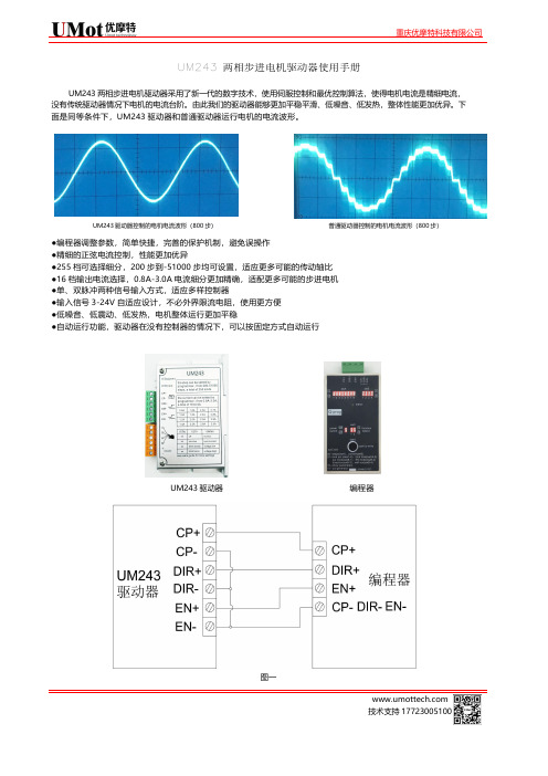
UM243两相步进电机驱动器使用手册UM243两相步进电机驱动器采用了新一代的数字技术,使用伺服控制和最优控制算法,使得电机电流是精细电流,没有传统驱动器情况下电机的电流台阶。
由此我们的驱动器能够更加平稳平滑、低噪音、低发热,整体性能更加优异。
下面是同等条件下,UM243驱动器和普通驱动器运行电机的电流波形。
UM243驱动器控制的电机电流波形(800步)普通驱动器控制的电机电流波形(800步)●编程器调整参数,简单快捷,完善的保护机制,避免误操作●精细的正弦电流控制,性能更加优异●255档可选择细分,200步到-51000步均可设置,适应更多可能的传动轴比●16档输出电流选择,0.8A-3.0A 电流细分更加精确,适配更多可能的步进电机●单、双脉冲两种信号输入方式,适应多样控制器●输入信号3-24V 自适应设计,不必外界限流电阻,使用更方便●低噪音、低震动、低发热,电机整体运行更加平稳●自动运行功能,驱动器在没有控制器的情况下,可以按固定方式自动运行UM243驱动器编程器图一 电流和细分设置参数设置前,请按照图一连接驱动器和编程器,并通电。
①拨swC=00;②swA 设置步数,swB 设置电流细分,参照下面表1和表2设置;③点击start 按键,若绿灯闪动数次,最后一次闪动红灯,则设置成功;注意:如果下一台驱动器步数和电流设置不变,则只需进行上面的第③步即可,整个过程简单、快捷、方便。
表1步数设置(swA 设置) sw1电流(A )sw2电流(A )sw3电流(A )sw4电流(A )00000.80100 1.61000 2.31100 2.70001 1.00101 1.81001 2.41101 2.80010 1.20110 2.01010 2.51110 2.900111.401112.210112.611113.0其他参数设置除了电流和步数以外,如果对驱动器UM243有特殊场合使用要求,则可以更改以下参数,满足不同要求。
Q 系列二相 三相步进电机驱动器使用手册(二相 三相)说明书

Q 系列二相/三相步进电机驱动器,为全新一代全数字步进驱动器,它采用了当前较新的数字技术,使用伺服控制理论及最优控制电流台阶,所以步进电机能达到:更优异的性能、更优异的平稳性、低速静音效果、极低的发热量,下图是Q 系列驱动器和细分驱动Q 系列驱动器使用手册(二相/三相)算法,它没有传统驱动器的【拍数】和【细分】概念,无论设定步数是多少,电机电流都是精细的正弦电流,而不会有细分概念下的器在相同条件下实测的电机电流波形,本图为示波器实拍图,未做任何加工处理。
Q 系列驱动器控制的电机电流波形(800步) 细分型驱动器控制的电机电流波形(800步)精细的正弦电流控制以达到优异的性能 优异的平稳性、低速静音效果、极低的发热量 多达255档的步数选择,可方便适应不同传动轴比 输入信号幅值为3-24V 自适应设计,不必外接限流电阻 单、双脉冲二种信号方式 关机时自动断点记忆 电机转向可以设定 方便灵活的设定和读出方式 16 档输出电流选择 自动运行功能 11 档锁定电流百分比选择(0-100%) 完善的自检测能力 16 档锁定时间选择(0.1-2秒) 完善的保护机制 使能端(EN 端)可以设定为脱机模式或锁定模式 特别适用于机器人和3D 打印机等高档应用场合【Q 系列驱动器一览表(二相)】(注:所有型号的驱动器都具有255档步数可供选择,范围:200-51000步)(接上表)【Q系列驱动器一览表(三相)】(注:所有型号的驱动器都具有255档步数可供选择,范围:200-51000步) 完全相同,但体积减小便于安装、信号连接方便、有更好的性价比。
此驱动器和本公司切割机控制系统完美结合,驱动器无拨码开关,其参数在系统内设定,驱动器的运行状态被系统时时监测且用于控制。
输入电源:AC(40-70)V,输出电流:2.2-6.0A,机身尺寸:192×120×56,四点安装:302×37,重量:1.0Kg。
VD2 两相步进电机驱动器 用户手册说明书

目录1 简介 (3)1.1 概述 (3)1.2 特性 (3)2 产品功能框图 (4)3 性能指标 (4)3.1 电气指标 (4)3.2 环境指标 (4)4 端口与接线 (5)4.1 电源连接 (5)4.2 电机连接 (6)4.3 控制信号连接 (7)4.3.1 脉冲&方向信号 (7)4.3.2 使能信号 (7)4.3.3 控制信号输入示例 (7)4.3.4 驱动器状态指示灯 (8)5 驱动器运行参数设定 (9)5.1 电流设定 (9)5.2 自动减流设定 (9)5.3 细分设定 (10)5.4 自检 (10)5.5 细分插补 (10)5.6 负载惯量选定 (11)5.7 数字信号滤波选定 (11)6 安装 (12)7.1 机械尺寸 (12)7.2 驱动器安装 (12)1 简介感谢您选择我司的驱动器。
希望我们产品优越的性能、优异的质量和优秀的性价比可以帮助您成功的完成运动控制项目。
如果您对我们的产品有什么建议或者需要我们的帮助,请致电************,你也可以给我们发送邮件*******************。
1.1 概述VD2系列两相步进电机驱动器是基于PID电流控制算法设计的高性价比细分型驱动器,具有优越的性能表现,高速大力矩输出,低噪音,低振动,低发热,特别适合OEM客户的大批量应用场合。
VD2驱动器可通过拨码开关选择运行电流和细分,有16种细分,8种电流供选择,具有过压,欠压,相电流过流保护,其输入输出控制信号均采用光电隔离。
1.2 特性■供电电源 VD2:12 - 48 VDC■输出电流拨码开关设定,8种选择,最大2.2安培(峰值)■电流控制 PID电流控制算法,高速大力矩输出,低振动,低噪音,低发热■细分设置拨码开关设定,16种选择: 200, 400, 800, 1600, 3200, 6400, 12800, 25600,1000, 2000, 4000, 5000, 8000, 10000, 20000, 25000 step/rev■速度范围选配合适的步进电机,最高可达3000rpm■共振抑制自动计算共振点,抑制中频振动■系统自测驱动器上电初始化自动检测电机参数并由此优化电机电流算法和抗共振电子阻尼系数■控制方式脉冲&方向模式,双脉冲模式■输入滤波拨码开关选择,2MHZ/150KHz数字信号滤波器■空闲电流拨码开关选择在电机停止运行后1.0秒电流会自动减为运行电流的50%或90%■产品自检拨码开关启停,电机以1rev/s速度做正反转两圈往复运动■负载惯量拨码开关选择高低不同的负载惯量,使系统运行在最佳状态■细分插补拨码开关选定,可降低电机运转的振动,提高运行的平滑性2 产品功能框图3 性能指标3.1 电气指标驱动器参数最小值典型值最大值单位供电电压12-48VDC 输出电流(峰值)0.3- 2.2Amps控制信号导通电流61015mA步进脉冲频率2-2M Hz步进脉冲宽度250--ns方向信号宽度50--us欠压保护点-10-VDC过压保护点-52-VDC输入信号电压 4.0-28VDC驱动器初始化时间-- 2.5S 3.2 环境指标冷却方式自然冷却或强制冷却使用环境使用场合避免粉尘,油雾及腐蚀性气体工作环境温度0-40°C [32 - 104°F]最高环境湿度90% RH(无结露)存储温度-10-70°C [14 - 158°F]振动 5.9m/s2 maxBlock DiagramVD24 端口与接线请参照接口关系图,使用VD2驱动器,需要做以下准备:12-48VDC 合适功率的直流电源控制信号源相匹配的步进电机(为取得最佳性能,请与英国AML 的真空步进电机相匹配)4.1 电源连接如果您的电源输出端没有保险丝或一些别的限制短路电流的装置,可在电源和驱动器之间放置一个适当规格的快速熔断保险丝(规格不得超过3Amps)以保护驱动器和电源,请将该保险丝串联于电源的正极和驱动器的V+之间。
- 1、下载文档前请自行甄别文档内容的完整性,平台不提供额外的编辑、内容补充、找答案等附加服务。
- 2、"仅部分预览"的文档,不可在线预览部分如存在完整性等问题,可反馈申请退款(可完整预览的文档不适用该条件!)。
- 3、如文档侵犯您的权益,请联系客服反馈,我们会尽快为您处理(人工客服工作时间:9:00-18:30)。
运动系统控制产品使用手册上海昀研自动化科技有限公司二〇〇九年七月第三版两相步进电机返回目录■ 20mmHB系列两相步进电机◆步距角(Step Angle) 1.8°◆步距精度(Step Accuracy) ±5%◆温升(Temperature Rise) 75℃Max◆环境温度(Ambient Temperature Range) -20℃~+50℃◆绝缘等级(Insulation Class) B◆绝缘电阻(Insulation Resistance) 500VDC100MΩMin◆绝缘强度(Dielectric Strength) 500VAC50Hz1Ma Minute◆径向跳动(radial runout) 0.02mmMax(450g 负载)◆轴向间隙(axial clearance) 0.08mmMax(450g 负载)技术参数(Specifications)型号Model步距角Step Angle(O)机身长LengthL(mm)额定电流Current(A/phase)相电阻Resistance(Ω/phase)相电感Inductance(mH/phase)保持转矩Holding torque(N.m)转动惯量Rotor inertia(kg.cm2)重量Weight(kg)20HB30-064 1.8 30 0.6 6.5 1.7 0.018 2 0.06 20HB33-064 1.8 33 0.6 6.5 1.7 0.018 2 0.06 20HB42-084 1.8 42 0.8 5.4 1.5 0.03 3 0.08 ▲以上仅为代表性产品,可按要求另行制作。
外形尺寸(Dimension)接线图(Connections)力矩测试数据(仅供参考)电机型号20HB30-064、20HB33-064、20HB42-084 配套驱动器型号YK2204MA测试条件驱动电压: DC28V 驱动器设为400步/转转速转/分30 60 90 120 180 240 300 360 400 20HB30-064 0.014N.m 0.014N.m 0.014N.m 0.013N.m 0.0125N.m 0.012N.m 0.013N.m 0.012N.m 0.010N.m 20HB33-064 0.014N.m 0.014N.m 0.014N.m 0.013N.m 0.0125N.m 0.012N.m 0.013N.m 0.012N.m 0.010N.m 20HB42-084 0.025N.m 0.027N.m 0.027N.m 0.027N.m 0.027N.m 0.026N.m 0.025N.m 0.023N.m 0.020N.m◆电机特性数据和技术数据都是在匹配我公司驱动器驱动的情况下测得,测试电压为28VDC。
◆电机安装时务必用电机前端盖安装止口定位,并注意公差配合,严格保证电机轴与负载轴的同心度。
◆电机与驱动器连接时,请勿接错相。
两相步进电机返回目录■ 28mmHB系列两相步进电机◆步距角(Step Angle) 1.8°◆步距精度(Step Accuracy) ±5%◆温升(Temperature Rise) 75℃Max◆环境温度(Ambient Temperature Range) -20℃~+50℃◆绝缘等级(Insulation Class) B◆绝缘电阻(Insulation Resistance) 500VDC100MΩMin◆绝缘强度(Dielectric Strength) 500VAC50Hz1Ma Minute◆径向跳动(radial runout) 0.02mmMax(450g 负载)◆轴向间隙(axial clearance) 0.08mmMax(450g 负载) 技术参数(Specifications)型号Model步距角Step Angle(O)机身长LengthL(mm)额定电流Current(A/phase)相电阻Resistance(Ω/phase)相电感Inductance(mH/phase)保持转矩Holding torque(N.m)转动惯量Rotor inertia(g.cm2)重量Weight(kg)28HB28-064 1.8 28 0.60 4.2 2.2 0.03 6 0.10 28HB28-034 1.8 28 0.35 12 5.8 0.03 6 0.10 28HB32-064 1.8 32 0.67 5.6 3.4 0.06 9 0.11 28HB32-096 1.8 32 0.95 2.8 0.8 0.043 9 0.11 28HB45-064 1.8 45 0.67 6.8 4.9 0.095 12 0.40 28HB45-096 1.8 45 0.95 3.4 1.2 0.075 12 0.40 28HB51-064 1.8 51 0.67 9.2 7.2 0.12 18 1.20 28HB51-096 1.8 51 0.95 4.6 1.8 0.09 18 1.20 ▲以上仅为代表性产品,可按要求另行制作。
外形尺寸(Dimension)接线图(Connections)力矩测试数据(仅供参考)电机型号28HB32-096、28HB45-096、28HB51-096 配套驱动器型号YK2304MA测试条件驱动电压: DC28V 驱动器设为400步/转转速转/分30 60 90 120 180 240 300 360 400 28HB32-096 0.039N.m 0.035N.m 0.035N.m 0.032N.m 0.03N.m 0.03N.m 0.027N.m 0.027N.m 0.024N.m 28HB45-096 0.075N.m 0.075N.m 0.070N.m 0.068N.m 0.062N.m 0.06N.m 0.055N.m 0.05N.m 0.040N.m 28HB51-096 0.083N.m 0.075N.m 0.073N.m 0.071N.m 0.70N.m 0.06N.m 0.055N.m 0.05N.m 0.048N.m◆电机特性数据和技术数据都是在匹配我公司驱动器驱动的情况下测得,测试电压为28VDC。
◆电机安装时务必用电机前端盖安装止口定位,并注意公差配合,严格保证电机轴与负载轴的同心度。
◆电机与驱动器连接时,请勿接错相。
■ 35mmHB系列两相步进电机◆步距角(Step Angle) 1.8°◆步距精度(Step Accuracy) ±5%◆温升(Temperature Rise) 75℃Max◆环境温度(Ambient Temperature Range) -20℃~+50℃◆绝缘等级(Insulation Class) B◆绝缘电阻(Insulation Resistance) 500VDC100MΩMin◆绝缘强度(Dielectric Strength) 500VAC50Hz1Ma Minute◆径向跳动(radial runout) 0.02mmMax(450g 负载)◆轴向间隙(axial clearance) 0.08mmMax(450g 负载) 技术参数(Specifications)型号Model步距角Step Angle(O)机身长LengthL(mm)额定电流Current(A/phase)相电阻Resistance(Ω/phase)相电感Inductance(mH/phase)保持转矩Holding torque(N.m)转动惯量Rotor inertia(g.cm2)重量Weight(kg)35HB20-046 1.8 20 0.45 25.0 9.0 0.05 8 0.10 35HB20-074 1.8 20 0.73 9.0 4.0 0.06 8 0.10 35HB26-076 1.8 26 0.76 9.0 4.8 0.08 10 0.13 35HB26-074 1.8 26 0.75 4.3 4.0 0.07 10 0.13 35HB28-046 1.8 28 0.40 26.0 10.0 0.1 11 0.14 35HB28-054 1.8 28 0.54 13.0 9.5 0.08 11 0.14 35HB34-056 1.8 34 0.50 22.0 12.0 0.1 13 0.17 ▲以上仅为代表性产品,可按要求另行制作。
外形尺寸(Dimension)接线图(Connections)力矩测试数据(仅供参考)电机型号35HB34-056、35HB26-076、35HB28-046、35HB34-056 配套驱动器型号2304MA测试条件驱动电压: DC28V 驱动器设为400步/转转速转/分30 60 90 120 180 240 300 360 40035HB20-046 0.065N.m 0.063N.m 0.068N.m 0.065N.m 0.065N.m 0.059N.m 0.058N.m 0.055N.m 0.050N.m 35HB26-076 0.085N.m 0.088N.m 0.088N.m 0.085N.m 0.085N.m 0.084N.m 0.084N.m 0.084N.m 0.080N.m 35HB28-046 0.11 N.m 0.11N.m 0.11N.m 0.11N.m 0.1N.m 0.099N.m 0.094N.m 0.09 N.m 0.084N.m 35HB34-056 0.13 N.m 0.135N.m 0.135N.m 0.13N.m 0.122N.m 0.12N.m 0.115N.m 0.11N.m 0.10 N.m◆电机特性数据和技术数据都是在匹配我公司驱动器驱动的情况下测得,测试电压为28VDC。
◆电机安装时务必用电机前端盖安装止口定位,并注意公差配合,严格保证电机轴与负载轴的同心度。
◆电机与驱动器连接时,请勿接错相。
■ 39mmHB系列两相步进电机◆步距角(Step Angle) 1.8°◆步距精度(Step Accuracy) ±5%◆温升(Temperature Rise) 75℃Max◆环境温度(Ambient Temperature Range) -20℃~+50℃◆绝缘等级(Insulation Class) B◆绝缘电阻(Insulation Resistance) 500VDC100MΩMin◆绝缘强度(Dielectric Strength) 500VAC50Hz1Ma Minute◆径向跳动(radial runout) 0.02mmMax(450g 负载)◆轴向间隙(axial clearance) 0.08mmMax(450g 负载) 技术参数(Specifications)型号Model步距角Step Angle(O)机身长LengthL(mm)额定电流Current(A/phase)相电阻Resistance(Ω/phase)相电感Inductance(mH/phase)保持转矩Holding torque(N.m)转动惯量Rotor inertia(g.cm2)重量Weight(kg)39HB20-054 1.8 20 0.48 25 22 0.1 11 0.12 39HB20-044 1.8 20 0.40 6.8 6.5 0.055 11 0.12 39HB26-046 1.8 26 0.42 15 8.5 0.08 13 0.14 39HB31-056 1.8 31 0.50 9 3.5 0.1 18 0.16 39HB34-044 1.8 34 0.40 30 42 0.21 20 0.18 39HB34-104 1.8 34 1.00 5 3 0.18 20 0.18 ▲以上仅为代表性产品,可按要求另行制作。