方太cxw228-JQo1T说明书
cxw-200烟机说明书

CXW-200系列油烟机产品说明卡CXW-200系列产品特点:1.本机进风口采用防漏油专用结构,内腔采用外翻式专利结构,整体拉伸成形。
2.风机系统的叶轮采用特殊涂层处理,易擦洗。
3.该吸油烟机采用不锈钢网孔专利结构,有效过滤分离油烟,进风更顺畅。
4.整体静音优化系统,配置优质轴承,静音电机,确保整机运行平稳宁静。
5.照明采用高效节能LED灯。
装箱清单请您打箱后逐一检查以下产品和附件是否齐全,如有缺少或损坏请与CXW-200系列产品的安装注意事项:1.安装墙壁应能承受油烟机重量,否则禁止安装;2.墙壁打孔时应避开埋设的电线,以免发生触电危险;3.友情提示您,尽量选择专业人员安装,由于自行安装不当导致的适用问题及事故责任保险公司不负赔偿责任。
安装尺寸如图所示:日常维护及注意事项1.如不按说明书规定的方法清洗,吸油烟机有起火的危险;2.如电源线损坏,须由公司指定专用软线更换;3.吸油烟机在炉火消耗煤气或其它燃料时使用,房间必须通风良好;4.禁止炉火直接烘烤吸油烟机5.本机系家用电器,避免在特殊环境中使用;6.要经常清除吸油烟机上的油污。
擦拭吸油烟机时,务必拔掉电源插头,并带上橡胶手套,以防止钢板棱边划伤手指;7.面板清洗建议每日使用结束后用洗洁精水轻擦油污,防止积重难于打理;8.油网清洗建议每半个月用软布蘸洗洁精轻擦干净,清洗周期视使用情况可适当延长或缩短;9.清洗前,需等待油杯冷却,方可清洗,防止烫伤;10.清洗时应选用中性洗涤剂,禁用含研磨剂的洗涤液及易燃清洁剂,去污后用清水洗掉洗涤剂并擦干;11.严禁用水冲洗,防止电器部件进水;12.清洗时,禁用锋利、硬物和钢丝球等伤害表面的器具;13.特别注意,使用动物油脂易导致油孔堵塞,应经常疏通;14.本类产品连续使用不应超过3小时,否则会影响使用寿命。
环境与保护1.外包装材料是可回收材料,内包装泡沫塑料为不可降解材料,请分类处理,或者与您附近的回收中心联系。
franke cxw220t15抽油烟机说明书
franke cxw220t15抽油烟机说明书
1、首先油烟机电源插座必须使用有可靠地线的专用插座,置于原因相信已经不用多说了,家电产品的用电安全才是第一位的。
2、为了保证排烟效果和使用安全,在安装时油烟机的安装高度应不低于650mm,尽可能安装在炉灶正上方。
为了获得良好的排烟效果,最好在烹饪前开启吸油烟机1-2分钟。
3、在更换油烟机灯泡时,功率不要超过说明书上标示的最大值,否则容易导致连接灯座的电线和灯座的温升过高,加速电线绝缘层的老化,造成触电的潜在危险,甚至导致火灾。
方太说明书
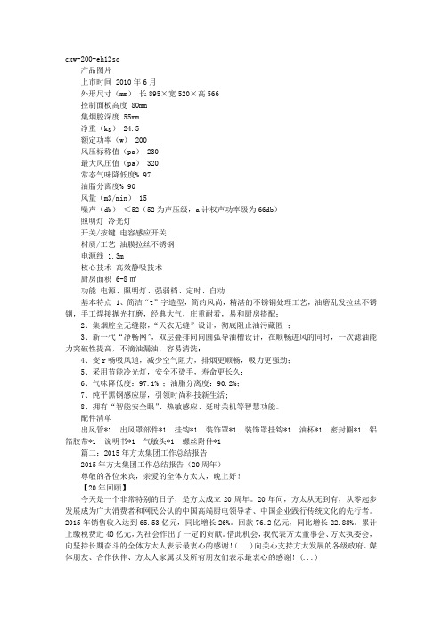
cxw-200-eh12sq 产品图片上市时间 2010年6月外形尺寸(mm)长895×宽520×高566 控制面板高度 80mm集烟腔深度 55mm净重(kg) 24.5额定功率(w) 200风压标称值(pa) 230最大风压值(pa) 320常态气味降低度% 97油脂分离度% 90风量(m3/min) 15噪声(db)≤52(52为声压级,a计权声功率级为66db)照明灯冷光灯开关/按键电容感应开关材质/工艺油膜拉丝不锈钢电源线 1.3m核心技术高效静吸技术厨房面积 6-8㎡功能电源、照明灯、强弱档、定时、自动基本特点 1、简洁“t”字造型,简约风尚,精湛的不锈钢处理工艺,油磨乱发拉丝不锈钢,手工焊接抛光打磨,经典大气,庄重耐看,易和厨房搭配;2、集烟腔全无缝隙,“天衣无缝”设计,彻底阻止油污藏匿;3、新一代“净畅网”,双层叠排同向圆弧导油槽设计,在顺畅进风的同时,一次滤油能力突破性提高,不滴油漏油,容易清洗;4、变r畅吸风道,减少空气阻力,排烟更顺畅,吸力更强劲;5、采用节能冷光灯,安全不烫手,寿命更长久;6、气味降低度:97.1% ;油脂分离度:90.2%;7、纯平黑钢感应屏,引领时尚科技新生活;8、拥有“智能安全眼”、热敏感应、延时关机等智慧功能。
配件清单出风管*1 出风罩部件*1 挂钩*1 装饰罩*1 装饰罩挂钩*1 油杯*1 密封圈*1 铝箔胶带*1 说明书*1 气敏头*1 螺丝附件*1 篇二:2015年方太集团工作总结报告2015年方太集团工作总结报告(20周年)尊敬的各位来宾,亲爱的全体方太人,晚上好!【20年回顾】今天是一个非常特别的日子,是方太成立20周年。
20年间,方太从无到有,从零起步发展成为广大消费者和网民公认的中国高端厨电领导者、中国企业践行传统文化的先行者。
2015年销售收入达到65.53亿元,同比增长26%。
回款76.2亿元,同比增长22.88%。
豪华油烟机使用说明书中英对照

豪华吸油烟机Luxurious Cooker Hood安装说明Installation Instruction1、安装工具准备,①冲击电钻(带钻头)②扳手③螺丝刀④尺1. Prepare installation tools: ①Impact Electric Drill (with drill) ②Spanner ③Screwdriver ④Ruler2、确定位置:吸油烟机平行安装于炉头正上方.底部距炉台安装参考高度650—750mm,可拆卸挡板安装参考尺寸430mm,可根据实际的安装情况适当调整。
安装孔距机体应垂直居中和保持水平。
(如煤气炉灶安装说明规定了较大的安装距离者,对此应予考虑,)例:吊顶装饰罩(无拆卸挡板的安装方法)吊顶装饰罩可拆卸挡板(有拆卸挡板的安装方法)2. Determine Installation Site: the hood should be installed over the cooker. The reference setting distance from the bottom to the cooker is 650-750mm. The reference dimension of the dischargeable baffle plate is 430mm. It can be adjusted according to practical installation situation. The mounting hole should align vertical centers and keep horizontal with the cooker hood.(For instance, if a longer distance is stipulated in the instruction manual of cooker, it should be considered.)E.g. suspending ceiling decorative covering (installation method without dischargeable baffle plate )Suspending ceiling decorative covering dischargeable baffle plate (installation method with dischargeable baffle plate )3、安装挂脚:按照挂脚的尺寸在墙壁的相应位置上.钻出直径为8mm (严禁钻孔过大,造成膨胀管松动而意外跌落).深度为50一60mm的四个孔,将膨胀管压入孔内.再用随机配备的St4X40木螺钉将挂脚可靠固定。
方太水槽洗碗机 SD2F-P1X SD2F-P1XL 使用说明书

1CONTENTS Safety Instructions 2Installation Requirements 3Installation List 5Product Packing List5Auxiliary Materials for Installation 6Installation Tools 7Installation778Product Dimensions Installation StepsDear Client,Thank you for choosing the FOTILE sink dishwasher products manufactured by FOTILE. Please read the installation instructions carefully before installation. Please call the FOTILE Service hotline for any needs at 1-888-315-0366.To avoid injury and property damage to users and other persons, please read and observe all safety instructions and warnings.1. The personnel installing this product must have basic mechanical, electrical and plumbing skills.This product must be installed by certified professional plumbers.2. It is the responsibility of the installer for correct installation, any product fault caused by improperinstallation will not be covered by the FOTILE warranty.3. Disconnect the power before installing the product to prevent electric shock.4. Do not wet the power cable, power plug, connectors or other electric parts, or it may cause electricshock or other accidental damages.5. Do not modify, stretch, knot the power cable or place heavy objects on it. Doing so may causedamage to the power cable and result in electric shock, fire, etc.6. Do not touch the power cable or electrical parts with wet hands, or it may cause electric shock.7. The Sink Dishwasher must be connected to a grounded electrical outlet. If you don’t have agrounded electrical outlet, please have a certified electrician install one. Failure to do so can result in electrical shock and injury.8. If the power cable is damaged, it must be replaced by Fotile Service Technicians to avoid danger.9. During installation, please pay attention to the edges and corners of the sink to avoid scratches.10. Only cold water can be supplied to the water inlet of the Fotile sink dishwasher. Supplying hotwater will affect the produce cleaning function for fruits and vegetables. The FOTILE Sink Dish-washer uses its’ own heating element to heat water for dishwashing.11. Do not allow children to play with the plastic film or other packaging components which maycause asphyxiation and possible death.12. The countertop which the product is installed into must have sufficient strength to support 220Ibs (100Kg). Please follow all mounting directions to be firmly installed into the countertop correctly.13. The countertop which this product is installed into, must be made from temperature and humidityresistant materials.14. During product installation, the functional sink must maintain a distance of 11 13/16 "(300mm) ormore from the gas meter and the gas pipeline. The junction box must be a distance of 5 15/16"(150mm) or more from the gas meter and gas pipeline.15. Please adhere to all local laws and regulations for the connection of the drain hose.16. Please save this Installation Manual for future reference.1. Objects obstructing the functional sink and drain line such as a gas line or gas meter should notbe installed in the cupboard;2. The water supply and power socket should be arranged in the cupboard (or the adjacentcupboard).3. The 240V/60Hz power supply shall be provided. A wire with a diameter of more than 16AWG (1.5mm2) should be used and reliably grounded.4. The pressure of the installation waterway should meet the requirements of 20.3 psi-145.04 psi.5. Height requirements for drain hose: The height from the top of the installed countertop to the drainhose should be greater than or equal to 21 11/16 "(550mm).To avoid injury and property damage to users and other persons, please read and observe all safety instructions and warnings.Net Distance from Gas Hose Hose and equipmentElectricalequipmentParallel Lying9 7/8”(250mm)39 3/8”(1,000mm)11 13/16”(300mm)5 15/16”(150mm)Exposed insulated wire or cableExposed wire with voltage less than 1,000VSwitchboard or distribution box, electricity meterElectrical socket, power switchCross Lying3 15/16”(100mm)39 3/8”(1,000mm)Not allowedNot allowed6. Opening size of the countertop and size requirements in the cupboardOpening size of the countertopt Inner wall size of cupboardLength Length Length Length Length Length38”18 1/8”7/16”≥38 1/4”≥20 1/8”≥35 7/16”GroundMesa≥2111/16"(55mm)GroundMesa≥2111/16"(55mm)7. After the dishwasher is installed, the whole machine can be taken out from the countertop forfuture maintenance.8. There should be at least an 18” space above the countertop so that the door of the dishwashercan be opened normally.■ Installation ListProduct Packing Box List1111111111111 Operation & Maintenance ManualInstallation Guide ManualWarranty CardFiltration assemblySpray armConnecting tube of the overflowseat- exhaust teeClampRubber tubeElectrical lock teeExhaust teeSewer hose assembly forfunctional sinkDish rackVegetable basketRecommended installation tools(please use appropriate tools according to actual installation environment)Recommended installation accessories (purchase by oneself) √: Must ×: No need ○: OptionalIII. Installation■ Product dimensions39"(990mm)21 5/16"(541m m )8 11/16"(219m m )8 15/16"(226m m )37 3/8"(948mm)10"(253mm)18 15/16"(480m m )19 5/16"(490mm)(16 3/8"(415m m )1 3/8"(34mm)5 7/8"(148m m )21"(533mm)25 7/8"(657mm)Φ1 1/16"(Ø26m m )1 9/16"(39mm)4ft 3-prong ground-type power supply cord17 3/4"(450mm)7 1/16"(178mm)2 13/16"(71mm)15 15/16"(404mm)13 1/8"(332m m )Installation stepsStep 1: Unpack the unit. Take out the dishwasher from the carton and place it on a temporary level and sturdy surfaceStep 2: Install water inletConnect the inlet hose with 3/8” interface to the joint of the water inlet valve and screw it together.Step 3: Install accessories1. Take out the rubber hose from the packaging bag and insert one end of the rubber hoseinto the drip hole under the electrical lock.2. Put the clamp into the upper end of the electrical lock tee, insert the electrical lock tee intothe drop opening of the overflow seat for the functional sink, and lock the clamp.3. Insert the other end of the rubber hose into the electrical lock tee.4. Put the clamp into the upper end of the overflow base - exhaust tee, insert the joint pipe of overflow seat and insert the exhaust tee into the drip hole of the overflow base for the sink, then put the overflow base into the exhaust tee, and lock the clamp.5. Put the clamp into one end of the exhaust pipe, insert into the side hole of the exhausttee, and lock the clamp.6. Connect and pre-tighten the drain hose assembly for the functional sink and the drainopening of the functional sink. Ensure there is a gasket at the joint.7. Put the clamp into the two overflow pipes, insert the shorter one into the drainage openingof electrical lock tee for the functional sink, insert the longer one into the drainage opening of the overflow seat - exhaust tee, and lock the clamp.Step 4: Install the faucet and tee1. Install the faucet and fasten it.2. Collect the tee at the angle valve of cold water.Step 5: Clean and glue the countertop1. Clean and install the countertop2. Spray glass cement along the perimeter ofthe mounting hole edges and ensure there isa plenty and continuous supply.Step 6: Place the sink dishwasher1. Wear protective gloves and place the sink dishwasher into the opening.Note: Do not lift or move the sink dishwasher by the faucet as this will cause damage and possible water leakage.Step 7: Connect water pipes1. Correctly connect the cold and hot water pipes of the faucet.2. Connect the water inlet of the sink dishwasher and cold water valve tee, and screw itdown.Note: Only cold water can be supplied to the water inlet of the dishwasher.3. Open the angle valve and ensure there is no leakage at each joint.Step 8: Connect power supply1. Cut off power supply of the electrical box2. Connect the power cable of the sink dishwasher and the cable in the electrical box, andtake the necessary insulation protection measuresNote: The null line and live wire MUST be connected correctly and have a reliable ground.Power wireGreen wire to greenwire (ground wire)Black wire toblack wireRed wire tored wire Junction box Power wireStep 9: Install the drainer or waste disposerDrainer:1. Correctly install the drainer, connect with the drain hose of the sink dishwasher andensure tightness and no leakage.Note:If the pipeline needs to be shortened, cut C end, cutting length ≤2".If the pipeline needs to be lengthened, unscrew the thread of D end and pull it out, pull-out distance ≤1".Kitchen Sink Disposal1. Correctly install the kitchen Sink Disposal and ensure it’s is installed in place, without leakage.2. Adjust the water outlet of the kitchen Sink Disposal and tightly connect it with the drain hose of the sink dishwasher, without leakage. Note:If the pipeline needs to be shortened, cut C end (≤2”).If the pipeline needs to be lengthened, unscrew the thread of the D end and pull it out, pull-out distance ≤1”.Step 10: Check the pipeline1. Check whether the pipeline connected with the sink has leakage.2. Check whether the pipeline connected with the functional sink has leakage.Switch on the power supply, Press the open key to open the door and take out all articlesin the sink.Press the strength key for a long time to close the valve under the standby (black screen) mode, fill the overflow opening with water, and check the functional sink and the drain hosefor leaks.Press the water level key for a long time to open the valve and drain water, and check each joint of the drain hose for leaks.Step 11: Final Steps1. Spray glass cement along the product edge.2. Place the filter plate assembly togetherEnsure the drain hose keeps vertical or horizontal state Ensure the drain hose keeps vertical or horizontal state(Other pipelines of air gap can be connected at A. If there is no such requirement, please seal it or directly use the pipeline without A interface)(Air Gap or other pipelines can be connected atB. If there is no such requirement, please seal it)3. Install the spray arm: Pinch the gray locking tab under the spray arm, place it to theposition shown in the picture and rotate clockwise. After hearing “click” sound, Spin the spray arm and ensure smooth rotation.4. Installation CompleteEstimado cliente,Gracias por elegir los productos para lavaplatos fregadero FOTILE fabricados por FOTILE. Lea atentamente las instrucciones de instalación antes de realizar la instalación. Para cualquier consulta, llame a la línea directa de servicio FOTILE al 1-888-315-0366.1 ContenidoInstrucciones de seguridad2 Requisitos de instalación3 Lista de instalación5 Lista de empaque del producto5 Materiales auxiliares para la instalación6 Herramientas de instalación7 Instalación778 Dimensiones del productoPasos de instalaciónPara evitar lesiones y daños a la propiedad de los usuarios y otras personas, lea y siga todas las instrucciones y advertencias de seguridad.1. El personal que instale este producto debe tener conocimientos básicos de mecánica, electrici-dad y fontanería. Este producto debe ser instalado por fontaneros profesionales certificados. 2. El instalador es responsable de realizar la instalación correcta, cualquier avería del productoprovocada por una instalación incorrecta no está cubierta por la garantía de FOTILE.3. Desconecte la corriente antes de instalar el producto para evitar descargas eléctricas.4. No moje el cable de alimentación, el enchufe, los conectores u otras piezas eléctricas, ya quepuede provocar una descarga eléctrica u otros daños.5. No modifique, estire o anude el cable de alimentación ni coloque objetos pesados sobre él. De locontrario, puede dañar el cable de alimentación y provocar una descarga eléctrica, incendio, etc.6. No toque el cable de alimentación ni las piezas eléctricas con las manos mojadas ya que podríaprovocar una descarga eléctrica.7. El lavaplatos fregadero debe estar conectado a una toma de corriente con conexión a tierra. Sino tiene una toma de corriente con conexión a tierra, solicite a un electricista certificado que le instale una. De lo contrario podría provocar descargas eléctricas y lesiones.8. Si el cable de alimentación está dañado, los técnicos de servicio de Fotile deben reemplazarlopara evitar peligros.9. Durante la instalación, preste atención a los bordes y esquinas del fregadero para evitararañazos.10. Solo se puede suministrar agua fría a la entrada de agua del lavaplatos fregadero Fotile. Elsuministro de agua caliente afectaría a la función de limpieza de frutas y verduras. El lavaplatos fregadero FOTILE utiliza su propio elemento calefactor para calentar el agua y lavar la vajilla. 11. No permita que los niños jueguen con la película de plástico u otros componentes del embalajeque podrían provocar asfixia o incluso la muerte.12. La encimera en la que se instala el producto debe tener la resistencia suficiente para soportar220 Ibs (100Kg). Siga todas las instrucciones de montaje para instalarlo firmemente en la encimera correctamente.13. La encimera en la que se instale el producto debe ser de materiales resistentes a la temperaturay la humedad.14. Durante la instalación del producto, el fregadero funcional debe mantener una distancia de 1113/16" (300 mm) o más del medidor de gas y la tubería de gas. La caja de conexiones debe estar a una distancia de 5 15/16" (150 mm) o más del medidor de gas y la tubería de gas.15. Cumpla con todas las leyes y regulaciones locales para realizar la conexión de la manguera dedrenaje.16. Guarde este manual de instalación para futuras consultas.1. No debe instalar en el armario objetos que obstruyan el fregadero y la línea de drenaje, como unalínea de gas o un medidor de gas;2. El suministro de agua y el enchufe de alimentación se deben colocar en el armario (o en el arma-rio adyacente).3. Se debe proporcionar una fuente de alimentación de 240V/60Hz. Se debe utilizar un cable conun diámetro de más de 16AWG (1,5 mm2) y una conexión fiable a tierra.4. La presión de instalación de la vía de agua debe cumplir con los requisitos de 20,3 psi-145,04 psi.5. Requisitos de altura de la manguera de desagüe: la altura desde la parte superior de la encimerahasta la manguera de desagüe debe ser mayor o igual a 21 11/16"(550mm).Para evitar lesiones y daños materiales a los usuarios y otras personas, lea y observe todas las instrucciones y advertencias de seguridad.6. Tamaño de la abertura de la encimera y requisitos de tamaño en el armarioT amaño de la abertura de la encimera T amaño de la pared interior del armarioLargo AnchoÁngulo R Largo Ancho Alto38”18 1/8”7/16”≥38 1/4”≥20 1/8”≥35 7/16”Distancia neta desde la manguera de gasManguera y equipoEquipoeléctricoParalela9 7/8”(250mm)39 3/8”(1,000mm)11 13/16”(300mm)5 15/16”(150mm)Alambre o cable aislado expuestoAlambre expuesto con voltaje inferior a 1,000VAlambre o cable aislado expuestoCruzada3 15/16”(100mm)39 3/8”(1,000mm)No permitidoNo permitido Cuadro de distribución o tablero de distribu-ción, medidor de electricidadGroundMesa≥2111/16"(55mm)GroundMesa≥2111/16"(55mm)7. Una vez instalado el lavaplatos, se puede extraer toda la máquina de la encimera para su man-tenimiento en el futuro.8. Debe haber un espacio mínimo de 18” por encima de la encimera para poder abrir bien la puerta del lavaplatos. (Consulte la ilustración en la Sección III) ■ Lista de InstalaciónLista de Caja de Embalaje del Producto111111 set1115111 set Manual de Operación y MantenimientoGuía de InstalaciónTarjeta de garantíaConjunto de filtraciónBrazo rociadorTubo de conexión deldesbordamiento asiento- tubode escapeAbrazaderaTubo de gomaT de cierre eléctricoT de escapeConjunto de manguera dedesagüe para fregadero funcionalEstante de rejillaCesta vegetal (Herramientas de instalación recomendadas(utilice herramientas adecuadas de acuerdo con el entorno de instalación real)Accesorios recomendados de instalación (no incluidos) √: Necesario ×: No necesario ○: opcionalIII. Instalación■ Dimensiones del producto39"(990mm)21 5/16"(541m m )8 11/16"(219m m )8 15/16"(226m m )37 3/8"(948mm)10"(253mm)18 15/16"(480m m )19 5/16"(490mm)(16 3/8"(415m m )1 3/8"(34mm)5 7/8"(148m m )21"(533mm)25 7/8"(657mm)Φ1 1/16"(Ø26m m )1 9/16"(39mm)4ft 3-prong ground-type power supply cord17 3/4"(450mm)7 1/16"(178mm)2 13/16"(71mm)15 15/16"(404mm)13 1/8"(332m m )Pasos de instalaciónPaso 1: Desempaquete la unidad. Saque el lavaplatos de la caja y colóquelo en una superficie nivelada y resistente.Paso 2: Instale la entrada de aguaConecte la manguera de entrada con una interfaz de 3/8” a la junta de la válvula de entrada de agua y atorníllela.Paso 3: Instale los accesorios1. Extraiga la manguera de goma de la bolsa de embalaje e inserte un extremo de lamanguera de goma en el orificio de goteo debajo de la T de cierre eléctrico.2. Coloque la abrazadera en el extremo superior del tubo de cierre eléctrico, inserte la T decierre eléctrico en la abertura de bajada del asiento de desbordamiento para el fregadero funcional y cierre la abrazadera.3. Inserte el otro extremo de la manguera de goma en la T de cierre eléctrico.4. Coloque la abrazadera en el extremo superior de la base de desbordamiento - T de escape, inserte el tubo de unión del asiento de desbordamiento e inserte la T de escape en el orificio de goteo de la base de desbordamiento del fregadero, luego coloque la base de desbordamiento en la T de escape y cierre la abrazadera.5. Coloque la abrazadera en un extremo del tubo de escape, insértela en el orificio lateralde la T de escape y cierre la abrazadera.6. Conecte y apriete previamente el conjunto de la manguera de drenaje para el fregadero funcional y la abertura de drenaje del fregadero funcional. Asegure que haya una junta enla unión.7. Coloque la abrazadera en los dos tubos de desbordamiento, inserte el más corto en laabertura de drenaje de la T de cierre eléctrico para el fregadero funcional, inserte el más largo en la abertura de drenaje del asiento de desbordamiento - T de escape y cierre la abrazadera.Paso 4: Instale el grifo y la T1. Instale el grifo y ajústelo.2. Recoja la T en la válvula de ángulo del agua fría.Paso 5: Limpie y pegue la encimera.1. Limpie e instale la encimera.2. Pulverice cemento de vidrio por todo elperímetro de los bordes del orificio de mon-taje y garantice haya un suministro abun-dante y continuo.Paso 6: Coloque el lavaplatos del fregadero1. Utilice guantes protectores y coloque el lavaplatos del fregadero en la abertura.Nota: No levante ni mueva el lavaplatos del fregadero agarrando del grifo ya que provocará daños y posibles fugas de agua.Paso 7: Conecte las tuberías de agua1. Conecte correctamente las tuberías de agua fría y caliente del grifo.2. Conecte la entrada de agua del lavaplatos fregadero y la T de la válvula de agua fría yatornille.Nota: Solo se puede suministrar agua fría a la entrada de agua del lavavajillas.3. Abra la válvula de ángulo y asegúrese de que no haya fugas en las juntas.Paso 8: Conecte la fuente de alimentación1. Corte la fuente de alimentación del armario eléctrico2. Conecte el cable de alimentación del lavaplatos y el cable en el armario eléctrico, y sigalas medidas adecuadas de aislamiento de protección.Nota: La línea nula y el cable bajo tensión DEBEN estar conectados correctamente y tener una conexión a tierra fiable.Cable de fuenteeléctricaCable verde a cableverde (a tierra)Cable negro a cablenegro (de fuego)Cable rojo a cablerojo (de fuego) Caja de conexionesCable de fuenteeléctricaPaso 9: Instale el escurridor o triturador de desechos.Escurridor:1. Instale correctamente el escurridor, conéctelo con la manguera de desagüe del lavapla-tos y asegúrese de que quede hermético y que no haya fugas.Nota:Si precisa acortar la tubería, corte el extremo C, cortando una longitud de ≤2”.Si precisa alargar la tubería, desenrosque la rosca del extremo D y retírela, la distancia de extracción es de ≤1”.Triturador del fregadero de cocina1. Instale correctamente el fregadero de cocina y asegúrese de que esté instalado en su sitio, sin fugas.2. Ajuste la salida de agua del Triturador del Fregadero de cocina y conéctelo firmemente con la manguera de drenaje del lavaplatos del fregadero, sin fugas. Nota:Si precisa acortar la tubería, corte el extremo C (≤2”).Si precisa alargar la tubería, desenrosque la rosca del extremo D y retírela, la distancia de extracción es de ≤1”.Paso 10: Revise la tubería1. Compruebe si la tubería conectada con el fregadero tiene alguna fuga.2. Compruebe si la tubería conectada con el fregadero funcional tiene alguna fuga. Encienda la fuente de alimentación, presione la tecla de apertura para abrir la puerta ysaque todos los elementos del fregadero.Presione la tecla con fuerza durante un tiempo prolongado para cerrar la válvula en el modo de espera (pantalla negra), llene la abertura de desbordamiento con agua y compru -ebe si el fregadero y la manguera de drenaje funcionan y si hay alguna fuga.Presione la tecla de nivel de agua durante un tiempo prolongado para abrir la válvula y drenar el agua del interior, y revise si hay alguna fuga en las uniones de la manguera de drenaje.Paso 11: Pasos finales1. Pulverice cemento de vidrio por todo el borde del producto.2. Coloque el conjunto de la placa del filtroAsegúrese de que la manguera de drenaje se mantiene en estado vertical u horizontal Asegúrese de que la manguera de drenaje se mantenga en estado vertical u horizontal(Puede conectar otras tuberías de la cámara de aire en A. Si no existe este requisito, selle o use directamente la tubería sin una interfaz)(La cámara de de aire u otras tuberías sepueden conectar en B. Si no existe esterequisito, séllelo)3. Instale el brazo rociador: Apriete la pestaña de bloqueo gris debajo del brazo rociador, colóquelo en la posición que se indica en la imagen y gírelo hacia la derecha. Después de escuchar un "clic", gire el brazo rociador y asegúrese de que gira suavemente.4. Instalación completada尊敬的用户,您好!感谢您选购方太公司为您精心制造的方太水槽洗碗机产品,安装前请仔细通读本安装说明,如有任何需要敬请致电,方太服务热线 1-888-315-03661目录安全须知2安装要求3安装清单5产品包装清单5安装辅材6安装工具7安装778产品尺寸产品步骤为了避免对使用人员及其他人员造成危害及财产损害,如下均为有关安全的重要事项,敬请严格遵守,并在充分理解内容的基础上正确使用。
cxw-220-et03s产品知识与cxw-220-jd01g产品知识

1规格及附件1:规格12外部装配部件图3 外形尺寸图4 安装方法及注意事项1:安装方法①吸油烟机最低部位与炉灶表面的参考距离为670~750mm,但该距离应至少为650mm。
如果炉灶规定了较大的安装距离,则应以炉灶的规定为准。
②如安装参考图所示,在墙上钻5个深度约为60mm的Φ10孔,最上方2孔埋入2个Φ 10金属膨胀螺栓,其余3孔埋入Φ 10塑料膨胀管,用膨胀螺栓的螺母和2只Φ5木螺钉将主机挂板紧固在墙上(中间一孔暂不拧螺钉)。
③若需安装上装饰罩,请在主机挂板正上方的适当位置,钻2个Φ10孔(如安装参考图所示),分别埋入2只Φ10塑料膨胀管,用Φ5只木螺钉将上装饰罩挂板水平紧固在墙上。
④将主机挂在主机挂板上,并确保主机挂牢和平稳。
⑤如安装参考图所示,将Φ5木螺钉拧入主机挂板的中间孔,以防主机掀翻。
⑥将出风管插入出风口环槽底部,用2只ST4*10自攻螺钉将出风管固定在出风口上,并在衔接处用铝箔胶带固定密封。
⑦将出风管从预先钻好的Φ185墙孔中引出室外,室外的出口应低于室内。
若墙内排烟口径小于出风管时,可采用转接头进行转接,连接方式见右图。
注意:1. 加装转接头后,会降低吸烟排气能力。
2.安装时请将出风管充分拉展开,避免排气不畅和增加噪音,并将出风管多余部分截出。
⑧拉出上装饰罩,用2只M4*8螺钉将其紧固在上装饰罩挂板上。
⑧将油杯水平插入器具底部的油杯挂脚中,并平推到位。
⑩接通器具的电源,试运行机器,确认机器的各功能是否正常。
2:注意事项①.本器具请勿与建筑物的金属部(壁内钢丝等)接触,施工时请注意。
②.请勿将机体埋入墙内,墙壁内的钢丝有漏电场合,会流至机体。
③.使用灶具的宽度应在吸油烟机宽度之内。
④. 吸油烟机排除的气体不应排到用于排出燃烧燃气或其他燃料的烟雾使用的热烟道中。
⑤.请使用随机附件中的出风管,不可采用其他规格的出风管,否则会影响吸烟排气效果。
⑥.出风管不可拉开太长和弯曲太多,以免影响吸烟排气效果。
【精编范文】方太嵌入式烤箱说明书-范文word版 (9页)
本文部分内容来自网络整理,本司不为其真实性负责,如有异议或侵权请及时联系,本司将立即删除!== 本文为word格式,下载后可方便编辑和修改! ==方太嵌入式烤箱说明书篇一:德普嵌入式烤箱使用说明一德普8系烤箱的旋转烤叉正确使用方法如何正确时使用嵌入式烤箱里面的旋转叉,是很多消费者很关心的问题,下面对这个问题做一个详细的说明。
1、打开德普烤箱门2、将烤叉插进食物并固定好3、把烤架放置在烤箱的第二层4、把烤叉尖端放在烤箱内部预留好的专用插孔里5、倾斜放置6、将烤叉的把手放在烤架上的下弯部分7、拧开塑料把手8、为防止滴油,下方可放置一个接油盘(耐高温)或是烤盘也可9、关闭烤箱门,选择对应的烘焙模式10、按确认键启动烤箱11、如需烤叉转动,长按右边第二个菜单键/烤叉键12、功能显示屏上出现一个红色旋转标示即可13、如需停止,再次轻按菜单键/烤叉键即可1、打开德普烤箱门,将烤叉插进食物并固定好。
2、把方框型的转叉托架搁在烤箱内,从上往下第二层,带凹槽的朝外,叉子的尖端那头插到后面圆孔里,里面还有一个孔(电机孔),插到电机孔,轻轻的转动一下让杆子和孔贴合好,不能歪,否则烤叉无法转动,然后把手柄这端搁在凹槽里就可以了。
3、把手柄取下,选择任意一个烘焙模式,如需烤叉转动,长按右边第二个菜单键/烤叉键。
4、功能显示屏上出现一个红色旋转标示即可。
如需停止,再次轻按菜单键/烤叉键即可5、烤叉使用后,清理特别方便,只要用毛巾一擦即可。
温馨提示:因烤箱温度高,塑料手柄不能烘烤,等待烤叉使用完毕后,再把手柄安装到烤叉上,方便拿取,不易烫手)。
二、烤箱除味新烤箱使用之前最好先空烤一下,让各组加热管受一下热,让表面的保护涂层挥发掉,期间会有些气味和白烟出来,属于正常现象。
具体方法:◆6系(609A/B、301E、607、608等):1、最右边的功能选择钮顺时针分别用第1、第4、第7三档,温度200度左右,各空烤15分钟左右,空烤时烤箱里面放一碗自来水除味效果更好。
方太油烟机安装标准作业指导书

相关记录表
设备
工具、夹具
拟 制 审 核 会 签 标准化 批 准 页 码 第6页
油烟机预埋烟管作业指导书
文件编号
SOP-FT-2011001
版 本 A0
工序名称
防回烟装置(防烟宝)的鉴别 工序号 07 作业示意图
【图1】
【图4】
产品型号
通用版 受 控
物料明细表
NO. 物料名称(规格) 数量 单位 NO.
作业工时 2分钟
序 日期
更改内容
注意事项: 1、场景3指的是:服务工程师在和客户预约具体上门时间时,通过电话的方式向 用户了解厨房吊顶进度,以及烟管加长事宜,通过判断尽量做到预埋烟管在吊顶龙骨打好之 后,在吊顶扣板安装之前进行; 2、此工序由服务工程师电话操作。
更改者 审核者
辅助材料
相关记录表
设备
工具、夹具
版 本 A0
工序名称
吊顶空间的判断
工序号 05
作业示意图
产品型号
通用版 受 控
物料明细表
NO. 物料名称(规格) 数量 单位 NO.
物料名称
数量 单位
PCS
作业工时
PCS 2分钟
PCS
作业内容和标准
<01> 用钢卷尺测量吊顶空间大小,空间直径小于200mm的不得预埋(吊顶空间指的是水泥房顶 距离吊顶龙骨上沿的尺寸大小);【图1】 <02> 检查吊顶上方是否存在有影响烟管铺设的障碍物(如:掉丝、龙骨、过梁、水管、气管 、线管等);【图2】 <03> 检查烟管穿过路径有无狭窄的地方,狭窄处烟管压扁后的直径不得小于160mm,并控制在 两处以内;【图3】 <04> 判断无误后进入下一工序;
- 1、下载文档前请自行甄别文档内容的完整性,平台不提供额外的编辑、内容补充、找答案等附加服务。
- 2、"仅部分预览"的文档,不可在线预览部分如存在完整性等问题,可反馈申请退款(可完整预览的文档不适用该条件!)。
- 3、如文档侵犯您的权益,请联系客服反馈,我们会尽快为您处理(人工客服工作时间:9:00-18:30)。
方太cxw228-JQo1T说明书
方太cxw228-JQo1T说明书,使用操作步骤如下:
1、开关电源键:打开/关闭电源
2、强档键:第一次开默认是强档。
3、若档键:再按一下切换成弱档,再按一下则关闭强弱档功能。
4、自动循环增压键:开启后会自动感应内部的压力,自动调节
转速,自动清洗。
5、照明灯键:控制照明的开关
6、延时功能键:开启后烟机自动倒计时2分钟后自动关闭
7、在使用消毒柜前,大家最好用干净的棉布将餐具擦干,尽量
保证餐具在放入消毒柜前不滴水。
在放入消毒柜时应尽可能采用竖放,根据餐具大小放置在不同的碗架中,不要叠放,保证每件餐具都能接触到空气,以便通气和尽快消毒。
8、消毒阶段,将餐具放好后,关上消毒柜门,按消毒键,就开
始消毒了,一般来说,建议大家先消毒30分钟,后自动转为烘干60分钟即可,但如果有客人来用餐,主人感觉不放心,也可以相应加长消毒时间。
9、关闭消毒柜,取出餐具,关闭消毒柜我们可以选择自己手动
关闭,也可以提前设定时间,自动关闭消毒柜工作。
在任何工作状态,若要中途停止工作,按自动/关健即可停止工作或打开柜门,机器立
即停止工作。