Vicker hardness test
德国indentec ZHv30 维氏硬度计说明书
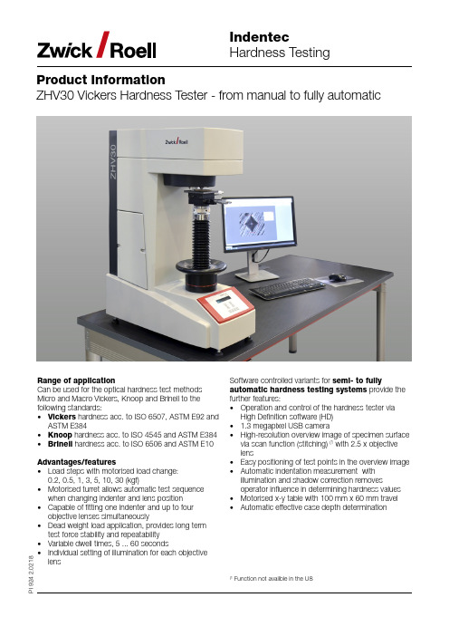
Product InformationZHV30 Vickers Hardness T ester from manual to fully automaticI 924 2.0218Range of applicationCan be used for the optical hardness test methods Micro and Macro Vickers, Knoop and Brinell to the following standards:• Vickers hardness acc. to ISO 6507, ASTM E92 and ASTM E384• Knoop hardness acc. to ISO 4545 and ASTM E384• Brinell hardness acc. to ISO 6506 and ASTM E10Advantages/features• Load steps with motorised load change: 0.2, 0.5, 1, 3, 5, 10, 30 (kgf)• Motorised turret allows automatic test sequence when changing indenter and lens position • Capable of fitting one indenter and up to four objective lenses simultaneously• Dead weight load application, provides long term test force stability and repeatability • Variable dwell times, 5 ... 60 seconds• Individual setting of illumination for each objective lensSoftware controlled variants for semi- to fullyautomatic hardness testing systems provide the further features:• Operation and control of the hardness tester via High Definition software (HD)• 1.3 megapixel USB camera• High-resolution overview image of specimen surface via scan function (stitching) (1 with 2.5 x objective lens• Easy positioning of test points in the overview image • Automatic indentation measurement with illumination and shadow correction removesoperator influence in determining hardness values • Motorised x-y table with 100 mm x 60 mm travel • Automatic effective case depth determination(1Function not availble in the USProduct InformationZHV30 Vickers Hardness T ester from manual to fully automaticHigh Definition Testing SoftwareWhen a hardness testing solution which delivers reliable, accurate and repeatable test results is needed, choose from the HD line of macro and micro hardness testing solutions - field-proven systems, offering beyond comparison capabilities and fully ASTM E 384, ISO 6507 and ISO 4545-compliant.Precise positioningWith its image of the entire specimen (Mosaics) and its annotation tools, HD Software enables you to position indents precisely where they are required.Precise, reproducible measurementsThe high image resolution of the HD Software allows measurement of indents to be precise and reproducible. Enhanced productivityThe HD Software combines ease of use, reliabilityand auto-calibration, minimizing the subjectively associated with human intervention. The system can run autonomous for hours without interruption.Sophisticated reportingThe results are automatically transferred via data interface from HD software to testXpert III - the testing software for all Zwick testing machines and instruments. According to your requirements the reports are now generated.Stage pattern windowCreate or modify traver-ses and/or patterns andtheir positions, then seethe stage move in realtime in the stage patternwindow.Results windowResults are clearlydisplayed in graphicalor tabular form. Trackand review individualindentations.Product InformationZHV30 Vickers Hardness T ester from manual to fully automaticBuilding mosaic image to a complete imagePrecise positioning at any magnificationStep 2: Set-up traverses/patternsOpen, modify, or create new traverses/patterns using reference points or lines. Traverses and patterns can be individually adjusted.T -Bar rotation toolTraverse centred in weld sample Three traverses perpendicular to edgeFive traverses perpendicular to the edge of the gearPrecise imaging with 10 x objective lens with 2.5 x objective lens with 40 x objective lensStep 4: Get resultsReview results in graphical and/or tabular format. Export results to the spreadsheet application of your choice, or to testXpert III for creating and printing standard or customized reports.Product InformationZHV30 Vickers Hardness T ester from manual to fully automaticAccessories(1PC, monitor and keyboard already included in scope of supply.。
w-20韦氏硬度计说明书英文版
w-20韦氏硬度计说明书英文版W-20 Vickers Hardness Tester ManualIntroduction:The W-20 Vickers Hardness Tester is an advanced and reliable instrument used to measure the hardness of various materials. This manual serves as a comprehensive guide to operating and maintaining the W-20 Vickers Hardness Tester. It covers the necessary procedures for conducting hardness tests, interpreting the results, and ensuring the accuracy and longevity of the instrument.Safety Precautions:1. Before operating the W-20 Vickers Hardness Tester, carefully read and understand this manual.2. Always wear appropriate personal protective equipment (PPE), including safety glasses and gloves.3. Keep the work area clean and free from clutter to avoid accidents or damage to the instrument.4. Do not touch the indenter or test piece during the hardness test.5. Turn off the power and disconnect the power cord when not in use or during maintenance.Specifications:- Maximum Test Force: 20 kgf- Test Force Application Method: Automatic loading and unloading- Test Load Dwell Time: 0 - 60 seconds- Test Force Control: Closed-loop system- Test Force Accuracy: ±1%- Test Force Retention Time: 10 - 600 seconds- Indenter: Diamond Vickers- Magnification: 100x- Measuring Range: 8-2900 HV- Test Force Selection: Manual or automaticOperating Instructions:1. Power on the W-20 Vickers Hardness Tester and wait for the system to initialize.2. Select the desired test force and enter the value using the control panel.3. Clean the surface of the test piece and securely fix it onto the testing table.4. Position the indenter above the test piece, ensuring proper alignment.5. Initiate the loading cycle and wait for the test force to be applied.6. Once the dwell time is reached, the test force will be automatically removed.7. The hardness value will be displayed on the control panel, along with the measuring range.8. Record the hardness value and repeat the process for additional tests if necessary.Maintenance and Calibration:1. Regularly clean the indenter and test table with a lint-free cloth and a mild solvent.2. Inspect the indenter for any signs of wear or damage. Replace if necessary.3. Calibrate the W-20 Vickers Hardness Tester annually or as recommended by the manufacturer.4. Perform a calibration check using certified hardness test blocks.5. Follow the provided calibration procedure to ensure accurate hardness readings.6. Keep the instrument in a clean and dust-free environment when not in use.7. Never disassemble the W-20 Vickers Hardness Tester unless authorized by a qualified technician.Troubleshooting:Problem: Inaccurate hardness readings.Solution: Ensure proper calibration and follow the recommended testing procedures. Check the indenter for wear or damage.Problem: System malfunction or error messages.Solution: Restart the instrument and refer to the troubleshooting section of the manual. If the problem persists, contact technical support.Conclusion:The W-20 Vickers Hardness Tester is a reliable and precise instrument for measuring the hardness of materials. By following the instructions provided in this manual, users can effectively conduct hardness tests and maintain the accuracy and longevity of the instrument. For any technical issues or further assistance, please refer to the contact information provided in the manual.。
各种硬度测试方法
二 硬 度1、硬度试验1.1硬度(hardness )材料抵抗弹性变形、塑性变形、划痕或破裂等一种或多种作用同时发生的能力。
最常用的有:布氏硬度、洛氏硬度、维氏硬度、努氏硬度、 肖氏硬度等。
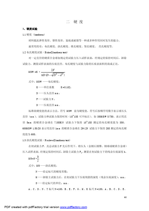
1.2布氏硬度试验(Brinell hardness test )对一定直径的硬质合金球加规定的试验力压入试样表面,经规定的保持时间后,卸除试验力,测量试样表面的压痕直径。
布氏硬度与试验力除的压痕表面积的商成正比。
HBW=K ·)(222d D D D F−−π式中:HBW ——布氏硬度;K ——单位系数 K=0.102;D ——压头直径mm ;F ——试验力N ;D ——压痕直径mm 。
标准块硬度值的表示方法,符号HBW 前为硬度值,符号后按顺序用数字表示球压头直径(mm ),试验力和试验力保持时间(10~15S 可不标注)。
如350HBW5/750。
表示用直径5mm 的硬质合金球在7.355KN 试验力下保持10~15S 测定的布氏硬度值为350,600HBW1/30/20表示用直径1mm 的硬质合金球在294.2N 试验力下保持20S 测定的布氏硬度值为600。
1.3洛氏硬度试验(Rockwell hardness test )在初试验力F 。
及总试验力F 先后作用下,将压头(金刚石圆锥、钢球或硬质合金球)压入试样表面,经规定保持时间后,卸除主试验力F 1,测量在初试验力下的残余压痕深度h 。
HR=N-sh 式中:HR ——洛氏硬度;N ——给定标尺的硬度常数;H ——卸除主试验力后,在初试验力下压痕残留的深度(残余压痕深度);mm ; S ——给定标尺的单位;mm 。
A 、C 、D 、N 、T 标尺N=100,B 、E 、F 、G 、H 、K 标尺N=130;A 、B 、C 、D 、E 、F 、G 、H 、K 标尺S=0.002。
N 、T 标尺S=0.001。
A 、C 和D 标尺洛氏硬度用硬度值、符号HR 和使用的标尺字母表示。
各类硬度介绍
具有一定形状的钢制压针, 在试验力作用下垂直压入试 样表面,当压足表面与试样 表面完全贴合时,压针尖端 面相对压足平面有一定的伸 出长度L,L越大,邵氏硬度 值越小。 HA=100-L/0.025
用具有规定尺寸、形状 和硬度铅笔芯,在750g 的负载下45°角向下压 在样品漆膜表面上,逐 渐增加铅笔的硬度直到 漆膜表面出现所定义的 各种缺陷。
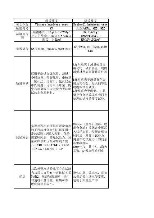
要求试样有一定的质量 其硬度值需要先测量对角线 和厚度,不适于测试小 长度,然后计算,效率不如 洛氏硬度试验高 工件。
莫氏硬度 Mohs’ scale of hardness HM
应用划痕法将棱锥形金刚钻针 刻划所试矿物的表面而发生划 痕,习惯上矿物学或宝石学上 都是用莫氏硬度。
用划痕法将棱锥形金刚钻针刻 划所试矿物的表面而发生划痕 。用测得的划痕深度分十级来 表示硬度:滑石(1)、石膏 (2)、方解石(3)、萤石 (4)磷灰石(5)、正长石 (6)、石英(7)、黄玉 (8)、刚玉(9)、金刚石 (10)
邵氏硬度 Shore hardness test HA、HD FA=56+7.66HA(gf) FD=45.36HD(gf) GB/T531,ISO7619,ASTM D1415
铅笔硬度 pencil hardness test 9B~9H F=750gf
布氏硬度 Brinell Hardness HB 1~3000kgf
适用于测试金属部件、薄板、 金属箔及工件硬化层、电镀层 、氮化层、渗碳层、氰化层的 适用领域 维氏硬度,还可用于珠宝、陶 瓷和玻璃等用大试验力无法测 试的非金属材料。
A标尺适应于测量硬度如 碳化钨、硬质合金、硬的 薄板材及表面硬化零件等 。 B标尺适应于测量有色金 属及其合金、退火钢等低 硬度零件的硬度。 C标尺适应于碳钢、工具 钢及合金钢等淬火或回火 处理的试样的硬度试验。
维克氏硬度的测试原理和要求
間接驗證
Q-Lab., Inc.
7
試片和準備要求
l
l l l l l l l
試片應依照ASTM E 3方法實施準備 : 使用拋光或其他適當的表面 準備方法以求量測的最理想準確度。表面應免於任何可以影響壓痕 或後續對角線量測的缺陷。 試片表面應平坦 : 不建議在不平坦的表面上執行測試。 壓痕尖端應能清楚顯現 : 在所有的測試時,壓痕周圍以及特別是壓 痕尖端應在顯微鏡的視野內被清楚的顯示。 試片表面不可被腐蝕 : 經腐蝕的表面能使壓痕的邊緣模糊,使得正 確量測壓痕的尺寸變得困難 。 試片的準備過程應不可產生過熱。準備過程應注意某些材料可能因 熱鑲埋而產生回火現象。 鑲埋材料必須提供試件適當的支撐 : 當試片需要鑲埋時,鑲埋材料 必須提供試件適當的支撐,使當施以荷重時試件不會移動。 試片表面與測頭之垂直角度不可超過 2O 和 1O(維克氏硬度) 試片之最小厚度為壓痕對角線長度的1.5倍。試片的最小厚度與硬度 的要求,原則上在測試後不可在試片的背面上出現任何的痕跡。當 試件被鑲埋時,此時是指試片本身之厚度,不包含鑲埋材料之厚度。
l l
Q-Lab., Inc.
5
維克氏硬度的測頭
維克氏測頭產生的壓痕,除非以非常輕的負荷,產生對角線小於約 25µm的壓痕,否則硬度值在本質上與荷重大於1kg之維克氏機器應 該是相同。只要是被測試的材料理論上相同材質,對於等方性的材料 而言,維克氏壓痕的兩個對角線尺寸上是相等的。 理想的維克氏測頭是非常光滑的,尖銳的方形體基座之錐形鑽石,並 呈136O之面角( face angles ) 。這些角度的幾何形狀差異將影響維 克氏硬度的量測值 。 維克氏測頭的四個面應 相同的傾斜於測頭的軸 線(介於±30’的範圍內) 且應相互接觸而組成一 尖銳的點。相對面 (offset)的交接線,長 度上應不超過0.5µm ( 維克氏硬度1 µm )
Hardness testing method
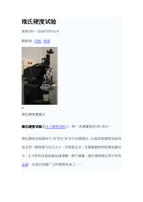
维氏硬度试验维基百科,自由的百科全书跳转到: 导航, 搜索维氏硬度测量仪维氏硬度试验是压入硬度试验之一种,其测量值用HV表示。
维氏硬度试验最初于20世纪20年代初被提出,比起其他硬度试验其优点有:硬度值与压头大小、负荷值无关;无需根据材料软硬变换压头;正方形的压痕轮廓边缘清晰,便于测量。
维氏硬度被应用于所有金属,并是应用最广泛的硬度标准之一。
只要被测材料质地均匀,维氏硬度试验可以用低负荷和小压痕得到可靠的硬度值,这样能减少材料破坏,或用于薄小的试验材料。
这一点上维氏硬度要优于布氏硬度。
另外,在硬度不高(硬度值400以下)的同一均匀材料上,维氏和布氏硬度试验得出的数值近似。
目录[隐藏]∙ 1 测量方法∙ 2 常见材料的维氏硬度∙ 3 标准∙ 4 参考文献∙ 5 参见[编辑]测量方法左为压痕在材料表面的投影,l1和l2为压痕对角线长;右为金刚石压头的侧面观,其相对面夹角为136°。
维氏硬度试验使用正四棱锥形的金刚石压头,其相对面夹角为136°。
由于其硬度极高,金刚石压头可以用于压入几乎所有材料,而且棱锥的形状使得压痕和压头本身的大小无关。
将压头用一定的负荷(试验力)压入被测材料表面。
保持负荷一定时间后,卸除负荷,测量材料表面的方形压痕之对角线长度。
对相互垂直的二对角线长度(l1和l2)取其算术平均值。
维氏硬度值的计算公式为:F = 负荷(牛顿力)S = 压痕表面积(平方毫米)α= 压头相对面夹角=136°d = 平均压痕对角线长度(毫米)报告维氏硬度值的标准格式为xHVy。
例如440HV30中,440是维氏硬度值,30指的是测量所用的负荷值(单位:千克力)。
[编辑]常见材料的维氏硬度来自[1]∙ISO 6507-1:2005 Ed. 3 Vickers hardness test Part 1: Testmethod∙ISO 6507-2:2005 Ed. 3 Vickers hardness test Part 2: Verification and calibration of testing machines∙ISO 6507-3:2005 Ed. 3 Vickers hardness test Part 3: Calibration of reference blocks∙ISO 6507-4:2005 Ed. 1 Vickers hardness test Part 4: Tables of hardness values∙GB/T4340.1-1999 金属维氏硬度第1部分:试验方法∙GB/T4340.2-1999 金属维氏硬度第2部分:硬度计的检验∙GB/T4340.3-1999 金属维氏硬度第3部分:标准硬度块的标定目录[隐藏]∙ 1 试验方法∙ 2 硬度标尺∙ 3 试验标准∙ 4 参考文献∙ 5 相關條目[编辑]试验方法使用初始试验力F0将压头垂直压入试样表面,然后施加主试验力,使用总试验力F0+F1压入并保持一段时间后,撤除主试验力,保持初始试验力。
5-2500hv技术参数
5-2500hv技术参数
HV (Vickers hardness)是一种材料硬度的测试方法,用于测量
材料的抗压强度。
在HV技术参数中,5-2500HV表示测试材料的硬
度范围,从5HV到2500HV。
这个范围涵盖了许多不同类型的材料,
从软金属到硬质合金都可以进行测试。
对于HV技术参数,首先要考虑的是测试材料的类型和厚度。
不
同类型的材料对硬度测试的要求不同,因此需要根据具体的材料特
性来选择合适的测试参数。
另外,材料的厚度也会影响测试结果,
因此在进行HV测试时需要考虑材料的厚度。
此外,HV技术参数还涉及到测试载荷和压痕的大小。
测试载荷
是指施加在材料表面的力量,而压痕的大小则取决于测试载荷和材
料的硬度。
在HV技术参数中,通常会规定测试载荷的大小和压痕的
直径范围,以确保测试结果的准确性和可靠性。
另外,HV技术参数还包括测试方法和设备规格。
不同的测试方
法会对测试结果产生影响,因此需要根据具体的测试要求选择合适
的测试方法。
同时,测试设备的规格也需要符合HV技术参数的要求,以确保测试的准确性和可重复性。
总之,HV技术参数涉及到材料的类型、厚度、测试载荷、压痕
大小、测试方法和设备规格等多个方面,需要综合考虑这些因素来
确定合适的测试参数。
这样才能确保HV测试结果的准确性和可靠性。
维氏硬度mpa
维氏硬度(MPa)1. 硬度的定义和意义硬度是材料抵抗外界力量侵入的能力,是评价材料抗压性能的重要指标之一。
维氏硬度(Vickers hardness)是一种常用的硬度测试方法,它通过在材料表面施加一定压力,测量压痕的对角线长度来计算硬度值。
维氏硬度是以瑞士工程师Georges Vickers的名字命名的。
2. 维氏硬度测试原理维氏硬度测试使用一块金刚石或硬质合金锥形压头,施加在测试材料表面上。
压头施加的压力通常在几千兆帕(MPa)到几十兆帕之间。
在施加压力的同时,测量压头对材料产生的压痕的两个对角线长度。
通过计算这两个长度的平均值,然后根据一定的公式计算出维氏硬度值。
3. 维氏硬度测试仪器和操作步骤维氏硬度测试通常使用维氏硬度计来进行,该仪器由压头、显微镜、测量尺等组成。
测试步骤如下:•将测试样品放置在硬度计的测试台上,确保表面平整、干净。
•调整显微镜,使其对焦在测试样品表面。
•选择适当的压头,并将其安装在硬度计上。
•轻轻将压头接触到测试样品表面,然后施加一定的压力。
•压头施加压力一定时间后,松开压力。
•使用显微镜观察压痕,并测量两个对角线的长度。
•计算维氏硬度值,通常使用公式:硬度值 = 压力 / 压痕面积。
4. 维氏硬度与材料性能的关系维氏硬度是衡量材料抗压性能的重要指标之一。
硬度值越高,表示材料越难被压入,具有较好的抗压性能。
维氏硬度值可以用来比较不同材料的硬度,以选择合适的材料用于特定的工程应用。
此外,维氏硬度还可以用来评估材料的耐磨性、耐磨损性和耐腐蚀性能。
硬度值高的材料通常具有较好的耐磨性和耐腐蚀性,适用于需要经受高压、高温或腐蚀环境的工程应用。
5. 维氏硬度的应用领域维氏硬度测试广泛应用于材料科学、工程设计和质量控制等领域。
以下是一些常见的应用领域:•金属材料:维氏硬度测试可以用来评估金属材料的硬度和强度,以选择合适的金属材料用于制造机械零件、工具和设备。
•陶瓷材料:维氏硬度测试可以用来评估陶瓷材料的硬度和脆性,以选择合适的陶瓷材料用于制造陶瓷零件、耐磨件和瓷砖等。
各种硬度计的原理及应用
各种硬度计的原理及应用硬度计是一种用来测量物体硬度的仪器,根据不同的原理和方法,硬度计可以分为多种类型。
下面将介绍几种常见的硬度计、其原理和应用。
1. 布氏硬度计(Brinell Hardness Tester):布氏硬度计是最早应用的一种硬度计,广泛用于金属材料的硬度测试。
其原理是通过在被测样品上施加一定的载荷,由钢球压入样品表面,然后测量钢球对样品的压痕直径。
布氏硬度的数值为载荷除以压痕表面积。
布氏硬度计适用于各种金属材料的硬度测试,特别是对有较大颗粒的金属材料。
广泛应用于钢铁、铝合金、铜合金等材料的硬度测试。
2. 维氏硬度计(Vickers Hardness Tester):维氏硬度计是一种常见的万能硬度计,可以用于各种金属和非金属材料的硬度测试。
其原理是通过在被测样品上施加一定的载荷,在样品表面形成一个类似于菱形的压痕,然后测量压痕对角线的长度,从而计算出硬度值。
维氏硬度计适用于各种各样的材料,包括金属、陶瓷、玻璃等。
广泛应用于材料科学、机械制造、质量控制等领域。
3. 洛氏硬度计(Rockwell Hardness Tester):洛氏硬度计是一种常用的硬度计,适用于各种金属材料的硬度测试。
其原理是通过在被测样品上施加不同深度的载荷,然后测量应力下降后残余压入量,从而得出硬度值。
洛氏硬度计包括洛氏A、B、C三种硬度计,分别适用于不同材料硬度的测试。
洛氏硬度计广泛应用于金属材料的硬度测量,特别是薄板和涂层材料的表面硬度测试。
4. 莱氏硬度计(Leeb Hardness Tester):莱氏硬度计是一种便携式硬度计,适用于金属材料的硬度测试。
其原理是通过在被测样品上施加一定的载荷,产生一定的振动波动,然后通过测量振动波动的衰减程度,计算出硬度值。
莱氏硬度计具有简单、快速、便携等特点,广泛应用于现场检测、高海拔地区测试、狭窄空间测试等领域。
以上介绍的是四种常见的硬度计及其原理和应用。
不同的硬度计适用于不同类型的材料和测试场景,选择合适的硬度计可以有效地测量和比较材料的硬度,从而为科学研究、工程设计、质量控制等提供可靠的数据支持。
各种硬度计原理构造及应用
各种硬度计原理构造及应用硬度计是一种用来测量物质硬度的仪器。
它广泛应用于材料科学、工程和制造领域。
硬度测量是对材料的抗压能力或抗表面变形性的评估。
本文将介绍几种常见的硬度计,包括洛氏硬度计、布氏硬度计、维氏硬度计和显微硬度计,并分析其原理、构造和应用。
1.洛氏硬度计(Rockwell Hardness Tester)洛氏硬度计是一种广泛应用于金属材料的硬度测试仪器。
它利用了一根金刚石球或钨碳化钨圆锥压下物体表面,然后测量压入深度的差异来确定硬度值。
洛氏硬度计具有简单、快速和准确的特点,适用于各种金属材料的硬度测试。
洛氏硬度计的构造包括一个测量头、负载加装装置、显微镜和硬度刻度盘。
在测试时,测量头将负载施加在试样上,然后使用显微镜观察压入深度的变化,并读取硬度值。
2.布氏硬度计(Brinell Hardness Tester)布氏硬度计是一种常见的金属硬度测试仪器,它通过在试样表面施加一定的压力,使用一个硬度球头来测量试样的硬度。
布氏硬度计适用于大部分金属材料的硬度测试。
布氏硬度计的构造包括一个试验头、负载施加装置和物镜。
在测试时,试验头将一定的负载施加在试样表面上,硬度球头形成的压痕的尺寸用物镜观察,并通过一份硬度表来得出硬度值。
3.维氏硬度计(Vickers Hardness Tester)维氏硬度计是一种常用于金属和陶瓷材料的硬度测试仪器。
它主要用于测量材料的显微硬度,即对于较小的硬度痕迹。
维氏硬度计的构造包括一个负载施加装置、一个钻石或钨碳化钨的金字塔形压头和一个显微镜。
在测试时,负载施加装置将一定负载施加在试样表面上,压头形成的硬度痕迹的对角线长度用显微镜观察,并通过一份硬度表来确定硬度值。
4.显微硬度计(Microhardness Tester)显微硬度计是一种特殊的硬度测试仪器,主要用于测量材料的显微硬度,比如薄片、涂层和附着物等。
显微硬度计适用于对小硬度痕迹的测量,分析和质量控制。
- 1、下载文档前请自行甄别文档内容的完整性,平台不提供额外的编辑、内容补充、找答案等附加服务。
- 2、"仅部分预览"的文档,不可在线预览部分如存在完整性等问题,可反馈申请退款(可完整预览的文档不适用该条件!)。
- 3、如文档侵犯您的权益,请联系客服反馈,我们会尽快为您处理(人工客服工作时间:9:00-18:30)。
Purpose: To ensure proper usage and daily maintenance of Vickers
Hardness Tester
目的:正确使用V 氏硬度计进行试样的硬度测量,以及硬度计的日常保养。
Step1: Turn on the switch of the computer.
第一步:首先开启电脑电源。
Step2: Turn on the switch of the control unit (ARS-900) and then the
“standby ” switch (at the center of the rear surface) of the hardness tester. (Otherwise tester will not work; we should turn off the control unit and turn on it again.)
第二步:打开ARS-900控制器和硬度计的电源。
Step3: Insert specimen by using screw mechanism. The specimen ’s face
must be parallel with jig face. Tighten the specimen in place until there is no space between the specimen face and jig face. Then set it on the table.
第三步:将试样放入夹具中,通过螺纹旋紧,直至试样与夹具没有空隙,试样
表面与夹具表面必须保证平行。
安装完成后置于硬度计的工作台上。
Printer Eyepiece Control unit
Optical path changeover rod Focus knob Objective lens and indenter
Screen Table
Standby switch (rear surface)
Computer
Step4: Move the sample close to the lens as watching it directly. Be
careful to prevent the specimen ’s surface from hitting the lens. When the specimen is close to the lens, change the optical path changeover rod (IN: eyepiece, OUT: screen). Then bring the specimen ’s surface into focus as watching the screen.
第四步:调整试样与物镜距离,注意避免试样表面碰到物镜。
调整试样表面与
物镜适当距离后通过光路转换拉杆切换到电脑屏幕图像,并对试样进行对焦。
Step5: Pattern setting (Detailed steps referred to procedure 2).
Step5A: Check the position, if it is OK, click “Auto.Start ”, and then
machine will work automatically.
Step5B: If not, reset the dot position. And repeat Step5A.
Each dot will take about 10s. Wait until all dots are finished.
第五步: 进行路径设定(见说明书)。
检查打点位置,如果设定正确,点击“自
动开始”按钮。
仪器将开始自动进行打点。
Specimen face
Jig face Screw mechanism
Good Jig base
No gap Gap
No good
Step6: Click “Initial Setting…(T)”and then click “Indenter Center…(C)”.
Fit the center line with the cross cursor to the indentation center and then click the indentation mark. Then you can click “Read” to get the hardness data.
(If the indentation on the screen is deviated from the center line, automatic measurement cannot be done correctly.)
第六步:压子中心调整。
(如果十字线与压痕中心不能重合测量数据会有偏差。
)Step7: Open the parameter template, change and store the data of the “Test condition”or “Technical reports”, or you can access the stored data of the “Test condition”or “Technical reports”and display them according to each sample specimen.
第七步:打开参数设定模板,修正并保存“试验条件”以及“技术报告”,或者根据每个试样从已存储的档案中直接调取。
Step8: Outputting the report after measurement. Click “report”on the “automatic measurement” window, select “technical report”, and click “Print”.
第八步:输出测量数据,选中打印格式为“检查成绩书”。
Step9: Store the measurement data.
第九步:存储试验数据。
Step10: When the measurement is finished, turn off the power and remember to cover the tester.
第十步:实验结束,关闭电源,并盖好防尘罩。