电子压力传感器作业指导书
计量检测与仪器作业指导书

计量检测与仪器作业指导书第1章计量检测基础理论 (4)1.1 计量的概念与分类 (4)1.1.1 概念 (4)1.1.2 分类 (4)1.2 检测方法与原理 (4)1.2.1 机械检测法 (4)1.2.2 电气检测法 (4)1.2.3 光学检测法 (5)1.2.4 声学检测法 (5)1.3 测量误差与数据处理 (5)1.3.1 测量误差 (5)1.3.2 数据处理 (5)第2章计量法规与标准 (5)2.1 计量法规体系 (5)2.1.1 计量法规概述 (5)2.1.2 计量法规体系构成 (5)2.1.3 计量法规体系的主要内容 (6)2.2 计量检定规程 (6)2.2.1 计量检定规程概述 (6)2.2.2 计量检定规程的制定原则 (6)2.2.3 计量检定规程的主要内容 (6)2.3 计量标准及建标 (7)2.3.1 计量标准概述 (7)2.3.2 计量标准的分类 (7)2.3.3 计量标准的建立与维护 (7)2.3.4 计量标准的作用 (7)第3章计量检测仪器 (7)3.1 计量检测仪器概述 (7)3.2 常用计量检测仪器 (7)3.2.1 长度测量仪器 (7)3.2.2 角度测量仪器 (8)3.2.3 重量测量仪器 (8)3.2.4 硬度测量仪器 (8)3.2.5 速度测量仪器 (8)3.2.6 温度测量仪器 (8)3.2.7 压力测量仪器 (8)3.2.8 流量测量仪器 (8)3.3 计量检测仪器选用与维护 (8)3.3.1 选用原则 (8)3.3.2 仪器维护 (8)第4章长度计量 (9)4.1.1 长度单位 (9)4.1.2 测量误差 (9)4.1.3 长度计量器具选用原则 (9)4.2 长度计量器具 (10)4.2.1 机械式长度计量器具 (10)4.2.2 电子式长度计量器具 (10)4.3 长度测量方法 (10)4.3.1 直接测量法 (10)4.3.2 间接测量法 (10)第5章力学计量 (11)5.1 力学计量基本概念 (11)5.1.1 力的单位 (11)5.1.2 测量准确度 (11)5.1.3 测量不确定度 (11)5.2 力学计量器具 (11)5.2.1 机械式测力计 (11)5.2.2 电子测力计 (11)5.2.3 液压测力计 (12)5.3 力学测量方法 (12)5.3.1 静态测量法 (12)5.3.2 动态测量法 (12)5.3.3 振动测量法 (12)5.3.4 转矩测量法 (12)5.3.5 压力测量法 (12)第6章热工计量 (12)6.1 热工计量基本概念 (12)6.2 热工计量器具 (13)6.2.1 温度计 (13)6.2.2 热量计 (13)6.2.3 热容量计 (13)6.3 热工测量方法 (13)6.3.1 直接测量法 (13)6.3.2 间接测量法 (13)第7章电磁计量 (13)7.1 电磁计量基本概念 (13)7.1.1 量纲 (14)7.1.2 单位 (14)7.1.3 标准 (14)7.2 电磁计量器具 (14)7.2.1 分类 (14)7.2.2 原理 (14)7.2.3 功能 (14)7.3 电磁测量方法 (15)7.3.2 间接测量法 (15)7.3.3 比较测量法 (15)7.3.4 转换测量法 (15)7.3.5 非接触测量法 (15)7.3.6 数字化测量法 (15)第8章光学计量 (15)8.1 光学计量基本概念 (15)8.1.1 光学量的定义 (15)8.1.2 光学测量的不确定度评定 (16)8.1.3 光学计量标准的建立与维护 (16)8.2 光学计量器具 (16)8.2.1 光谱仪 (16)8.2.2 干涉仪 (16)8.2.3 激光测距仪 (16)8.2.4 光学厚度计 (16)8.3 光学测量方法 (16)8.3.1 直接测量法 (16)8.3.2 间接测量法 (17)第9章声学计量 (17)9.1 声学计量基本概念 (17)9.1.1 声学计量定义 (17)9.1.2 声学计量单位 (17)9.1.3 声学计量标准 (17)9.2 声学计量器具 (17)9.2.1 声级计 (17)9.2.2 声强计 (17)9.2.3 频谱分析仪 (17)9.2.4 声学传感器 (17)9.3 声学测量方法 (17)9.3.1 声压级测量 (17)9.3.2 声强测量 (18)9.3.3 声音频率分析 (18)9.3.4 声学传感器测量 (18)9.3.5 声学测量不确定度分析 (18)第10章计量检测质量控制 (18)10.1 计量检测质量管理体系 (18)10.1.1 质量管理体系建立 (18)10.1.2 质量管理体系运行 (18)10.1.3 质量管理体系持续改进 (18)10.2 计量检测过程控制 (18)10.2.1 检测前准备 (18)10.2.2 检测过程控制 (18)10.2.3 检测后处理 (19)10.3 计量检测数据分析与处理 (19)10.3.1 数据收集与整理 (19)10.3.2 数据分析方法 (19)10.3.3 数据处理过程 (19)10.4 计量检测不确定度评定与表示 (19)10.4.1 不确定度评定的基本原理 (19)10.4.2 不确定度评定方法 (19)10.4.3 不确定度表示 (19)第1章计量检测基础理论1.1 计量的概念与分类计量学是研究测量方法和测量单位的科学。
传感器实验指导书电子版
实验一金属箔式应变片单臂电桥性能实验一、实验目的:了解金属箔式应变片的应变效应,单臂电桥工作原理和性能。
二、基本原理:电阻丝在外力作用下发生机械变形时,其电阻值发生变化,这就是电阻应变效应,描述电阻应变效应的关系式为:ΔR/R=Kε式中ΔR/R为电阻丝的电阻相对变化值,K为应变灵敏系数,ε=Δl/l为电阻丝长度相对变化。
金属箔式应变片是通过光刻、腐蚀等工艺制成的应变敏感元件,用它来转换被测部位的受力大小及状态,通过电桥原理完成电阻到电压的比例变化,输出电压U0=EKε(E为供桥电压),对单臂电桥而言,电桥输出电压,U01=EKε/4。
(E为供桥电压)。
三、需用器件与单元:应变式传感器实验模板、应变式传感器、砝码(每只约20g)、数显表、±15V电源、±4V电源、万用表(自备)。
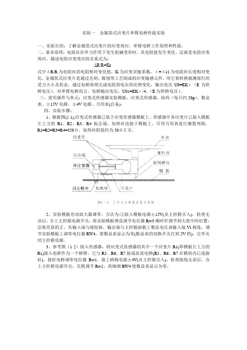
四、实验步骤:1、根据图(1-1),应变式传感器已装于应变传感器模板上。
传感器中各应变片已接入模板左上方的R1、R2、R3、R4标志端。
加热丝也接于模板上,可用万用表进行测量判别,R1=R2=R3=R4=350Ω,加热丝阻值约为50Ω左右。
2、实验模板差动放大器调零,方法为:①接入模板电源±15V(从主控箱引入),检查无误后,合上主控箱电源开关,将实验模板增益调节电位器Rw3顺时针调节到大致中间位置,②将差放的正、负输入端与地短接,输出端与主控箱面板上数显电压表输入端Vi相连,调节实验模板上调零电位器RW4,使数显表显示为零(数显表的切换开关打到2V档),完毕关闭主控箱电源。
3、参考图(1-2)接入传感器,将应变式传感器的其中一个应变片R1(即模板左上方的R1)接入电桥作为一个桥臂,它与R5、R6、R7接成直流电桥(R5、R6、R7在模块内已连接好),接好电桥调零电位器Rw1,接上桥路电源±4V(从主控箱引入),检查接线无误后,合上主控箱电源开关,先粗调节Rw1,再细调RW4使数显表显示为零。
苹果电子 ACC5000 压力传感器说明书

PX209, PX219, PXM209, PXM219Pressure TransducersServicing North America:U.S.A.:One Omega Drive, Box 4047ISO 9001 CertifiedStamford, CT 06907-0047Tel: (203) 359-1660FAX: (203) 359-7700e-mail:**************Canada:976 BergarLaval (Quebec) H7L 5A1, Canada Tel: (514) 856-6928FAX: (514) 856-6886e-mail:*************For immediate technical or application assistance:U.S.A. and Canada:Sales Service: 1-800-826-6342/1-800-TC-OMEGACustomer Service: 1-800-622-2378/1-800-622-BESTEngineering Service: 1-800-872-9436/1-800-USA-WHENMexico:En Espan ˜ol: (001) 203-359-7803FAX: (001) 203-359-7807e-mail:*******************************.mxServicing Europe:Czech Republic:Frystatska 184, 733 01 Karviná, Czech Republic Tel: +420 (0)59 6311899FAX: +420 (0)59 6311114Toll Free: 0800-1-66342e-mail:*****************Germany/Austria:Daimlerstrasse 26, D-75392 Deckenpfronn, Germany Tel:+ 49 (0)7056 9398-0FAX: +49 (0)7056 9398-29TollFreeinGermany************e-mail:*************United Kingdom:One Omega Drive, River Bend Technology Centre ISO 9002 CertifiedNorthbank, Irlam, Manchester M44 5BD United Kingdom Tel: +44 (0)161 777 6611FAX: +44 (0)161 777 6622Toll Free in United Kingdom: 0800-488-488e-mail:**************.ukIt is the policy of OMEGA Engineering, Inc. to comply with all worldwide safety and EMC/EMIregulations that apply. OMEGA is constantly pursuing certification of its products to the EuropeanNew Approach Directives. OMEGA will add the CE mark to every appropriate device upon certification.The information contained in this document is believed to be correct, but OMEGA accepts no liability for any errors it contains, and reserves the right to alter specifications without notice.WARNING:These products are not designed for use in, and should not be used for, human applications.DIMENSIONS mm (in)Cable shielding must be terminated at the meter to earth ground to comply with CE.DIMENSIONS WIRINGWARRANTY/DISCLAIMEROMEGA ENGINEERING, INC. warrants this unit to be free of defects in materials and workmanship for a period of 37months from date of purchase. OMEGA’s WARRANT Y adds an additional one (1) month grace period to the normal three (3) year product warranty to cover handling and shipping time. T his ensures that OMEGA’s customers receive maximum coverage on each product.If the unit malfunctions, it must be returned to the factory for evaluation. OMEGA’s Customer Service Department will issue an Authorized Return (AR) number immediately upon phone or written request. Upon examination by OMEGA, if the unit is found to be defective, it will be repaired or replaced at no charge. OMEGA’s WARRANT Y does not apply to defects resulting from any action of the purchaser, including but not limited to mishandling, improper interfacing,operation outside of design limits, improper repair, or unauthorized modification. T his WARRANTY is VOID if the unit shows evidence of having been tampered with or shows evidence of having been damaged as a result of excessive corrosion; or current, heat, moisture or vibra-tion; improper specification; misapplication; misuse or other operating conditions outside of OMEGA’s control. Components in which wear is not warranted, include but are not limited to contact points, fuses, and triacs.OMEGA is pleased to offer suggestions on the use of its various products. However, OMEGA neither assumes responsibility for any omissions or errors nor assumes liability for any damages that result from the use of its products in accordance with information provided by OMEGA, either verbal or written. OMEGA warrants only that the parts manufactured by the company will be as specified and free of defects. OMEGA MAKES NO OTHER WARRANTIES OR REPRESENTATIONS OF ANY KIND WHATSOEVER,EXPRESSED OR IMPLIED, EXCEPT THAT OF TITLE, AND ALL IMPLIED WARRANTIES INCLUDING ANY WARRANTY OF MERCHANTABILITY AND FITNESS FOR A PARTICULAR PURPOSE ARE HEREBY DISCLAIMED. LIMITATION OF LIABILITY: The remedies of pur-chaser set forth herein are exclusive, and the total liability of OMEGA with respect to this order, whether based on contract, warranty, negligence, indemnification, strict liability or otherwise, shall not exceed the purchase price of the component upon which liability is based. In no event shall OMEGA be liable for consequential, incidental or special damages.CONDITIONS: Equipment sold by OMEGA is not intended to be used, nor shall it be used: (1) as a “Basic Component” under 10 CFR 21 (NRC), used in or with any nuclear installation or activity;or (2) in medical applications or used on humans. Should any Product(s) be used in or with any nuclear installation or activity, medical application, used on humans, or misused in any way,OMEGA assumes no responsibility as set forth in our basic WARRANTY/DISCLAIMER language,and, additionally, purchaser will indemnify OMEGA and hold OMEGA harmless from any liability or damage whatsoever arising out of the use of the Product(s) in such a manner.RETURN REQUESTS/INQUIRIESDirect all warranty and repair requests/inquiries to the OMEGA Customer Service Department.BEFORE RET URNING ANY PRODUCT (S) T O OMEGA, PURCHASER MUST OBTAIN AN AUT HORIZED RET URN (AR) NUMBER FROM OMEGA’S CUST OMER SERVICE DEPART MENT (IN ORDER T O AVOID PROCESSING DELAYS). T he assigned AR number should then be marked on the outside of the return package and on any correspondence.The purchaser is responsible for shipping charges, freight, insurance and proper packaging to prevent breakage in transit.FOR WARRANTY RETURNS, please have the following information available BEFORE contacting OMEGA:1.Purchase Order number under which the product was PURCHASED,2.Model and serial number of the product under warranty, and3.Repair instructions and/or specific problems relative to the product.FOR NON-WARRANTY REPAIRS,consult OMEGA for current repair charges. Have the following information available BEFORE contacting OMEGA:1. Purchase Order number to cover the COST of the repair,2.Model and serial number of the product, and3.Repair instructions and/or specific problems relative to the product.OMEGA’s policy is to make running changes, not model changes, whenever an improvement is possible. This affords our customers the latest in technology and engineering.OMEGA is a registered trademark of OMEGA ENGINEERING, INC.© Copyright 2007 OMEGA ENGINEERING, INC. All rights reserved. This document may not be copied, photocopied,reproduced, translated, or reduced to any electronic medium or machine-readable form, in whole or in part, without the prior written consent of OMEGA ENGINEERING, INC.。
Fisher 电子压力传感器 IP510 Series 说明书

U Hazardous Location and Intrinsically Safe RatingsU NEMA 4X (IP66)U 0.1% Accuracy TypicalU Closed-Loop Pressure Feedback ControlU Built-In Volume Booster Provides Flow Up to 12 SCFMU Easy Access to Zero and SpanU Damping Pot Prevents Overshoot and HuntingU Low Air ConsumptionU Mount at Any AngleU Compact and LightweightU Virtually No Sensitivity to Supply Pressure ChangesU Removable Orifice for Easy MaintenanceU Buna-N Seals StandardU Fluorocarbon Seals OptionalCurrent to Pressure (I/P) andVoltage to Pressure (E/P) ModelsEP511-X30, shown smaller than actual size.HEAVY-DUTY ELECTROPNEUMATIC CONVERTERS IP510-X27, shown smaller than actual size.IP510 SeriesSPECIFICATIONS Accuracy: Typical: ±0.1% of output span Maximum: ±0.25% of output span Hysteresis: Typical: ±0.01% of output span Maximum: ±0.10% of output span Deadband: No effect The IP510/EP510 Series is a patented family of electro-pneumatic instruments used to reduce a supply pressure to a regulated output pressure that is directly proportional to a 2-wire current or 3-wire voltage input. This design incorporates closed-loop sensing of the output pressure to achieve excellent accuracy and vibration stability. It also features a unique damping circuit that can be adjusted to prevent overshoot and actuator “hunting.” Model selection includes general purpose NEMA 1 (IP00) and watertight/corrosion-resistant NEMA 4X (IP66). All models carry hazardous location and intrinsically safe ratings.Repeatability: Typical: ±0.01% of output span Maximum: ±0.10% of output span Ambient Temperature Effect: Typical: ±0.004% of nominal span per ºF Maximum: ±0.022% of nominal span per ºF Span: Typical: 0.013% of calibrated span per ºF Maximum: 0.022% of calibrated span per ºF Temperature Effect: ≤0.02%/ºF, zero and span effects combinedHEAVY-DUTY ELECTROPNEUMATIC CONVERTERS COIL COIL WIRE DAMPING POTENTIOMETER TERMINAL BLOCK GROUND SCREW NPT ELECTRICAL PORT 1⁄8GAUGE PORT REMOVABLE ORIFICE。
E+H压力传感器调试说明书

E+H压力传感器调试说明书仪表上电后显示:MEASURE VALUEXXX.XX m3按E进入组菜单,显示GROUP SLECTIONLANGUAGEMEASURE MODEQUICK SETUPOPERATING MENU按-号,到MEASURE MODE,按E选中,并出现在它之前,再按E,进入出现:PRESSURELEVELFLOW按-号,到LEVEL,按E选中,并出现在它之前,再按E,进入出现:LEVEL EASY PRESSURELEVEL EASY HEIGHTLEVEL STANDARD按-号,到LEVEL STANDARD,按E选中,并出现在它之前,再按E,返回MEASURE MODE,按-号,直到显示GROUP SLECTIONOPERATING MENULANGUAGEMEASURE MODE按E选中,并出现在它之前,再按E进入,出现:SETTINGPOSITION ADJUST TMENTPOS.ZERO ADJUST按E进入,按-号直到出现:BASIC SETUP按E进入,出现:PRESS.ENG.UNITm bar按E确认,出现:LinearPressure linearizedHeight linearized按-号,到Pressure linearized,按E选中,并出现在它之前,再按E,出现:PRESSURE & %PRESSURE & VOLUMEPRESSURE & MASS按-号,到PRESSURE & VOLUME,按E选中,并出现在它之前,再按E,出现:UNIT VOLUMEM3按E确认,并出现:HYDR. PRESS MIN.0mbar按E,出现:HYDR. PRESS MAX.388.1mbar(这里输入你测量的高度)如果出来的数字不是388.1,就用+或-改为388.1,再按E确认,出现:DAMPING VALUE2.0S按E确认,系统自动返回OPERATING MENU界面,按E再次进入:还是进入SETTING,再按E进入按-号,直到选中LINEARIZATION,按E确认,并进入:TANK CONTENT MIN0 M3按E确认,出现:TANK CONTENT MAX16.788M3(这里输入罐体的实际容积)如果这个值不是这个值就用+或-号把数值修改为这个值,然后按E确认,并出现:Measuring TableEditor Table按-号,直到选中Editor Table,按E确认,再按E进入:接下来的画面中我们需要选中的是:Manual,选中这个参数并按E确认,进入下一个参数:NEW TABLE,选中这个参数并按E确认,开始表格填写,从NEW TABLE开始就是建立表格了,表格的数据在最后以表格的形式给出。
柳木川电子有限公司EJA系列电子压力传感器用户手册说明书

Y okogawa Electric Corporation IM 01C22A00-12E 2nd EditionIM 01C22A00-12E1.INTRODUCTIONThank you for purchasing the DPharp electronic pressure transmitter.This manual contains important note and handling cautions for the DPharp EJA Series DifferentialPressure/Pressure Transmitters with NEPSI certifica-tion, option code /NS2 and /NF2.Refer to each of the following user’s manuals for standard specifications, functions, handling cautions,and operations, etc.Table 1 List of Individual User’s ManualsEJA110A, EJA120A, and EJA130A IM 01C21B01-01E EJA210A and EJA220A IM 01C21C01-01E EJA310A, EJA430A, and EJA440A IM 01C21D01-01E EJA510A and EJA530A IM 01C21F01-01E EJA110 and EJA120 IM 01C22B01-01E EJA210 and EJA220 IM 01C22C01-01E EJA310 and EJA430 IM 01C22D01-01E EJA118W, EJA118N, and EJA118Y IM 01C22H01-01E EJA438W and EJA438N IM 01C22J01-01E EJA115 IM 01C22K01-01ET01.EPSDocument No.Model2. NEPSI Certificationa.NEPSI Intrinsically Safe TypeCaution for NEPSI Intrinsically safe type.Note 1.Model EJA Series differential, gauge, andabsolute pressure transmitters withoptional code /NS2 are applicable for use in hazardous locations• Applicable Standard: GB3836.1:2000,GB3836.4:2000• Type of Protection and Marking Code: Ex ia IIC T4• Ambient Temperature :–40 to 60°C • Max. Process Temp.: 120°C • Enclosure: IP67Note 2.Entity Parameters• Intrinsically safe ratings are as follows:Maximum Input Voltage (Ui) = 30 V Maximum Input Current (Ii) = 165 mA Maximum Input Power (Pi) = 0.9 WMaximum Internal Capacitance (Ci) = 22.5 nF Maximum Internal Inductance (Li) = 730 µH Maximum Internal Inductance (Li) = 730 µH • Installation RequirementsUo ≤ Ui, Io ≤ Ii, Po ≤ Pi,Co ≥ Ci + Ccable, Lo ≥ Li + Lcable Uo, Io, Po, Co, and Lo are parameters of barrier.Note 3.Installation• In any safety barreir used output current must be limited by a resistor 'R' such that Io=Uo/R.• The safety barrier must be NEPSI certified.• Input voltage of the safety barrier must be less than 250 Vrms/Vdc.• The instrument modification or parts replacement by other than authorized representative of Yokogawa Electric Corporation and will void NEPSI Intrinsically safe certification.• The cable entry devices and blanking elements for type n shall be of a certified type providing a level of ingress protection of at least IP54, suitable for the conditions of use and correctly installed.• Electrical Connection:The type of electrical connection is stamped near the electrical connection port according to the following marking.Note 4. Operation • WARNING:WHEN AMBIENT TEMPERATURE ≥ 55°C,USE THE HEAT-RESISTING CABLES ≥ 90°C.Note 5. Special Conditions for Safe Use • WARNING:IN THE CASE WHERE THE ENCLOSURE OF THE PRESSURE TRANSMITTER IS MADE OF ALUMINUM, IF IT IS MOUNTED IN AN AREA WHERE THE USE OF ZONE 0 IS REQUIRED,IT MUST BE INSTALLED SUCH, THAT, EVEN IN THE EVENT OF RARE INCIDENTS, IGNI-TION SOURCES DUE TO IMPACT AND FRICTION SPARKS ARE EXCLUDED.[Intrinsically Safe]FD No. IM 01C22A00-12E 2nd Edition: June 2011(YK)All Rights Reserved, Copyright © 2007, Yokogawa Electric Corporationb.NEPSI Flameproof TypeCaution for NEPSI flameproof type.Note 1.Model EJA Series differential, gauge, andabsolute pressure transmitters withoptional code /NF2 are applicable for usein hazardous locations:• Applicable Standard: GB3836.1:2000,GB3836.2:2000• Type of Protection and Marking Code:Ex d IIC T6...T4• Enclosure: IP67• Maximum Process Temperature: 120°C (T4),100°C (T5), 85°C (T6)• Ambient Temperature: –40 to 75°C (T4), –40 to80°C (T5), –40 to 75°C (T6)• Supply Voltage: 42 V dc max.• Output Signal: 4 to 20 mA dcNote 2.Wiring• In hazardous locations, the cable entry devices shallbe of a certified flameproof type, suitable for theconditions of use and correctly installed.• Unused apertures shall be closed with suitableflameproof certified blanking elements. (The plugattached is certificated as the flame proof IP67 as apart of this apparatus.)• In case of ANSI 1/2 NPT plug, ANSI hexagonalwrench should be applied to screw in.Note 3. Operation• WARNING:AFTER DE-ENERGIZING, DELAY 10 MINUTESBEFORE OPENING.• WARNING:WHEN AMBIENT TEMPERATURE ≥ 70°C,USE THE HEAT-RESISTING CABLES ≥ 90°C.• Take care not to generate mechanical sparkingwhen accessing to the instrument and peripheraldevices in a hazardous location.Note 4. Maintenance and Repair• The instrument modification or parts replacementby other than authorized representative ofYokogawa Electric Corporation is prohibited andwill void NEPSI Certification.Revision RecordJanuary 20071st edition New PublicationJune 20112nd edition Delete certificaion No.IM 01C22A00-12E。
压力变送器作业指导书
压力变送器作业指导书一、目的:帮助和指导班组有效处理压力变送器故障,对存在的危险进行分析,并采取相应的安全措施进行规避,以确保作业安全和质量。
二、适用范围:各装置中的压力变送器。
三、采用标准:本作业指导书标准来自《工业自动化仪表验收规范(GB50093-2013)》四、工作原理:压力变送器各有两种类型。
一种是模拟型,另一种是智能型。
它们用来测量各种介质的压力,并将这些参数转换成4~20mA DC电流信号,以进行远距离传送,仪表的所有调整都集中在传送部件上,因而调整方便,准确。
图1-4.1是压力变送器的工作原理框图。
检测部件将输入压力的变化转换为相应的电容变化,再经传送部件中的电子线路转化成4~20mA DC的直流电流输出。
图1-4.1五、作业步骤、危险分析、安全措施:接到工艺电话,首先立即赶赴主控室和现场,观察、询问故障现象,掌握第一手材料,然后到现场作JHA分析,并向工艺车间申请相关作业票,最后待工艺监护人员到现场时,才开始动手作业,其步骤如下:(表1-4.1)表1-4.1六、常见故障现象分析、判断、处理:(表1-4.2)表1-4.2七、使用的工具和劳保要求:使用的工具:个人工具、10”管钳、万用表、手操器;拆卸三阀组时,还需要10”扳手、14”梅花扳手、一块干净抹布或塑料薄膜;劳保要求:工作服着装,戴好安全帽、护目眼睛和劳保手套(或防酸碱手套);甚至还需要氧气呼吸器、安全带;拆卸时,必须要佩戴防护面罩。
附录:压力变送器校验步骤:1.回零检查:1)关闭二次阀;2)将表堵头螺钉松开排堵;3)检查仪表零位,若超差调整零位;4)投用及清洁现场。
2.变送器零位、量程校验:校验准备:标准压力校验器、精密压力表、标准电流表、24V DC 电源及连接件、导线等。
1)将仪表正压室通大气,接通电源稳定3min后,将阻尼时间置最小,此时变送器为4mA否则调整零点螺钉,使之输出为4mA 2)给变送器正压室输入量程信号,负压通大气,变送器输出为20 mA , 若有偏差调整量程螺钉使之输出为20mA。
电子压力计使用说明书
电子压力计使用说明书一、产品简介电子压力计是一种用于测量气体或液体压力的仪器,采用先进的电子技术和传感器,具有高精度、高稳定性和可靠性等特点。
本说明书将详细介绍电子压力计的使用方法及注意事项,帮助用户正确使用该产品。
二、产品结构电子压力计由以下几个部分组成:1. 具有数字显示屏的主控面板:用于显示测量结果和设定参数。
2. 压力传感器:接收被测介质的压力并将其转换成电信号。
3. 连接线:连接主控面板和传感器。
4. 电源供应器:为电子压力计提供电力支持。
三、使用方法1. 将主控面板和传感器连接好,并确保连接稳固可靠。
2. 打开电源供应器,使其为电子压力计提供电力。
3. 打开主控面板,确认显示屏处于正常状态。
4. 设定参数:根据需要测量的压力范围和单位,在主控面板上选择相应的设置。
5. 进行测量:将传感器连接到被测介质上,保证接触良好,并等待一段时间使测量结果稳定。
6. 读取测量结果:测量结果将在主控面板的数字显示屏上显示出来。
7. 关闭电子压力计:使用完毕后,先关闭主控面板,再关闭电源供应器。
四、注意事项1. 保持清洁:定期清洁传感器和主控面板,避免灰尘或杂物进入。
2. 避免强烈震动:使用过程中应避免剧烈震动,以免影响测量精度。
3. 防止过载:确保被测压力不超过电子压力计的额定范围,以免损坏传感器。
4. 避免潮湿环境:电子压力计不能长时间接触水或潮湿环境,以免影响正常使用。
5. 防止过热:避免将电子压力计放置在高温环境中,以免影响性能和安全性。
6. 使用适当压力密封件:在连接传感器和被测介质时,选择适当的压力密封件,确保连接紧密可靠。
五、维护保养1. 定期校准:电子压力计应定期进行校准,以确保测量结果的准确性。
2. 保持干燥:在不使用电子压力计时,应将其存放在干燥通风的地方,防止潮湿和腐蚀。
3. 避免尖锐撞击:在携带或移动电子压力计时,应避免与尖锐物体碰撞,以免损坏传感器或主控面板。
六、故障排除1. 如果主控面板无显示或显示不正常,检查电源供应器是否正常工作,检查连接是否稳固。
杜邦电子 H-35 型号压力传感器说明书
8 to 6000 psiSPECIFICATIONSApproval: UL listed, cUL certified; Class I, Groups A, B, C, and D;Class II, Groups E, F, and G; Class III Storage Temperature: -50 to 80°C (-58 to 176°F)Process Temperature:Stainless Steel Diaphragm: -17 to 160°C (0 to 320°F)Polyimide Diaphragm: -28 to 93°C (-20 to 200°F)Ambient Temperature: -50 to 80°C (-58 to 176°F); setpoint typically shifts less than 1% of range for a 28°C (50°F) ambient temperature change.Shock: Setpoint repeats after 75 g, 10 ms durationVibration: Setpoint repeats after 15 g, 10 to 2000 HzSetpoint Repeatability: ±1% of adjustable rangeSwitch Output: 1 or 2 SPDT, factory-sealed lead wires; mechanical contact life: 10 million cyclesElectrical Ratings : 5 A @ 250 Vac, 5 A resistive and 3 A inductive @ 28 Vdc; silver contactsEnclosure: 300 stainless steel; NEMA 4X, 7, 9 and IP66Weight: Approximately 0.34 kg (12 oz)Electrical Connection: 1⁄2 MNPT with 1.8 m (72") lead wiresPressure Connection: 1⁄4 FNPTB ellevilleassembly (inside)PSW12T-BS, shownactual size.compact, vibration-resistant switches for class 1 hazardous locationsr u g g e d d e s i g nSetpoint adjustment with cover open (up)psw12 seriesU Compact Stainless Steel ConstructionU Belleville Technology for Long Life, VibrationResistance, and Stability U Easy Field Setting and AdjustmentU SPDT Sealed Switches U Strain ReliefU 1.8 m (72") Lead Wires U Mounting Bracket for Retrofit ApplicationsOMEGA’S PSW12 offers reliability, repeatability, and durability in a compact design. This switch is rack mountable and has an accessible adjustment when installed. Snap-action Belleville spring design contributes to a long, stable life and to vibration resistance. Anoptional mounting bracket provides easy retrofit, and an optional cover lock adds security. Ranges are from 8 to 6000 psi (0.6 to 414 bar).PSW12T-CS, shown smaller than actual size.。
智能电子式压力传感器说明书
36智能电子式压力传感器说明书IP68模拟量输出RM-PA1140/50-PA41-CN-V1.147面板控制与显示功能特征Output 1滞后功能/N.O.(Hno)滞后功能/N.C.(Hnc)视窗功能/N.O.(Fno)视窗功能/N.C.(Fnc)Output 2模拟输出4~20 mA(I)模拟输出0~10 V(U)从压力传感器 探测到系统当前的压力,显示系统当前压力(bar ;Psi;kgf;MPa),同时根据设置输出状态,产生两个输出信号。
滞后作用如果系统压力与预设的差不多,那么滞后现象保持在输出平稳的状态。
当系统压力增大的时候,输出端能够达到打开开关的点(SP1);当系统压力再一次减小时,输出端能够达到关闭开关的点(rP1)。
滞后调整的方法:首先打开开关的点确定好,然后根据不同的要求再重新确定。
压力 通过视窗的作用能监测到明确的可以被接受的值。
当系统在开(SP1) 和关 (rP1) 之间变化时,输出接通 (视窗作用/常开) 或不接通 (视窗作用/常闭)。
通过 SP1 和 rP1的不同可以设定视窗的宽度。
SP1为上限值,rP1为下限值。
Psp rPt滞后Hno Hnc视窗功能101049运行模式(正常工作模式)·当外部提供电压时,装置为工作模式,根据它所设置的参数来监控和开关输出。
·模拟信号的输出值与系统压力有关。
·数码管显示表明当前系统的压力,红色二极管发光表示晶体管输出时开关的状态。
()·MODE/ENTER MODE/E 键键显示模式显示参数和设置参数值当很快按下“”键时,装置为参数值可读的显示模式,装置内部的进程和输出仍然为工作模式。
·每按一下“NTER”,就会出现一个参数名称。
·当快速按“LEARN/SET”时,对应的参数值显示5秒,5秒以后装置回到工作模式。
设置模式(参数值的设定)选择确定一个参数值后(显示模式),装置就会经过一个设置模式,一直按着“LEARN/SET”键直到显示的参数值改变, 装置的内部仍为工作模式。
- 1、下载文档前请自行甄别文档内容的完整性,平台不提供额外的编辑、内容补充、找答案等附加服务。
- 2、"仅部分预览"的文档,不可在线预览部分如存在完整性等问题,可反馈申请退款(可完整预览的文档不适用该条件!)。
- 3、如文档侵犯您的权益,请联系客服反馈,我们会尽快为您处理(人工客服工作时间:9:00-18:30)。
1.检测
检测铝质壳体内卡槽高度,见下图
此尺寸直接影响产品的密封性
9.6mm
2.清洁
3.组装
3.2将密封圈(Φ17x1.9)放入铝质壳体底部
4.3将焊接好的陶瓷电阻放入铝质壳体内的密封圈上
4.4将尼龙垫(Φ18x1.5)放在铝质壳体内的陶瓷电阻上
4.9将陶瓷电阻上的四根导线焊接在PCB板上,如下图
4.7在端钮的三个焊盘上按要求对应焊上红,黑,黄三根高温导线红为Vin,黑为V-,黄为OUT。
焊接后在端钮与PCB之间贴两
层绝缘胶布防止焊点接触用干净布将铝质壳体擦拭干净。
3.1用黑,白,红,黄四种不同颜色高温导线从左至右按顺序焊接在陶瓷电阻的四个焊盘上,如下图
4.5用卡簧钳将卡簧放入铝质壳体内的尼龙垫上
卡簧缺口与陶瓷电阻上的焊点
不要在同一个方向
每根导线长度约60mm,焊点要光滑饱满,防止虚焊,焊完后在距焊点约3mm处将导线弯成L
型
压合力度0.2MPa,卡簧边缘有
倒角一面朝上
4.8将PCB板中间三个焊孔与端钮上的高温导线焊接在一起红为Vin,黑为V-,黄为Vout 黑V-,白+,红V+,黄-。
焊接
前先套上垫圈
4.6用夹具将卡簧压进铝质壳体内的卡槽里。
5.芯片刻录
图1
图2
5.4出现下图界面,点击OK
不要修改此界面中的任何参数
5.1铝质壳体与出气孔连接
5.3在电脑桌面上找到“ZACwire SSC Evaluation kit " 软件双击打开,然后依次单击图1中箭头所指“OPEN”,“Intialize HW ”,“Calibration”三个图标,出现图2界面,单击图2中左下“Initialize”图标
烧录时避免PCB与壳体或手接
触,以防短路
5.2将端钮与烧录设备连接
5.5出现下图界面,此时左下方“IC#/ID#”一栏出现带阴影
没有打√的代表板子有问题的IC编号,编号前面有√
5.6在“Measure(%)”一栏中填入10,此时气压表应为0MPa,
然后单击“Add Point”图标,出现一行数据。
然后在
“Measure(%)”一栏将10改为35,再将气压表调到0.5MPa,
同时迅速点击“Add Point”图标,出现另外一行数据。
5.7点击界面上方“Calculate”图标,此时上图两行数据里的第三个数字会变成粗体,表示芯片已经刻录成功。
5.8单击界面右上方的图标,退出刻录界面。
5.9出现电压显示界面,测试当气压为0MPa时电压为0.5V左右,气压为0.5MPa时,电压为1.75V左右。
整个刻录过程结束
6.将PCB与端钮按压在一起,并在PCB表面涂一层704胶P CB不要高于端钮
补充:
PCB焊接注意事项:
焊接时注意二极管极性,负极对应PCB丝印有倒角的一边。
芯片上有点的一边对应PCB丝印有缺口的一边。
焊接顺序先小后大,先里后外。
焊点饱满光滑,不得有虚焊。
PCB板 Φ16 版号1407a 位置IC1Q1C1,C3C2R1,R2D1102MOS管7.待704胶干透后,用夹具将壳体与端钮压合在一起
1048.成品测试
将组装好的压力传感器接上气压,然后在V-黑线和V+红线间接上24V直流电,测试V-黑线和Vout黄线间电压,当气压为0MPa时,电压为0.5V左右,气压为0.5MPa时为1.75V左右。
并抽检在1.0MPa 时为3.0V 。
100欧零件规格处理芯片310106.8V稳压管。