PARKER伺服电机SMN选型手册
伺服电机选型手册

SM 110-020-30 LFB 2 Nm 3000 rpm 0.6Kw SA3L04C SA3L06B SA3H10C
SM 110-040-30 LFB 4 Nm 3000 rpm 1.2Kw SA3L06B SA3L10B SA3H10C
SM 130-040-25 LFB 4 Nm 2500 rpm 1.0Kw SA3L06B SA3L10B SA3H10C
SM 130-050-25 LFB 5 Nm 2500 rpm 1.3Kw SA3L06B SA3L10B SA3H10C
SM 130-060-25 LFB 6 Nm 2500 rpm 1.5Kw SA3L06B SA3L10B SA3H10C
转矩-转速图(T—M图1图2-A(图2-B图3-A(图3-B
额定转矩(Nm 1.3 2.4 3.3
A(mm 128 150 165
B(mm 500 500 500
转矩-转速图(M-n:
图1
图2-A图2-B
图3-A图3-B注:A区间连续工作区;B区间短时工作区;图X-A为SFC配置,图X-B为SFC+配置。
4:表示驱动器软件订制标志。
伺服电机主要参数BONMET伺服驱动器型号
电机系列电机型号额定转矩额定转速额定功率SFC配置SFC+配置高压配置ห้องสมุดไป่ตู้
SM型伺服电机40系列
SM 40-001-30LFB 0.1Nm 3000rpm 0.03Kw SL10A SA3L04C SA3H10C
SM 40-002-30LFB 0.13Nm 3000rpm 0.05Kw SL10A SA3L04C SA3H10C
交流伺服电机选型手册
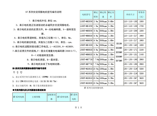
ST系列交流伺服电机型号编号说明1: 表示电机外径,单位:mm。
2:表示电机是正弦波驱动的永磁同步交流伺服电机。
3:表示电机安装的反馈元件,M—光电编码器,X—旋转变压器。
4:表示电机零速转矩,其值为三位数×0.1,单位:Nm。
5:表示电机额定转速,其值为二位数×100,单位:rpm。
6:表示电机适配的驱动器工作电压,L—AC220V,H—AC380V。
7:表示反馈元件的规格,F—复合式增量光电编码器(2500 C/T),R—1对极旋转变压器。
8:表示电机类型,B—基本型。
9:表示电机安装了失电制动器。
SD系列交流伺服驱动器型号编号说明1:表示采用空间矢量调制方式(SVPWM)的交流伺服驱动器2:表示IPM模块的额定电流(15/20/30/50/75A)3:表示功能代码(M:数字量及模拟量兼容)●交流伺服电机及伺服驱动器适配表ST系列电机主要参数适配驱动器ST系列电机ST系列电机电机型号额定转矩额定转速额定功率外形尺寸零售价(元)110ST-M02030 2 Nm3000rpm0.6KwSD15MSD20MNSD30MNSD50MNSD75MN110×110×1581500110ST-M04030 4 Nm3000rpm 1.2Kw110×110×1851700110ST-M05030 5 Nm3000rpm 1.5Kw110×110×2001800110ST-M06020 6 Nm2000rpm 1.2Kw110×110×2171900110ST-M06030 6 Nm3000rpm 1.6Kw110×110×2171900130ST-M04025 4 Nm2500rpm 1.0Kw130×130×1631800130ST-M05025 5 Nm2500rpm 1.3Kw130×130×1712100130ST-M06025 6 Nm2500rpm 1.5Kw130×130×1812400130ST-M077207.7 Nm2000rpm 1.6Kw130×130×1952900130ST-M077307.7 Nm3000rpm 2.4Kw130×130×1952900130ST-M1001510 Nm1500rpm 1.5Kw130×130×2193200130ST-M1002510 Nm2500rpm 2.6Kw130×130×2193200130ST-M1501515 Nm1500rpm 2.3Kw130×130×2673620130ST-M1502515 Nm2500rpm 3.8Kw130×130×2673620ST系列交流伺服电机110系列电机参数表电机型号110ST-M02030110ST-M04030110ST-M05030110ST-M06020110ST-M06030功率(Kw)0.6 1.2 1.5 1.2 1.6额定转矩(Nm)24566额定转速(Rpm)30003000300020003000额定电流(A)4.05.06.0 6.08.0转子惯0.33×10-30.650.82×10-3 1.0×10⁻³ 1.0×10⁻³量(Kgm2)×10-3机械时间常数(Ms)3.64 2.32 2.03 1.82 1.82编码器线数(C/T)2500C/T(A、B、Z、U、V、W)电机绕组插座绕组引线U V W地插座编号2341编码器插座信号5V0V A+A-B+B-Z+Z-U+U-V+V-W+W-地234758691013111412151插座编号失电制动器插座编号123电源24VDC(-15%~+10%)地基本参数工作电流:≤0.6A制动转矩:≥8Nm转动惯量:0.64×10⁻⁴Kgm2电机绝缘等级B使用环境环境温度:0~55℃湿度:小于90°(无结露)交流伺服电机及伺服驱动器安装尺寸ST系列交流伺服电机安装尺寸SD15M伺服驱动器安装尺寸SD20MN/30MN安装尺寸相关标签:电机, 伺服电机,相关产品WA-99UZWA-97TY步进电机的简单原印染专用步进电机直联型的步进电机相关新闻•2011电源管理及LED 精彩方案且看海默科技.............................................2011年03月18日•安森美半导体将在IIC-China 2011展出多种高能效方案...................................2011年03月18日•步进电机发热问题及对策.............................................................2011年03月18日•泽野驱动器2011隆重上市.............................................................2011年03月18日•Allegro推出汽车级可编程双极步进电动机驱动器IC......................................2011年03月18日•泽野电机34系列步进电机上市.........................................................2011年03月15日•步进电机14问.......................................................................2011年03月15日•用集成脉冲输出触发步进电机驱动器...................................................2011年03月15日•白山机电—DM系列产品荣登2011SIAF展................................................2011年03月15日•加快电机动力系统技术创新...........................................................2011年03月15日•交流伺服系统在许多性能方面都优于步进电机...........................................2011年03月09日•交流伺服电机传动技术实现了高精度的位置控制.........................................2011年03月09日•低速大扭矩交流伺服电机驱动单螺杆挤出机.............................................2011年03月09日•北仑伺服电机产业蓬勃兴起...........................................................2011年03月09日•伺服电机与变频电机的区别...........................................................2011年03月09日•哈电填补世界“百万级”水轮发电机通风技术空白.......................................2011年03月02日•日本电器零售商山田电机6月进津 (201)1年03月02日•联宜电机续发行0.5亿元短期融资券 (2011)年03月02日•对决:优派Pro8200vs三菱电机HC4000 (201)1年03月02日•三菱电机放电加工机技术交流会举办...................................................2011年03月02日•步进电机和交流伺服电机性能比较 (2011)年01月14日•伺服电机被步进脉冲控制的优点 (20)11年01月14日•三菱电梯创新成产业发展新动力 (20)11年01月14日•威力变频洗衣机智能洗涤更节能 (201)1年01月14日•西门子电气传动有限公司牵引电机及风力发电机扩大产能.................................2011年01月14日•交流伺服电机传动技术实现了高精度的位置控制.........................................2011年01月12日•伺服电机被步进脉冲控制的优点 (20)11年01月12日•2010年推出具有运动控制功能的伺服专用芯片...........................................2011年01月12日•伺服电机满足运动过程中精准的控制方式...............................................2011年01月12日•环形变压器的应用指南...............................................................2011年01月12日•雷赛:步进伺服专家运动控制先锋 (2011)年01月07日•交流伺服电机传动技术实现了高精度的位置控制.........................................2011年01月07日•瑞萨电子 32位MCU在伺服电机中的应用.................................................2011年01月07日•申力步进电机二相八线接线方法 (20)11年01月07日•如何用简单的方法调整两相步进电机通电后的转动方向..................................2011年01月05日•一种步进电机及其驱动器干扰问题解决措施.............................................2011年01月05日•第14届中国(国际)小电机展掠影 (20)11年01月05日•线切割机床驱动选型支招.............................................................2011年01月05日•步进马达市场总结分析及发展趋势 (2010)年12月31日•..................................................................2010年12月31日•运动控制系统简介...................................................................2010年12月31日•发现步进电机定位不准怎么办.........................................................2010年12月31日•何为驱动器的细分...................................................................2010年12月31日•步进电机使用时的注意事项...........................................................2010年12月29日•解决步进电机干拢问题的发法.........................................................2010年12月29日•关于步进电机的发热.................................................................2010年12月29日•关于步进电机和伺服电机的区别 (20)10年12月29日•乐创自动化推出三相混合式步进电机驱动器.............................................2010年12月29日•步进电机原理及使用说明.............................................................2010年12月22日•步进电机控制器的设计...............................................................2010年12月22日•一体化步进电机驱动器...............................................................2010年12月22日•作为机床通信中心的Sinumerik.......................................................2010年12月22日•全电动注塑机电控原理...............................................................2010年12月22日•步进电机的问题解答.................................................................2010年12月15日•申力步进电机二相八线接线方法 (20)10年12月15日•步进电机的种类和特点...............................................................2010年12月15日•新的步进电机控制器/驱动器简化步进电机系统设计......................................2010年12月15日•“株洲动力”创造世界高铁运营最高速.................................................2010年12月08日•三洋开始量产号称全球转换率最高 (2010)年12月08日•2010年中国电机工程学会年会在海口举行...............................................2010年12月08日•山社电机株式会社开拓中国市场 (20)10年11月24日•木工雕刻机中步进电机驱动器选型注意事项.............................................2010年11月24日•关于步进电机的发热.................................................................2010年11月24日•申力步进电机二相八线接线方法 (20)10年11月24日•步进电机的一些基本参数.............................................................2010年11月03日•反应式步进电机.....................................................................2010年11月03日•步进电机驱动器的故障分析...........................................................2010年11月01日•步进电机的最新技术发展.............................................................2010年10月21日60ST-M系列交流伺服电机技术参详绝缘电阻——500VDC 100MW Min绝缘强度——1500VAC 1Minute环境温度—— -20℃~ +50℃绝缘等级——B级60ST-M系列交流伺服电机优点1、无电刷和换向器,因此工作可靠,对维护和保养要求低。
伺服电机选型手册 (3)

伺服电机选型手册1. 引言伺服电机是一种能够精确控制运动位置、速度和力矩的电动机。
它通常由电机、编码器和伺服驱动器组成,可以在工业控制、自动化生产等领域中广泛应用。
本选型手册将为您介绍伺服电机的选型原则和方法,并为您提供一些建议,帮助您选择适合的伺服电机,以满足您的应用需求。
2. 选型原则在选择伺服电机时,我们应考虑以下几个原则:2.1 负载特性分析首先,我们需要分析应用的负载特性,包括负载的惯性、负载的运动模式(连续运动或间歇运动)、负载的最大运动速度和力矩等。
通过对负载特性的分析,可以确定所需的电机功率和扭矩。
2.2 控制精度要求控制精度是另一个重要考虑因素。
不同的应用对控制精度有不同的要求。
如果需要更高的控制精度,通常需要选择具有更高分辨率的编码器和更精确的驱动器。
2.3 环境条件环境条件也会影响伺服电机的选型。
例如,如果应用环境存在较高的温度或湿度,我们应选择具有较高的防护等级的伺服电机。
2.4 成本和可靠性最后,我们还需要考虑成本和可靠性因素。
根据应用需求和预算限制,选择合适的伺服电机,并确保其具有足够的可靠性,以避免故障和停机造成的损失。
3. 选型方法在选型伺服电机时,可以按照以下步骤进行:3.1 确定负载惯性和负载模式首先,确定应用的负载特性,包括负载的惯性和运动模式。
惯性可以通过负载的质量和尺寸计算得出。
运动模式可以根据应用的工作周期和停顿时间来确定。
3.2 计算所需的功率和扭矩根据负载的特性,计算所需的电机功率和扭矩。
功率计算公式如下:功率(W)= 扭矩(Nm) × 转速(rad/s)3.3 确定控制精度要求根据应用的控制精度要求,确定所需的编码器分辨率和驱动器性能。
3.4 选择合适的型号和规格根据以上计算结果和需求,选择合适的型号和规格的伺服电机。
可以参考厂商提供的技术手册和产品目录,查找符合要求的伺服电机型号。
3.5 考虑环境条件和成本要素在最终选择伺服电机之前,考虑应用环境条件和成本要素。
Cooper Bussmann 电机电路保护选型说明书
132©2005 Cooper Bussmann3. Circuit breakers must be periodically tested to verify they mechanical operate and electrically tested to verify they still are properly calibrated within specification.The circuit breaker manufacturers recommend this. Typically circuit breakers should be mechanically operated at least every year and electrically tested every 1 to 5 years, depending on the service conditions. Modern current-limiting fuses do not have to be maintained or electrically tested to verify they still will operate as intended. The terminations of both circuit breakers and fusible devices need to be periodically checked and maintained to prevent thermal damage. Plus fuse clips should be periodically inspected and if necessary maintained.4. After a circuit breaker interrupts a fault, it may not be suitable for further service.UL489, the product standard for molded case circuit breakers, only requires a circuit breaker to interrupt two short-circuit currents at its interrupting rating. Circuit breakers that are rated 100 amps or less do not have to operate after only one short circuit operation under “bus bar” short circuit conditions. If the fault current is high, circuit breaker manufacturers recommend that a circuit breaker shouldreceive a thorough inspection with replacement, if necessary. How does one know a circuit breaker’s service history or what level of fault current that a circuit breaker interrupts? With modern current-limiting fuses, if the fuse interrupts a fault, new factory calibrated fuses are installed in the circuit. The original level of superior short circuit protection can be there for the life of the motor circuit.5. After a fault, the electrician has to walk back to the storeroom to get new fuses;that is if spare fuses are not stored adjacent to the equipment. This does require some additional down time. However, if fuses opened under fault conditions, there is a fault condition that must be remedied. The electrician probably will be going back to the storeroom anyway for parts to repair the fault. If properly selected current-limiting fuses are used in the original circuit, the starter will not sustain any significant damage or loss of overload calibration.With circuit breaker protection on motor circuits, after a fault condition, it may be necessary to repair or replace the starter, so a trip to the storeroom may be necessary. And if the starter is not significantly damaged, it may still need to be tested to insure the let-through energy by the circuit breaker has notcaused the loss of starter overload calibration. Also, the circuit breaker needs to be evaluated for suitability before placing it back into service. Who is qualified for that evaluation? How much time will that take?In summary, resettability is not an important feature for motor branch circuit (short circuit) protection and resettability of the branch circuit protective device is not a benefit for motor circuits. As a matter of fact, resettability of the motor branch circuit overcurrent protective device may encourage an unsafe practice. The function of motor branch circuit protection is fault protection:short circuit and ground fault protection. Faults do not occur on a regular basis. But when a fault does occur, it is important to have the very best protection. The best motor branch circuit protection can be judged by(1) reliability - its ability to retain its calibration and speed of operation over its lifetime, (2) current-limiting protection -its ability to provide Type 2 “no damage”protection to the motor starter, and (3) safety - its ability to meet a facility’s safety needs. Modern current-limiting fuses are superior to circuit breakers for motor branch circuit protection.After a heavy fault on a motor branch circuit, you may need to (1) replace the fuses or (2) reset the circuit breaker and replace the starter (and maybe the circuit breaker, too).Motor Circuit Branch Circuit ProtectionIs Resettability of Value?。
Parker 旋钮式电机分类目录说明书

Index Rotary ActuatorsParker . . .PV Series Vane Actuators•8 model sizes• 2 standard rotations•7 to 1800 lb-in output torque at 100 PSIGSingle or double-vane actuators are permanentlylubricated for trouble-free service and low breakaway. Unique construction provides high torque in a compact, lightweight package. Options include stroke adjusters, bumpers, rear porting, fluorocarbon seals, and magnets for Hall effect or reed switches. Pressures to 150 PSIG.WR Series Wrist Rotate Units• 2 models•Adjustable rotation from 30° to 205°•15 and 65 lb-in output torque at 100 PSIGRugged actuators provide added features to allow use as a modular pick-and-place component or as a precision pneumatic rotary actuator. Features include hydraulic shock absorbers or polyurethane bumpers and optional plug-in style inductive proximity sensors.PRN Series Vane Rotary Actuators• 5 miniature and 4 standard models•Rotation angles 90°, 100°, 270° and 280°•Oscillating reference points of 40°, 45° and 90°•1.33 to 2355 in-lb torque at 100 PSIPRN Series single or double-vane actuators yield a high output torque to weight ratio. The unique vane design assures minimal leakage and stable low speed oscillation at low operating pres-sures. Foot or flange mounting is available. Reed and Hall effectswitches are optional.PTR SeriesRack & Pinion Actuators• 5 bore sizes from 1” to 3-1/4”• 5 standard rotations•39 to 2250 lb-in output torque at 100 PSIGRugged, reliable single or double-rack actuators provide superior performance with the broadest torque range in the industry.Proximity sensors, Hall effect and reed switches are available for position sensing. A wide choice of options for unmatchedapplication flexibility including three-position, anti-backlash and integral air/oil units are available. Pressures to 250 PSIG.HP SeriesRack & Pinion Actuators• 2 models• 3 standard rotations•4,500 and 10,000 lb-in output torque at 100 PSIGRugged, large-bore actuators provide reliability in heavy-duty applications. Steel racks and pinions and a full range of options. Pressures to 100 PSIG.XR SeriesRack & Pinion Actuators• 5 bore sizes from .56” to 2.00”•8 standard rotations• 6 to 236 lb-in output torque at 100 PSIGEconomical compact, high-performance actuators offer rugged internal components packaged in a precision, unitized aluminum housing. Numerous options include bumpers, cushions, shock absorbers, stroke adjusters, reed and Hall effect switches, flow controls and anti-backlash. Pressures to 150 PSIG.B671/F672 Actuators• 4 bore sizes from 1-1/2” to 5”•100 to 2500 lb-in output torque at 100 PSIRugged design provides equal torque in both directions throughout the range of rotation. Can be coupled to a Hydrocheck for smooth, controlled motion.Prelubricated. Pressures to 140 PSI.Torque RangeIntroduction100009000800070006000500040003500300025002000175015001250100090080070060050040030025020015010080604035302520151050HP10HP10HP4.5HP4.5PRN800D B6714B6714PTR322PTR322PV46D PRN800S PRN800SPV44D PTR321, B6713PTR321, B6713PRN300D PTR252PV46PTR252PV36D, PV42DPTR202, B6712PV44PTR202, B6712PV42D, PRN150D PTR251PTR251PV33D, PRN300SPV36, PRN300SPTR201PV42PTR201PTR152, XR20PTR152, XR20PRN150S PV33, PRN150SPV22D, PRN50DPTR151, B6711PTR151, B6711PRN30D XR15XR15PTR102PV22PTR102PRN50S PRN50S PRN30S PTR101, XR10PRN30SPTR101, XR10PV11D PRN20S PRN20SPV10D XR07XR07PRN10SPV11, PRN10SXR05PV10XR05PRN1S, PRN3S PRN1S, PRN3SNominal Torque at 100 PSIActuator Model,Rotation ≤ 95°Actuator Model,Rotation >100°Torque SelectionParker rotary actuators provide output torque up to 10,000 lb-in. The chart to the right shows the nominal torque output range of various actuator models at 100 PSI.Caution:This chart is intended as a guide only. Refer to actual product data in this catalog before specifying an actuator.Factors such as pressure rating, rotation, and actual torque output may be affected by specific product details and options.Output Torque,lb-inVaneVaneRack & PinionRack & PinionType VaneRack & PinionSeriesPRN PV WR XR PTR B671HP 90°/100° 195°/100° 1210°90°/100°90°90°90°Standard Rotations180° 2275°/280° 2180°/190°180°180°180°270°/280° 2270°/280°270°360°/370°360°360°360°Maximum Torque at 100 psi (lb-in)25401800652362000250010,000Maximum Air Pressure Rating (psi)100/140150150150250140100Shaft Bearing Type Ball or Radial Ball Radial Ball Radial Ball Bronze Bronze CompositeComposite BushingBushingBushingBushingBushingBushingNon-Lube Service •••••••Metric (M) or Imperial (I)M I II M, I I IHall Effect••C••Switch OptionsReed••C••CProximity sensor •C ••Double end••••Shaft OptionsFemale •••Preload keyway ••Special C CC C CCStroke adjust••••••Rotation Cushions ••••Options Bumpers •••••Shock absorbers••••Port Relocation ••••C•3-Position C•Air/Oil ••3Zero Backlash •••••Fluorocarbon Seals •••••Flange Mount •••Washdown C •C CClean RoomC•C•= Available from catalog C = Consult Factory Performance OverviewBasic performance features of the rotator product line are shown below.See catalog sections for greater detail and ordering information.1 Double vane 2Single vane 3Hydro-check optionFeaturesIntroductionDesign torqueDesign torque represents the maximum torque that an actua-tor must supply in an application. This maximum is the greater of the Demand Torque or the Cushion Torque. If the demand torque exceeds what the actuator can supply, the ac-tuator will either move too slowly or stall. If the cushion torque is too high, the actuator may be damaged by exces-sive pressure. Demand torque and cushion torque are de-fined below in terms of load, friction, and acceleration torque.Equations for calculating demand torque and cushion torque for some general applications are provided on the following pages.T - TorqueThe amount of turning effort exerted by a rotary actuator.T D - Demand TorqueThis is the torque required from the actuator to do the job and is the sum of the load torque, friction torque, and accel-eration torque, multiplied by an appropriate design factor.Design factors vary with the applications and the designers’knowledge.Equation 4-3)T T T T D f L=++αT L - Load torqueThis is the torque required to equal the weight or force of the load. For example, in Fig. 4-8a, the load torque is 563 N•M (5000 lb-in.); in Fig. 4-8b the load torque is zero; in Fig. 4-8c the load torque is 563 N•m (5000 lb-in.). The load torque term is intended to encompass all torque components that aren't included in the friction or acceleration terms.T f - Friction torqueThis is the torque required to overcome friction between any moving parts, especially bearing surfaces. In Fig. 4-8a, the friction torque is zero for the hanging load; in Fig. 4-8b the friction torque is 775 N•m (6880 lb-in) for the sliding load;in Fig. 4-8c the friction torque is zero for the clamp.Equation 4-4)T Wrf =µT a - Acceleration TorqueThis is the torque required to overcome the inertia of the load in order to provide a required acceleration or decelera-tion. In Fig. 4-8a the load is suspended motionless so there is no acceleration. In Fig. 4-8b, the load is accelerated from0 to some specified angular velocity. If the mass moment of inertia about the axis of rotation is I and the angular accel-eration is a, the acceleration torque is equal to Ia. In Fig. 4-8c there is no acceleration.Some values for mass moment of inertia are given in Table 4. Some useful equations for determining a are listed in Table 5. Equation 5 below shows the general equation for accel-eration torque.Equation 4-5)T C - Cushion TorqueThis is the torque that the actuator must apply to provide a required deceleration. This torque is generated by restricting the flow out of the actuator (meter-out) so as to create a back pressure which decelerates the load. This back pressure (de-celeration) often must overcome both the inertia of the load and the driving pressure (system pressure) from the pump.See applications.Equation 4-6)The friction torque T f reduces the torque the actuator must apply to stop the load. The load torque T L may add to, or subtract from the torque required from the actuator, depend-ing upon the orientation of the load torque. For example, a weight being swung upward would result in a load torque that is subtracted.Warning: Rapid deceleration can cause high pressure intensification at the outlet of the actuator. Always in-sure that cushion pressure does not exceed the manufacturer's pressure rating for the actuator.KE – Kinetic Energy (1/2 J m ω2)This is the amount of energy that a rotating load has. The rotator must be able to stop the load. All products have ki-netic energy rating tables. Choose the appropriate decelera-tion option (i.e., bumper, cushions, shock absorbers, etc.) that meets or exceeds the kinetic energy of the load.Calculating Torque Requirements IntroductionPages 8-10 excerpted from the Parker Hannifin Design Engineers Handbook.T α = I αT C = T α* +P r V– T f ±T L θDemand Torque Examples IntroductionMoments of Inertia Introduction11Parker Hannifin Corporation Actuator DivisionΘωmax=.035 ×tα=ωmax2Θ57.3α=ωmax( t ⁄ 2 )K.E.=1/2 J m ω2T a=α × J mDistance from pivot point to T f =W × U s ×center of external bearingsT L= Torque arm length × W L × cos (φ)to C.G. of loadWhere φ =Angle between torque arm andhorizontal plane( )BASIC VELOCITY, ACCELERATION, KINETIC ENERGY AND TORQUE EQUATIONSEquations below are based on triangular velocity profile.Where:Θ=Angle of Rotation (Degrees)t =Time to rotate through Θ (sec)ω=Angular velocity, radians/sec α=Angular accelerations (radians/sec 2)W L =Weight of load (lbf)T a =T orque to accelerate load (lb-in)U s =Coefficient of static frictionJ m *=Rotational mass moment of inertia (lb-in-sec 2)T f =T orque to overcome friction (lb-in)T L=T orque to overcome effects of gravity*Use "I" values from T able 4.( )( )Basic EquationsIntroductionCONVEYOR STOPCLAMPINGTENSIONING/SHOCK ABSORPTIONMIXINGCAMMINGFEEDINGCONVEYOR TRANSFEROPENING/CLOSING TURNTABLE/INDEXINGDIVERTING UNLOADING/DUMPINGDAMPER CONTROLVALVE ACTUATIONHARMONIC DRIVENotes14Parker Hannifin CorporationActuator Division。
PARKER派克MPE系列伺服电动机技术手册

options and reduced complexity.
70.8
Continuous Peak
8
• Eight models covering three
frame sizes of 40, 60 and 80 mm
62.0
• 1.4 to 31.3 in-lbs continuous
MPE080
phone: 800.358.9068 / 707.584.7558 fax: 707.584.8015 email: emn_support@
0 0
1000
2000
3000
4000
0 5000
Speed RPM
MPE Common Specifications
1.2
0.26 2.3
Rated Shaft Output Power 1, 2, 3, 4 Current at Rated Speed 1, 2, 3, 4 Voltage Constant 4. 7 Torque Constant 4, 7 Resistance 4, 9
Pout Ir Ke
Tr
in-lb
6.0
10.6
Rated Shaft Output Power 1, 2, 3, 4 Current at Rated Speed 1, 2, 3, 4 Voltage Constant 4. 7 Torque Constant 4, 7 Resistance 4, 9
Pout Ir Ke
Arms Vrms/krpm Nm/Arms
ohm
Rated Shaft Output Power 1, 2, 3, 4 Current at Rated Speed 1, 2, 3, 4 Voltage Constant 4. 7 Torque Constant 4, 7 Resistance 4, 9
Parker Pneumatic产品选择指南说明书
Parker Hannifin Corporation Pneumatic Division Richland, Michigan/pneumaticsB341Parker Pneumatic1 Flying leads are2 meters in length 2 Flying Leads are 1.5 meters in length3 Flying leads are 1 meter in lengthBore size 3m flying 10m flying 8mm quickconnect 12mm quick Sensor Bracket Selection GuideNote: See page B354 for Weld Immune Sensors.* See page B355 for cord sets.Parker Hannifin Corporation Pneumatic Division Richland, Michigan/pneumaticsB346Parker PneumaticP8S Drop-in SensorsP8S Right Angle Solid State SensorsP8S Right Angle Reed Sensors213Wiring PNP sensors NPN sensorsWiring connectionWiring connectionPin Wire Function1Brown Operating voltage (+VDC)2Black Output signal (N.O.)3Blue-VDCPin Wire Function1Brown Operating voltage (+V)3Black Not used2BlueOutput signal (-V or Ground)SpecificationsType2-wire reed Output function Normally openOutput voltage 10 - 110* VAC, 10 - 30 VDC Continuous current ≤ 100 mA Response sensitivity 30 Gauss min.Switching frequency 400 Hz Voltage drop ≤ 3 VRipple≤ 10% of operating voltage Time delay (24v)Approx. 20 ms Hysteresis ≤ 1.0 mm Repeatability ≤ 0.2 mmEMCEN 60 947-5-2Reverse polarity protection Yes Enclosure ratingIP 67Shock and vibration stress 30g, 11ms, 10 to 55 Hz, 1 mm Ambient temperature range -25°C to +75°C (-13°F to 167°F)Housing material PA 12, black Connector cable PVCConnectorPUR cable w/8 mm connector* 8Mm connector rated for 50 vac max.SpecificationsTypeElectronic Output function Normally open Switching output PNP/NPN Operating voltage 10 - 30VDC Continuous current ≤ 150 mAResponse sensitivity 30 Gauss min.Switching frequency 5kHz Power consumption 15 mA Voltage drop ≤ 2 VDCRipple≤ 10% of operating voltage Delay time (24v)Approx. 20 ms Time delay before availability ≤ 2 ms Hysteresis ≤ 1.5 mm Repeatability ≤ 0.2 mmEMCEN 60 947-5-2Short-circuit protectionYes Power-up pulse suppression Yes Reverse polarity protection YesEnclosure ratingIP 67 DIN 40050Shock and vibration stress 30g, 11ms, 10 to 55 Hz, 1 mm Ambient temperature range -25°C to +75°C (-13°F to 167°F)Housing material PA 12, black Connector cablePVCConnector PUR cable w/8 mm connector.13Solid State Reed。
伺服电机选型的原则和注意事项
伺服电机选型的原则和注意事项为了满足机械设备对高精度、快速响应的要求,伺服电机应有较小的转动惯量和大的堵转转矩,并具有尽可能小的时间常数和启动电压,还应具有较长时间的过载能力,以满足低速大转矩的要求,能够承受频繁启动、制动和正、反转,如果盲目地选择大规格的电机,不仅增加成本,也会使得设计设备的体积增大,结构不紧凑,因此选择电机时应充分考虑各方面的要求,以便充分发挥伺服电机的工作性能;下面介绍伺服电机的选型原则和注意事项。
选用伺服电机型号的步骤1、明确负载机构的运动条件要求,即加/减速的快慢、运动速度、机构的重量、机构的运动方式等。
2、依据运行条件要求选用合适的负载惯最计算公式,计算出机构的负载惯量。
3、依据负载惯量与电机惯量选出适当的假选定电机规格。
4、结合初选的电机惯量与负载惯量,计算出加速转矩及减速转矩。
5、依据负载重量、配置方式、摩擦系数、运行效率计算出负载转矩。
6、初选电机的最大输出转矩必须大于加速转矩加负载转矩;如果不符合条件,必须选用其他型号计算验证直至符合要求。
7、依据负载转矩、加速转矩、减速转矩及保持转矩,计算出连续瞬时转矩。
8、初选电机的额定转矩必须大于连续瞬时转矩,如果不符合条件,必须选用其他型号计算验证直至符合要求。
9、完成选定。
伺服电机的选型计算方法1、转速和编码器分辨率的确认。
2、电机轴上负载力矩的折算和加减速力矩的计算。
3、计算负载惯量,惯量的匹配,安川伺服电机为例,部分产品惯量匹配可达50倍,但实际越小越好,这样对精度和响应速度好。
4、再生电阻的计算和选择,对于伺服,一般2kw以上,要外配置。
5、电缆选择,编码器电缆双绞屏蔽的,对于安川伺服等日系产品绝对值编码器是6芯,增量式是4芯。
以上的选择方法只考虑到电机的动力问题,对于直线运动用速度,加速度和所需外力表示,对于旋转运动用角速度,角加速度和所需扭矩表示,它们均可以表示为时间的函数,与其他因素无关。
很显然。
电机的最大功率P电机,最大应大于工作负载所需的峰值功率P峰值,但仅仅如此是不够的,物理意义上的功率包含扭矩和速度两部分,但在实际的传动机构中它们是受限制的。
- 1、下载文档前请自行甄别文档内容的完整性,平台不提供额外的编辑、内容补充、找答案等附加服务。
- 2、"仅部分预览"的文档,不可在线预览部分如存在完整性等问题,可反馈申请退款(可完整预览的文档不适用该条件!)。
- 3、如文档侵犯您的权益,请联系客服反馈,我们会尽快为您处理(人工客服工作时间:9:00-18:30)。
High-Torque Design, Compact Package
Parker’s SMN series of rotary servo motors combines a high-performance segmented stator design with competitive pricing for today’s demanding servo applications. The modern eight-pole segmented stator architecture produces extremely high torque values for a given motor volume. The SMN motor family is offered in frame sizes ranging from 60 mm to 142 mm and is available with resolver, quadrature encoder or high-resolution SinCos feedback devices.SMN Motor Features
• High performance per dollar
• High torque density package
• 1.4 – 14.5 N-m continuous torque range
• Brushless construction
• Resolver, encoder or SinCos (absolute) feedback • Five frame sizes from 60 mm to 142 mm
• IP64 standard
• IP65 option
Motor Part Numbering System
Series
SMN -SMN Family
Frame
060 - 60mm
082 - 82mm
100 - 100mm
115 - 115mm
142 - 142mm
Stack
2
Winding
P
Q
S
T
V
Z
Feedback
Type
Feedback
Resolution
41 - Resolver, single speed
2F - Quadrature encoder,
2048 line
5D - SinCos w/ Hiperface™
absolute encoder (Stegmann)
Shaft
K - Keyway
Connector
P - PS style
Options
N - None
B - Holding
brake
V - IP65 (shaft
seal)
1000200030004000500060007000
1000200030004000500060007000
1020304050
1000200030004000500060007000
1.13
2.26
3.39
4.52
5.650
1.13
2.26
3.39
4.52
5.650
100200300400500
100200300400500
11.3
22.633.945.256.50
11.3
22.633.945.256.5SMN0602T
Speed (RPM)T o r q u e (i n -l b )
Torque (Nm)
050100150200250300
5.6511.317.022.628.333.9
SMN1152T
T o r q u e (i n -l b )
Torque (Nm)
SMN1422S
Speed (RPM)
T o r q u e (i n -l b )
Torque (Nm)
SMN1422P
T o r q u e (i n -l b )
Torque (Nm)
1020304050
1000200030004000500060007000
SMN0602Z
Speed (RPM)T o r q u e (i n -l b )
Torque (Nm)
20406080100120
2.264.526.789.0411.31
3.7SMN0822S
Speed (RPM)
T o r q u e (i n -l b )
Torque (Nm)
050100150200250300350
5.6511.317.022.628.333.939.6
50100150200
50100150200
5.6511.317.022.6
5.6511.317.022.6
SMN1152Q
Speed (RPM)Speed (RPM)Speed (RPM)
T o r q u e (i n -l b )
Torque (Nm)
20406080100
0100020003000400050006000700001000200030004000500060007000
1000200030004000500060007000
1000200030004000500060007000
1000200030004000500060007000
1000200030004000500060007000
2.26
4.526.781.0411.3SMN0822V
Speed (RPM)T o r q u e (i n -l b )
Torque (Nm)
SMN1002S
Speed (RPM)
T o r q u e (i n -l b )
Torque (Nm)
SMN1002P
Speed (RPM)T o r q u e (i n -l b )
Torque (Nm)
Peak (120V)
Peak (240V)
Peak (460V)
Continuous
Motor Speed-Torque Performance Curves
1 @ 25˚ C ambient motor connected to a 10”x10”x1/4” aluminum mounting plate; @ 40˚ C ambient, derate phase currents and torques by 7%.
2 For higher-speed operation, please call the factory.
3 Measured line to line, +/- 10%.
4 Value is measured peak of sine wave.
5 +/- 30%, line to line, inductance bridge measurement @ 1Khz.
6 Initial winding temperature mut be 60˚ C or less before peak
7 Direct current through a pair of motor phases of a trapezoidally (six state) commutated motor.
8 Peak of sinusoidal current in any phase for a sinusoidally
commutated motor.
9 Total motor torque per peak of the sinusoidal amps measured in any phase, +/- 10%.
10 Maximum time duration with 2 times (or 3 times) rated current applied with initial winding temperature at 60˚ C.
Dimensional SMN Motors SMNxx
SMN0602 with Sin/Cos Encoder Option - 5D。