硬密封蝶阀使用维修手册
使用说明书-蝶阀(D343H)
6 该阀门单向密封、90°旋转,0°全关,90°全开,观察阀门 的启闭位置是否与此相附。并检查有无卡阻现象。
3. 针为开,操作时注意观察位置指 针或指示盘刻度;
5. 阀门在使用中遇到故障时应及时查明原因,及时排除,不得敲 砸、强行启闭;
六、主要零部件的材料及采用的标准
(1) 支架材料:WCB,采用标准:GB12229 (2) 填料压盖材料:WCB,采用标准:GB12229 (3) 密封填料材料:柔性石墨,采用标准:GB/T6620 (4) 上轴套:自润滑复合轴套 (5) 阀体材料:WCB,采用标准:GB12229 (6) 压板材料:Q235,采用标准:GB700-88 (7) 蝶板材料:WCB,采用标准:GB12229 (8) 阀轴材料:2Cr13,采用标准:GB1220 (9) 蝶板密封圈:304+石墨复合板 (10) 阀体密封面材料:堆焊不锈钢 D507 (11) 下轴套:自润滑复合轴套
1
PDF 文件使用 "pdfFactory Pro" 试用版本创建
二、主要性能规范
公称压力 PN(Mpa)
强度试验 MPa
密封试验 MPa
适用温度 (℃)
适用介质
1.0
1.5
1.1
水、蒸气、煤气、
1.6
2.4
1.76
≤380℃ 油品、热空气、
2.5
3.8
2.75
腐蚀性介质等
四、连接方式及其结构长度
蝶阀的连接方式为法兰连接, 其法兰的连接尺寸符合 GB/T9113.1-2000 标准要求。
蝶阀的结构长度符合 GB/T12221-2005 标准要求。
五、蝶阀的检验与试验
喜凯斯不锈钢蝶阀安装维护指南说明书

D I S C O N T I N UE DKEYSTONE BUTTERFLY VALVES FIGURE 55INSTALLATION AND MAINTENANCE INSTRUCTIONS1 STORAGE AND HANDLING1.1 ProtectionKeystone butterfly valves are delivered with protection in accordance with the Keystone Engineering Instructions, to protect the valve seats and disc from damage. Wrapping and/or covers should be left in place until immediately before fitting to the pipe.1.2 StorageWhen valves are to be stored for some time (2 months or more) before being fitted, storage should be in the original delivery crates or cases.1.2.1 Storage conditions The valves should be stored off theground in a clean, dry indoor area. Protect the valve from temperatureand humidity extremes, and exposure to excessive dust, moisture, vibration, deformations, sunlight and ozone.Please read these instructions carefully Hazard potentials:• disregarding of instructions • improper use of product• insufficiently qualified personnel Valve application to be within thepressure/temperature limits indicated in the P/T diagram.Essential points and functions of the valve should be inspected on a regular basis.When the valve is used in an end-of-line function, PED Cat-I applications are allowed only. For other categories, contact factory. 1.3 Handling1.3.1 Packed valves Lifting and handling of the packed valves incrates should be carried out by appropriate lifting equipment. If a fork lift truck is used, appropriate fork hitches are required. The lifting and handling of packed valves incases will be carried out in the lifting points. The transportation of all packed materialshould be carried out safely andaccording the local safety regulations.1.3.2 Unpacked valves The lifting and the handling of thesevalves has to be carried out by using appropriate means and by respecting the carrying limits. The handling must, preferably, be carried out on pallets, protecting the machined surfaces and seat to avoid damage. When lifting the large dimension valves,the sling and the hooking of the load must be carried out by using the appropriate tools (brackets, hook, fasteners) and load balancing tools in order to prevent the valves from falling or moving during the lifting and handling. The valve may be lifted only by slingsattached to the flange holes or valve body; never to the actuator or the valve opening.Before installation these instructions must be fully read and understoodRecommendations1. Temperature: storage temperature below 25°C, above 0°C preferable below 15°C.2. Humidity: storage conditions should be such that condensation does not occur, store in a dry environment. Maximal 50% relative humidity.3. Light: valve rubbers should be protected from light, in particular direct sunlight or strong artificial light with high ultra violet.4. Ozone: storage rooms should notcontain any equipment generating ozone. E.g. lamps, electric motors.IMPORTANTBefore valves are being installed or used the following actions are recommended.1. Valves/parts have to be inspected and thoroughly cleaned if required.2. Rubber parts need to be greased with silicone grease if not present anymore.3. All surfaces in contact with seats have to be thoroughly cleaned and greased with silicone grease if stored for more than 5 months.D I S C O N T I 2.1 Valve inspection1. Carefully remove the valve from theshipping package (box or pallet) avoiding any damage to the valve or, in case of automated valves, to the electric or pneumatic/hydraulic actuator or instrumentation.2. Confirm that the materials of construction listed on the valve nameplate areappropriate for the service intended and are as specified.3. It is not allowed to use third party spareparts. In case of third party spare parts, safe operation is not guaranteed.2 INSTALLATIONWARNINGFor safety reasons, it is important to take the following precautions before you start work on the valve:1. Personnel making any adjustments to the valves should utilize suitable equipment. All required personal protection means should be worn.2. The line must be depressurized before installing the valve.3. Personnel trained in all aspects of manual and mechanical handling techniques only must carry out handling of the valves.4. Misuse of the valve is not allowed. Forexample: the valve, handles, actuators or other parts may not be used as ‘climbing tools’.5. Ensure that valve pressure/temperaturelimitations marked on the identification tag are within the service conditions. The trim number on the valve’s tagplate identifies the valvematerials. See Product Manual for valve specific P/T diagram and trim number definition.6. Ensure that valve materials are compatible with the pipeline fluid.2.2 Flange and pipe compatibilityCheck matching of flange drilling pattern of valve and pipe flange before assembly.Flanges have to meet the following requirements:- The face inside diameter should be: D min.: T he valve Q-dimension + adequatedisc clearance.D max.: T he inside diameter (ID) of standardpipe for the nominal size ISO 4200.- If the flange (or pipe) is provided with a raised face, the diameter of this shall be at least 10 mm larger than the YY-dimension of the valve.The use of the flange-gaskets is not allowed since it might damage the valve.The Keystone seat-face design eliminates the need for the gaskets.Use flange bolting in agreement with appropriate standard.Do not use flange gaskets!D I S C O N T I N UE D2.3 Valve installationThe valves are bi-directional and may be fitted in either direction relative to the flow. The valve will control flow equally in either direction. The recommended installation position is shaft horizontal and the lower disc edge opening down-stream. (Especially for slurry service and media with a tendency for sedimentation). For optimum valve control and smooth performance, it is recommended to have a 10 to 20 pipediameters of straight run inlet piping and 3 to 5 pipe diameters straight outlet piping. A valve is no crow-bar. Do not use the valve to spread the flanges. Seat damage might be the result.2.3.1 Existing system (see sketch) 1. C heck whether the flange distancemeets the valve face-to-facedimensions. Spread with adequate tooling the flanges for easy insertion of the valve.2. C lose the valve so far, that the discedge is at least 10 mm within the body.3. I nsert the valve between the flanges,center the valve body and insert all flange bolts.4. M aintain the valve flange alignmentwhile gradually removing the flange-spreaders and tighten the flange-bolts hand tight.5. S lowly open and close the valve tocheck for adequate disc clearance.6. C ross-tighten all bolting to the propertorque.2.3.2 New system (see sketch) 1. W ith the disc in near-closed positioncenter each mating flange with the valve body. Fix the body with some flange-bolts and tighten the bolts.2. U se the flange-valve-flange assemblyfor fit-up and centering to the pipe.3. Tack-weld the flanges to the pipe.4. R emove the bolting and the valve frombetween the flanges.NOTES- The valve can be installed in the pipe-line either with or without the actuator mounted on top of the valve. Make sure that you can turn the disc cautious so you can feel a mismatch resulting from a disc touching the adjacent piping.- Do not use the valve as a support of the pipe line construction.- Adjacent piping must be positioned so that minimal piping stresses are transmitted to the valve flanges during or after installation.- Handling and lifting of the valves during installation MUST be performed following the same instructions described in previous paragraph ‘1.3 Handling’.IMPORTANTMating flange faces should be in good condition and free of dirt and/or inclusions. Both pipe insides to be well cleaned.IMPORTANTD o not finish-weld the flanges to the pipe with the valve bolted between the flanges as this will result in serious heat-damage to the seat. 5. F inish-weld the flanges to the pipe and allow the flanges to cool completely.6. I nstall the valve now according to the procedure for installing in existing systems.D I S EXISTING SYSTEMNEW SYSTEM3. C lose the valve clockwise, return to open position and cross-tighten all bolting. 3. R emove the valve and finish weld. Install the valve according to the procedure in the left column.2.4 Valve verificationCheck the operation of the valve by operating it to ‘full open’ and ‘full close’. To verify the valve operation, the disc position indicator on the actuator or the handle should rotate between the ‘full open’ and ‘full close’ indicators on the actuator or throttle plate. Generally the valve disc travels clockwise to close.2.5 Sources of possible dangerThis section contains some examples of possible foreseen danger sources.2.5.1 Mechanical A. W hen manual operators are used,available space should be checked in order to avoid hands being clamped.B. M echanical sparks caused on impactof valve and e.g. tooling, are a potential source of ignition of surrounding atmosphere.2.5.2 Electrical If static charges or stray electricalcurrents can initiate explosions, the valve should be grounded to earth.2.5.3 Thermal A. I f the valve is used in applicationswith a fluid temperature above 40°C the outside of the body might be hot. Sufficient measurements should be taken to avoid burning. A manual operated valve should be opened and closed with sufficient protection for the personnel operating the valve. For example: protecting gloves.B. H ot surfaces can be a potential sourceof ignition of the environment.2.5.4 Operational Closing a valve too fast may result inwaterhammer in the upstream part of the pipeline. Waterhammer results in excessive stresses in the valve’s body and will cause severe damage. Waterhammer should be avoided in all circumstances. Due to differential pressure across thevalve disc, butterfly valves have the tendency to be closed by the flow. Take care when unlatching the valve operating mechanism.D I S C O N T I N UE D3 MAINTENANCEThe Keystone butterfly valve figure 55 isdesigned to require a minimum of maintenance.WARNINGDepressurize and, if necessary in case ofdangerous fluids, drain the line and flush with appropriate cleaning fluid before starting any maintenance. Failure to do so may cause serious personal injury and/or equipment damage.Before disassembling the valve ensure the valve has been decontaminated correctly from any harmful gasses or liquids and that it is within a safe temperature range for handling.Personnel making any adjustments to the valves should utilize suitable equipment. All required personal protection means should be worn.Only personnel trained in all aspects of manual and mechanical handling techniques must carry out handling of all valves.3.1 Routine maintenanceRoutine maintenance or lubrication is not required other than periodic inspection to ensure satisfactory operation and sealing.3.2 Removing the valve1. Turn the disc to nearly closed position. (The disc is in line with the parallel flats or keyway in the stem).2. Loosen all flange bolts and remove the bolt s.3. Spread the flanges with adequate tooling, and remove the valve.3.3 Valve disassembly1. Turn the disc to almost open position.2. Remove actuator.3. Remove the disc screw(s) with the O-ring(s).4. Pull the shaft out of the body (shaft valve sizes DN 350 - 600 contain a tapped hole for mounting lifting eyebolt).5. Remove the disc by pulling or ‘rolling’ out of the seat bore.6. Remove circlip and pull the plug, containing an O-ring, out of the body.7. Remove the O-ring from the plug.8. Remove the dirt scraper and bushing from the body.2.6 TROUBLESHOOTING GUIDESymptomPossible cause ResolutionValve would not rotate Actuator has failedReplace or repairValve packed with debris Flush or clean valve to remove debris Valve leakingValve not fully closed Close valveDebris trapped in valve Cycle and flush (with valve open) to remove debris Seat is damagedReplace valveJerky operationDebris trapped in valveCycle and flush (with valve open) to remove debris Air supply actuator inadequate Increase air supply pressure and/or volume3.4 Valve assembly 1. Clean all parts.2. Insert the bushing.3. Insert the shaft with sufficient (silicone)grease so far that it protrudes approximately 10 mm into the inside bore of the seat. Install the disc, with the disc screw holes toward the actuator flange, by inserting the disc in the seat with the shaft bore on the topside against the shaft, leaving the bottom part of the disc just outside the seat. Push the bottom part of the disc in place with a twisting motion.4. Insert the shaft completely using a rotating pressure on the shaft, and a rotating motion on the disc. Pay special attention in order that the seat is not damaged due to any misalignment of stem holes.5. Align the counter-drilled position of the stem screw holes. Place the O-ring(s) on the disc screw(s). Install the disc screw(s) and tighten securely.6. Place the O-ring onto the plug.Place the plug into the body and position it with a circlip.7. Assemble the dirt scraper.8. Mount the actuator.3.5 Re-installing the valve See paragraph 2.3.1.D I S C Parts list 1.Body 2.Disc 3.Seat 4.Shaft5.Disc screw6.O-ring7.Bushing8.Plug9.O-ring 10.Circlip11.Dirt scraperonlyVCIOM-00756-EN © 2017, 2019 Emerson Electric Co. All rights reserved 01/19. Keystone is a mark owned by one of the companies in the Emerson Automation Solutionsbusiness unit of Emerson Electric Co. The Emerson logo is a trademark and service mark of Emerson Electric Co. All other marks are the property of their prospective owners.The contents of this publication are presented for informational purposes only, and while every effort has been made to ensure their accuracy, they are not to be construed as warranties or guarantees, express or implied, regarding the products or services described herein or their use or applicability. All sales are governed by our terms and conditions, which are available upon request. We reserve the right to modify or improve the designs or specifications of such products at any time without notice.Emerson Electric Co. does not assume responsibility for the selection, use or maintenance of any product. Responsibility for proper selection, use and maintenance of any Emerson Electric Co. product remains solely with the /FinalControl。
蝶阀安装及维修手册1
蝶阀安装及维修手册1 浏览:28[蝶阀安装及维修手册1] -> 返回首页>>蝶阀安装及维修手册Butterfly Valve Installation & Maintenance Manual安装说明Installation Description协羽蝶阀是设计用于管路系统连接,两个法兰间的连接或一个法兰间的连接或一个法兰间的连已经固定的管路系统。
蝶阀的把手(或齿轮箱)是可以反转或正转180度操作。
协羽的蝶阀安用方形螺丝,螺母及华司所组成。
Hsieh Yu butterfly valve is designed for pipeline system connection between two flanges or wi for connection with the pipeline system of which one side has been fixed. The handle (or butterfly valve can be rotated backward or forward for 180 degrees. Hsieh Yu butterfly valv for installation with square screw, nut and washer.标准形蝶阀安装手册Standard butterfly valve installation manual第一步骤Step 1将管路上的法兰部分,要求及安装步在本手册里。
【注意】管路上的紶兰将要求精确的对正螺丝孔位置及想要的阀门位置。
Installation procedures, requirement for the flanges in the pipeline system have been stated in this Manual.[Note]: I required that flanges on the pipeline have to be aligned accurately with the screw holes and the desired position of t valves.第二步骤Step 2检查管路两法兰的螺丝孔的是否有对正及预留的间隙。
蝶阀的运行与护手册

设备运行维护手册河南中岳阀门制造有限公司2010年1月21日蝶阀的运行与维护手册蝶阀的运行注意事项:1、蝶阀的运行过程中必须三天内要进行一次全开全闭操作,否则阀门会出现锈死现象。
2、在关闭过程中如果发生关闭不严时,应该将阀门再次完全打开,利用管道的水压进行冲刷管道的内壁杂质后,再次关闭阀门。
3、关闭或打开阀门的过程中不能利用加长杆或过大力量进行操作。
4、带有旁通阀的蝶阀,开启前应先打开旁通阀。
5、应按蝶阀制造厂的安装说明书进行安装,重量重的蝶阀,应设置牢固的基础。
6、尽量过滤管道内的杂质,预防蝶阀关闭时挤坏密封面,造成无法完全关闭的现象。
蝶阀的使用维护注意事项:1、蝶阀的开度与流量之间的关系,基本上呈线性比例变化。
如果用于控制流量,其流量特性与配管的流阻也有密切关系,如两条管道安装阀门口径、形式等全相同,而管道损失系数不同,阀门的流量差别也会很大。
2、如果阀门处于节流幅度较大状态,阀板的背面容易发生气蚀,有损坏阀门的可能,一般均在大于15°外使用。
3、蝶阀处于中开度时,阀体与蝶板前端形成的开口形状以阀轴为中心,两侧形成完成不同的状态,一侧的蝶板前端顺水流方向而动,另一侧逆水流方向而动,因此,一侧阀体与阀板形成似喷嘴形开口,另一侧类似节流孔形开口,喷嘴侧比节流侧流速快的多,而节流侧阀门下面会产生负压,往往会出现橡胶密封件脱落。
4、蝶阀操作力矩,因开度及阀门启闭方向不同其值各异,卧式蝶阀,特别是大口径阀,由于水深,阀轴上、下水头差所产生的力矩也不容忽视。
另外,阀门进口侧装置弯头时,形成偏流,力矩会有增加。
阀门处于中间开度时,由于水流动力矩起作用,操作机构需要自锁。
微阻缓闭止回阀运行维护手册微阻缓闭止回阀产品属于免操作产品,运行过程中它可以自动打开,自动关闭,在运行过程中应经常检查油缸的使用情况,是否需要添加液压油,半年或一年后应关闭管道打开阀门检查胶圈的使用情况,必要时清除沉积在阀板周围的污垢。
3英寸蝶阀维护手册说明书
3” BUTTERFLY VALVEMAINTENANCE MANUAL //MM008 REV01 - 27.08.13IMPORTANT:PLEASE READ THE INSTRUCTIONS IN FULL PRIOR TO COMMENCING WORK ON THE VALVE. Manual Contents∙Valve Identification.∙General Assembly Dismantling.∙Valve Dismantling.∙Valve Re-assembly.∙General Assembly Re-assembly.Tooling Required∙13mm A/F Spanner.∙ 2 x 17mm A/F Spanner.∙ 2 x 19mm A/F Spanner.∙ 2 x 24mm A/F Spanner.∙3mm A/F Allen Key.∙6mm A/F Allen Key.∙Torque Wrench.∙Soft Mallet.∙Nut Retainer.∙Small Sharp Knife.∙‘O’ Ring Expanders and Resizers.∙Stuffing Plate Tube.BEFORE ATTEMPTING DISASSEMBLY OR REMOVAL OF ANY FORT VALE COMPONENT, ALWAYS DEPRESSURIZE AND DRAIN ANY PIPING SYSTEMS.Prior to commencing any remedial work :Prior to handling the valve,ascertain the last product carried and ensure that the valve has been correctly decontaminated. Obtain a Material Safety Data Sheet for the last product carried and observe all the Health and Safety advice, particularly with regards to P .P .E. (Personal Protection Equipment)personnel Servicing of valves should be conducted by a “Qualified Person”The term “qualified person” relates to a person familiar with the installation, assembly, operation, applications andlimitations of the component. The person should have the qualifications corresponding to their responsibilities, such as instruction and awareness to comply with all operational, regional and in-company regulations and requirements.Limitations of use/Mis-usePlease observe the maximum allowable working pressure and the minimum/maximum allowable temperature range and ensure that the valve is not operated outside these limitations. Use/operation outside these limits is at the risk of the user and Fort Vale shall bear no responsibility for such actions.ServicingFort Vale components are manufactured for longevity under normal and compatible working conditions. It is the responsibility of the user to take into account the working conditions of the valve and to implement a regular serviceschedule based upon individual circumstances. In addition, a thorough visual inspection of the valve should be made at regular intervals to check for correct operation and signs of corrosion. It must be noted that working at extremes of temperature and/or pressure will reduce the operational life of the valve between services.AFTER ANY REMEDIAL WORK, ENSURE THAT THE VALVE IS LEAK TESTED PRIOR TO RETURNING TO SERVICE.During service or testing, if any problem arises that cannot be resolved with the use of this Maintenance Manual, please contact Fort Vale for further advice and assistance.Risk assessment and hazard assessmentFort Vale recommends a full and comprehensive risk and hazard assessment in accordance with national or locallegislation prior to servicing a valve. Not all service environments are the same and basic instructions may need to be incorporated into the safe procedures for use of the end user. See examples below:- Correct use of personal protection equipment when working with compressed gases- Correct use of personal protection equipment when working with low temperature components- Correct use of personal protection equipment when working with heavy components and the use of lifting equipment - Training and competence ofconducting pressure testingThis page is intentionally blank.A .B Series 3” Butterfly Valve (Clamped and Composite).B. A Series 3” Butterfly Valve (Clamped, Flanged and Composite).C. Original 3” Butterfly Valve (Clamped, Flanged and Composite).Butterfly ValveValve Identification.THIS DRAWING IS AN UNCONTROLLED COPY AND AS SUCH WILL NOT BE AUTOMATICALLY UPDATED Printed by Gerard_van_der_bok on 08 June 2017 at 09:55:32 GMT EXPIRES ON 08 July 2017A . 3” Clamped Butterfly Valves/Footvalve Assemblies. B. 3” Flanges Butterfly Valves/Footvalve Assemblies. C. 3” Composite Butterfly Valves/Footvalve Assemblies.Butterfly ValveGeneral Assembly Breakdown.THIS DRAWING IS AN UNCONTROLLED COPY AND AS SUCH WILL NOT BE AUTOMATICALLY UPDATED Printed by Gerard_van_der_bok on 08 June 2017 at 09:55:32 GMT EXPIRES ON 08 July 2017A. Basic Butterfly Valve Design.B. Valve DismantlingButterfly Valve Valve Dismantling.THIS DRAWING IS AN UNCONTROLLED COPY AND AS SUCH WILL NOT BE AUTOMATICALLY UPDATED Printed by Gerard_van_der_bok on 08 June 2017 at 09:55:32 GMT EXPIRES ON 08 July 2017A. Important Surfaces.B. Spindle Seals.C. Valve Re-assembly.D. Replacing Main Seal and Aligning Closure Plate.E. Pre A Series TIR.Butterfly ValveValve Re-assembly.THIS DRAWING IS AN UNCONTROLLED COPY AND AS SUCH WILL NOT BE AUTOMATICALLY UPDATED Printed by Gerard_van_der_bok on 08 June 2017 at 09:55:32 GMT EXPIRES ON 08 July 2017A. 3” B Series Clamped Butterfly Valves/Footvalves Assemblies.B. 3” A Series and Original Clamped Butterfly Valves/Footvalves Assemblies.C. 3” Flanged Butterfly Valves/Footvalves and Top Discharge Assemblies.D. 3” Composite Butterfly Valves/Footvalves Assemblies.Butterfly ValveGeneral Assembly Re-assembly.THIS DRAWING IS AN UNCONTROLLED COPY AND AS SUCH WILL NOT BE AUTOMATICALLY UPDATED Printed by Gerard_van_der_bok on 08 June 2017 at 09:55:32 GMT EXPIRES ON 08 July 2017This page is intentionally blank.All goods supplied will be subject to Fort Vale Engineering Ltd Terms and Conditions of Sale (Ref. FV4) which are available upon request, or may be viewed at .Please note that this brochure and the contents herein remain the property of Fort Vale Engineering Limited.This brochure may not be copied or reproduced, or the information contained herein divulged to any third party without the prior written permission of Fort Vale Engineering Limited.Repair/refurbishment/resetting of Fort Vale valves may be carried out only by trained and authorised personnel. Fort Vale Engineering Limited shall not, in any circumstances, be liable for injuries, losses, expenses or damage, direct or consequential, sustained by the buyer or any person which may in any degree be attributable to the adoption, either by the buyer or any third party, of technical or other information, data or advice given on behalf of Fort Vale Engineering Limited or however otherwise caused in relation to the use of its products in accordance with Fort Vale Engineering Limited’s recommendation.The specifications included in this catalogue are intended to be generic and must be interpreted as equivalent or functionally equivalent. The identification of many items is facilitated by illustrations (photographs and line drawings). The mention of, or reference to specific companies, national standards, or trade names, including those that might appear on the photographs, is intended for illustration purposes only. It does not imply an endorsement, preference or availability of any specific standard, brand or supplier.The data and information contained herein is being provided for information only and without responsibility, and Fort Vale Engineering Limited makes no representations or warranties, either expressed or implied, as to the accuracy,。
硬密封法兰蝶阀手册
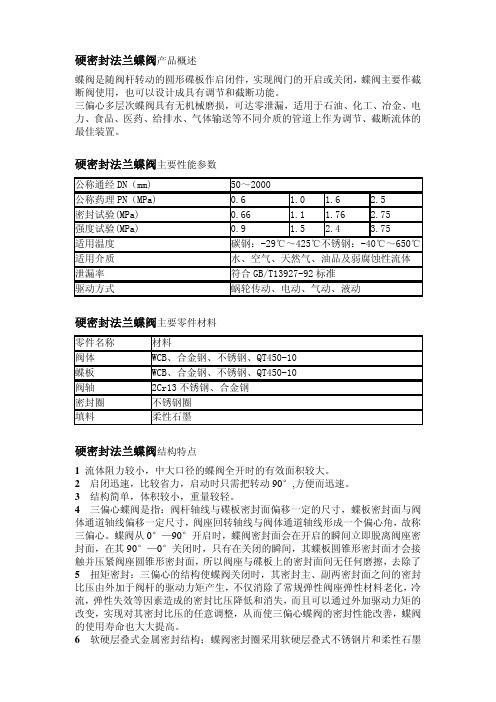
硬密封法兰蝶阀产品概述蝶阀是随阀杆转动的圆形碟板作启闭件,实现阀门的开启或关闭,蝶阀主要作截断阀使用,也可以设计成具有调节和截断功能。
三偏心多层次蝶阀具有无机械磨损,可达零泄漏,适用于石油、化工、冶金、电力、食品、医药、给排水、气体输送等不同介质的管道上作为调节、截断流体的最佳装置。
硬密封法兰蝶阀主要性能参数公称通经DN(mm) 50~2000公称药理PN(MPa) 0.6 1.0 1.6 2.5密封试验(MPa) 0.66 1.1 1.76 2.75强度试验(MPa) 0.9 1.5 2.4 3.75适用温度 碳钢:-29℃~425℃不锈钢:-40℃~650℃适用介质 水、空气、天然气、油品及弱腐蚀性流体 泄漏率 符合GB/T13927-92标准驱动方式 蜗轮传动、电动、气动、液动硬密封法兰蝶阀主要零件材料零件名称 材料阀体 WCB、合金钢、不锈钢、QT450-10蝶板 WCB、合金钢、不锈钢、QT450-10阀轴 2Cr13不锈钢、合金钢密封圈 不锈钢圈填料 柔性石墨硬密封法兰蝶阀结构特点1流体阻力较小,中大口径的蝶阀全开时的有效面积较大。
2 启闭迅速,比较省力,启动时只需把转动90°,方便而迅速。
3结构简单,体积较小,重量较轻。
4三偏心蝶阀是指:阀杆轴线与碟板密封面偏移一定的尺寸,蝶板密封面与阀体通道轴线偏移一定尺寸,阀座回转轴线与阀体通道轴线形成一个偏心角,故称三偏心。
蝶阀从0°—90°开启时,蝶阀密封面会在开启的瞬间立即脱离阀座密封面,在其90°—0°关闭时,只有在关闭的瞬间,其蝶板圆锥形密封面才会接触并压紧阀座圆锥形密封面,所以阀座与碟板上的密封面间无任何磨擦,去除了5 扭矩密封:三偏心的结构使蝶阀关闭时,其密封主、副两密封面之间的密封比压由外加于阀杆的驱动力矩产生,不仅消除了常规弹性阀座弹性材料老化,冷流,弹性失效等因素造成的密封比压降低和消失,而且可以通过外加驱动力矩的改变,实现对其密封比压的任意调整,从而使三偏心蝶阀的密封性能改善,蝶阀的使用寿命也大大提高。
阀门维修手册最终版-第二章
其次章阀门安装、运行管理及大修手册阀门的维护与管理包括提货搬运、库存保管和安装使用的全过程,它是阀门正常运转的一项重要的保证措施。
第一节阀门运输途中的维护阀门的手轮破损、阀杆弯曲、支架断裂、法兰密封面的磕碰损坏,特殊是灰铸铁阀门的损坏,相当一部分消灭在阀门运输过程中。
造成上述损坏的缘由,主要是运输人员对阀门的基本常识不甚了解和野蛮装卸作业造成的。
运输阀门之前,应当预备好绳索、起吊设备和运输工具等。
检查阀门包装,包装损坏的应当修订好,不能怕麻烦,不能存有侥幸心理;包装要符合标准要求,不允许任凭旋转已包装封存阀门的手轮;阀门应当处于全闭状态,对已误开启的阀门,应当将密封面擦洁净后再关闭紧,封闭进出口通道。
传动装置应当与阀门分别包装运输。
阀门装运起吊时,绳索应当系在法兰处或支架上,切忌系在手轮或阀杆上。
阀门吊装要轻起轻放,不要撞击他物,放置要平稳。
放置姿势应当直立或斜立,阀杆向上。
对放置不稳妥的阀门,应用绳索捆牢,或用垫块固定牢,以免在运输中相互碰撞。
手工装卸阀门时,不允许把阀门从车上往下扔,也不允许从地上向车上抛;搬运过程中应当有条不紊,顺次排列,严禁堆放。
阀门运输中,要疼惜油漆、铭牌和法兰密封面;不允许在地面上拖拉阀门,更不允许将阀门进出口密封面落地移动。
在施工现场暂担忧装的阀门,不要拆开包装,应当放置在平安的地方,并作好防雨、防尘工作。
其次节阀门保管中的维护阀门运输进入仓库后,保管员应当准时办理入库手续,这样有利于阀门的检查和保管。
保管员应当认真核对阀门的型号规格,检查阀门外观质量,并帮忙检验人员对阀门进行入库前的强度试验和密封性试验。
符合验收标准的阀门,可办理入库手续;对不合格的也应妥当保管,待有关部门处理。
对入库的阀门,要认真擦拭、清洗阀门在运输过程中的积水和灰尘脏物;对简洁生锈的加工面、阀杆、密封面应当涂上一层防锈剂或贴上一层防锈纸加以爱护;对阀门进出口通道要用塑料盖或蜡纸加以封闭,以免脏物进入。
蝶阀检修—完
#1机蝶阀检修技术措施
一、检修质量和标准:
1.阀门开关灵活,无内漏现象,密封结合面密封良好,无泄露现象。
2.更换的阀门安装位置正确,介质流向正确,焊接工艺符合要求,阀门开关灵活,无内漏现象,密封结合面密封良好,无泄露现象。
三、检修方案
3.1 蝶阀检修
解体
1.通知热控人员拆除电动头电源线。
2.拆除电动头与阀体连接螺栓,取下电动头并保存好。
3.松开盘根压盖螺栓退出盘根。
4.将盘根室内盘根掏出,测量盘根规格尺寸,并做好记录。
清理检查
1.清理盘根室内脏污,盘根室内干净无脏污。
2.检查阀杆弯曲度、椭圆度,应符合标准,必要时应进行更换。
3.检查阀体表面有无锈蚀、裂纹、麻坑等缺陷。
回装
1.将新盘根装入盘根室内,新盘根规格尺寸应与旧盘根一致。
2.盘根切口应为45°,每层切口相互错开90—120°,盘根与阀杆间隙应符合标准。
3. 更换新盘根后阀杆应转动灵活无卡涩。
4. 紧固盘根压盖,螺栓紧力均匀。
5.安装电动头,用螺栓将电动头与阀门进行连接,螺栓紧力均匀。
6.通知热控人员连接电动头电源线。
7.回装完成。
阀门维修手册最终版-第九章
第九章阀门的堵漏第一节堵漏的知识堵漏技术是一门新型的特殊的密封学,它处在发展中,方兴未艾。
它是设备、管道、阀门等密封体,在不停产、不停车、带压、带温的状态下,对其泄漏部位进行修复工作,以便恢复或重建受压体密封性能的一项专门技术。
一、泄漏的分类简单地说,不允许泄漏的部位产生了泄漏,或允许有一定泄漏量的部位实际泄漏量超过了规定值,这种现象称为泄漏。
我们平时所讲的“不泄漏”或“无泄漏”是指实际泄漏很微小而又感觉不出来。
因此,人们规定某一数量级的泄漏为零泄漏,又叫无泄漏。
根据不同角度,泄漏又可分为许多类。
1.按照泄漏量可以分为:液态介质可分为无泄漏、渗汗、滴漏、重漏、流淌五级;气态介质可分为无泄漏、渗漏、泄漏、重漏四级。
2.按照泄漏时间可以分为:可分为经常性泄漏、间歇性泄漏、突发性泄漏三种。
突发性泄漏最危险。
3.按照泄漏机理可以分为:可分为界面泄漏、渗透泄漏、破坏性泄漏三种。
破坏性泄漏危险性最大。
4.按照泄漏密封部位可以分为:可分为静密封泄漏、动密封泄漏、关启件泄漏、本体泄漏。
其中关启件泄漏最难治理,其次是动密封泄漏。
5.按照泄漏危害可以分为:可分为不允许泄漏、允许泄漏、允许微漏。
6.按照泄漏介质流向可以分为:可分为向外泄漏、向内泄漏、内部泄漏。
内部泄漏最难治理。
7.按照泄漏介质分:可分为漏气、漏汽、漏水、漏油等。
泄漏产生原因可分为纵向和横向两大类。
如设计不良、制造不精、安装不正、操作不当、维修不周,可谓纵向原因。
如受压系统内外压差、结合面间隙大小、密封结构形式、密封材料性能不同、介质性能(粘度、腐蚀性、浸润性、辐射性、导热性及介质分子大小等)优劣、内外温度高低及变化、轴与孔偏心距、旋转的线速度、往复次数,润滑状态好坏、振动和冲击的大小等因素的影响可谓横向原因了。
二、堵漏的安全技术堵漏的本身是带压、带温操作的,具有一定难度和危险性,只要操作人员掌握了堵漏的安全技术,严格遵守堵漏的操作规程,堵漏中的事故是可以避免的。
阀门维修手册最终版-第七章
第七章阀件的修理组成阀门的零件称为阀件。
主要阀件有阀体、阀盖、阀杆、阀杆螺母、启闭件(阀瓣、闸、蝶板、球体、旋塞锥等)、支架、自动元件(弹簧、膜片等)、手轮(驱动装置)等。
阀件在压力、温度、腐蚀等多种因素交替作用下,都会不同程度地被损坏。
本章将介绍阀件材料、使用条件及各种修理方法。
由于阀件采用的标准不同,其尺寸也不同,因此,在阀件修理或重新制作时,应该反复核查原阀件的几何尺寸和采用的标准。
本章中所列出的有关阀件制作尺寸仅供参考。
一、非金属阀门在低压低温阀门中,非金属材料的应用已经越来越多。
非金属材料耐腐蚀性能强,成型方便,加工性能好,轻便价廉。
目前,用于阀门的非金属材料有:聚四氟乙烯、硬聚氯乙烯、酚醛塑料、聚酰胺、聚甲醛、聚苯醚、丁腈橡胶、搪瓷、玻璃钢、陶瓷等。
例如在医疗器械上应用的玻璃阀,它的特点是光洁、耐磨、透明。
陶瓷水封阀已用于石油、化工、造纸等部门。
但是,非金属材料由于耐温性差,强度较低,容易老化和具有一定的脆性等缺点,使它的应用受到一定的限制。
目前一般仅在公称压力≤1.0MPa,温度不超过200℃的条件下使用。
通常在工作温度≤60℃范围内使用。
常用的非金属材料有:聚四氟乙烯(F-4)、聚三氟乙烯(F-3)、酚醛塑料、聚酰胺、MC尼龙、聚全氟乙丙烯、聚苯醚、聚砜塑料、聚甲醛等。
下面我们将详细介绍这几种主要非金属材料的性能。
聚四氟乙烯(F-4)的主要性能:具有优良的耐高、低温性(-200℃~250℃),优异的耐化学腐蚀性(在王水、强碱、强腐蚀剂下都不会腐蚀),优异的介电性能和低的摩擦系数。
其缺点是刚性差、强度低、加工困难。
聚三氟乙烯(F-3) 的主要性能:能耐各种强酸、强碱和强氧化剂。
可用于制作在腐蚀性介质工作下的阀门零件。
酚醛塑料的主要性能:具有耐热、耐磨、耐化学腐蚀以及优良的电绝缘性能。
成品的稳定性好、价廉。
但不耐碱,着色性差。
聚酰胺的主要性能:具有高强度、良好的冲击性能,耐磨、耐疲劳、耐油,但吸水性很大,影响尺寸稳定,并使一些机械性能下降。
- 1、下载文档前请自行甄别文档内容的完整性,平台不提供额外的编辑、内容补充、找答案等附加服务。
- 2、"仅部分预览"的文档,不可在线预览部分如存在完整性等问题,可反馈申请退款(可完整预览的文档不适用该条件!)。
- 3、如文档侵犯您的权益,请联系客服反馈,我们会尽快为您处理(人工客服工作时间:9:00-18:30)。
目录一、产品特点和用途……………………………………………………二、工作原理和结构简述………………………………………………三、阀门标准和性能试验规范…………………………………………四、主要零件材料和结构简图……………………………………………五、主要外形尺寸(简图)………………………………………………六、装运和储存………………………………………………………七、安装……………………………………………………………八、试验和调整………………………………………………………九、操作和维护………………………………………………………十、可能发生的故障、原因及维修方法……………………………………一、产品特点和用途:本阀采用三偏心多层次密封结构,吸收国外同类产品结构和特点,克服了原有产品在使用中存在的缺陷,使其寿命更耐久,密封更可靠。
本阀门适用于各种管道上,特别是安装在循环水泵出口,作截止或调节介质流量之用,并可抑制泵启停时产生的冲击作用,不受介质流向的影响。
其结构特点有:阀门体积小、重量轻、结构紧凑、开启迅速、密封性能可靠、轻便省力、寿命长和维修方便。
在开启和关闭过程中,密封面间无摩擦。
密封圈采用复合材料压制而成,其厚度易于调整,实现阀门的可靠密封。
二、工作原理和结构简述:工作原理本蝶阀为三偏心多层次密封结构,即蝶板回转中心到阀体密封截面的偏心距a,蝶板回转中心到阀体中心线的距离b,以及阀体的斜锥密封面中心与阀体中心线的夹角β(见下图)。
本阀通过蜗轮蜗杆传动减速(电动阀门通过电动机经过蜗轮蜗杆传动减速),通过阀轴3带动蝶板2在90℃范围内旋转,使蝶板处于开启或关闭状态,达到连通或截断介质的目的。
由图知,阀门全开时,蝶板密封圈处于松驰状态,形状为椭圆形。
阀门关闭时,密封圈4受阀体密封面1和蝶板2的挤压,产生了两个方向上的弹性变形。
密封面在长轴方向上受到了向外的张力,在短轴方向上受到向内的压应力,长短轴产生不同方向的弹性变形。
从而使阀门密封面间的密封力逐渐达到最大值。
其特点有:l 固定住的叠层密封圈不发生弯曲和移动,在高密封载荷下,没有磨损;l 叠层密封圈与阀体精密配合,有效避开介质冲刷,提高使用寿命和密封效果;l 体积小、重量轻、启闭迅速;l 采用先进的三偏心金属复合锥斜切结构,可达到泄漏量为零。
l 更换阀体材质,采用不同密封圈复合夹层,可适用不同介质;l 精密锥楔设计,确保均匀的密封接触。
结构特点阀体密封圈采用浮动结构,蝶板密封圈材料为柔性石墨夹不锈钢,密封圈具有良好的抗撕裂、抗磨损,最低使用寿命10年。
蝶板工作时,一侧为工作压力,另一侧为无压时不泄漏,泄露量为零,且双向承压,循环水进口蝶阀的主要承压方向为顺水流方向,循环水出口蝶阀的主要承压方向为逆水流方向。
阀门开关限位装置可靠,无过开、过关现象,开度指示与蝶板实际位置一致。
阀体、蝶板、阀杆具有足够的强度和刚度,蝶板密封圈安装后能在阀体内部调整和更换。
电动装置有过力矩装置、计数器的行程控制机构、就地位置指示和远方接点,有2对常开及2对常闭接点;有全开全关触点,能满足就地及远方控制的要求。
电动装置可接受三相四线制380/220VAC。
电动装置能承受2倍的所需力矩而不产生永久变形和破坏;手、电动切换方式为电动优先的自动操作方式。
三、阀门标准和性能试验规范四、主要零件材料和结构简图结构简图五、主要外形尺寸(简图)六、装运和储存1、运输前的准备阀门端部通道和阀杆外露表面是关键的部位,应采取下列措施:(a)阀门内部应清除滞留水垢,保持阀门内腔清洁、干燥。
(b)阀门外露机加工面应涂防锈油。
(c)阀门端部应有防止法兰面等机械损伤的措施。
(d)阀门启闭件应处于关闭状态。
2、搬运搬运阀门时应适当加以注意,阀门决不能抛扔或跌落,特别是手轮和阀杆不应作大型阀门的起吊或悬挂点。
3、储存储运应注意的问题通常与运输准备工作相同。
但时间因素是很重要的,一般蝶阀的存放期根据密封圈材料的保质期确定,如果要延长存放阀门几个星期或数月,就需要耗资改善原存放条件。
阀门一般存放在室内,使阀门的实际温度始终高于露点温度。
如果阀门必须存放在室外,则应将其支撑起来而不要与地面接触并要用防水罩加以保护。
七、安装1、阀门的安装是决定阀门使用寿命的关键。
安装不当使阀门性能下降的可能性很大,因此,在安装阀门之前应确认以下几点:(a)仔细拆装阀门的包装物,对照材料、规范和明细表等清单,检查标签或标牌,以确保其符合订单要求;(b)必须注意附在阀门上或随同阀门一起的专用警告标签或标牌,并采取适当的措施;(c)检查阀门表示流向的标志,如标出了流动方向,则应按照规定的流向安装阀门;(d)通过阀门两端通道检查阀门内部是否清洁、有无异物和危害性的腐蚀。
去除专用的包装材料,如运输和搬运中用于防止阀瓣移动阻碍物;(e)在即将安装阀门前,检查与阀门相连接的管道是否清洁,是否有异物。
2、法兰连接阀门与管道的安装管法兰连接的密封性能取决于配对法兰面之间垫片材料的压缩变形。
螺栓连接所产生的机械作用力不但要抵抗会使接头松动的正常压力,而且还必须在垫片上保持必要的压缩应力。
应认识到“强力”使不对中的法兰达到足够的栓接力可能不适于保持垫片载荷和压力载荷,其结果会使连接部分产生泄漏。
为了保证法兰连接良好,应注意以下几点:(a)检查法兰配合面,如果发现有可能引起泄漏的缺陷(如果退刀时划出的较深的沟槽或误操作产生的表面压痕),应修整后方可安装;(b)铸铁法兰的安装比球墨铸铁法兰的安装要求高。
建议采用低强度钢的栓接,以减小由于法兰螺栓预紧力过大而使法兰应力超过规定的可能性。
在平面法兰上装平垫片能防止由于法兰螺栓力矩过大而使法兰破坏。
平面法兰不应与凸面法兰对装。
在铸铁法兰连接中尤其重要的是顶安装对中要好,以保证在没有过大栓接载荷的情况下能使垫片具有适当的压紧力;(c)检查垫片的材料。
对于使用低强度栓接的法兰连接铁制法兰,不应使用金属垫片(平垫片、沟槽式垫片、包覆垫片、波形垫片或缠绕垫片);(d)检查垫片抗有害缺陷或损伤的能力;(e)仔细操作以提供配对法兰良好的对中性。
在螺栓螺纹上涂适当的润滑剂。
装配时螺栓要按次序拧紧,使法兰和垫片的初始接触尽可能平整和平行。
螺栓要逐渐均匀拧紧,避免两个法兰相互扭曲。
使用力矩扳手有助于确保法兰螺栓连接的正确性及最后的均匀拧紧。
把阀门安装到原有的管道上,则法兰的平行对中尤其重要。
应认识到,如果法兰不平行,要使法兰连接密封,就必须使某些部位弯曲。
仅施加到法兰及螺栓上的力就可能使管子弯曲,或者使阀门弯曲。
特别是在大直径的管道上,这种情况经常引起估计弯曲强度条件的人员的注意,如果需要则应采取补救措施。
注意:正如前面所述,法兰栓接应用力矩扳手拧紧。
如果某一螺栓在拧紧过程中的转矩时而逐步增大、时而保持不变或稍有增大,则该螺栓已弯曲,应更换和报废。
八、试验和调整当阀门经严格检查和安装后,应处于良好的工作状态,并随时可以操作。
然而,阀门这时处于危险状态的最后时刻。
只有通过试验才能验证其操作性能。
这时,应检查阀杆密封,确定填料是否安装适当,填料压盖螺栓是否处于初期位置。
在检查阀门的操作性能并引入系统的介质压力时,应根据需要确定附加的调整量。
通过开-关或关-开循环操作进行观察。
如果没发现明显的问题,则在检查密封性能和操作性能的同时就可带压进行实际试验。
九、操作和维护阀门是一种既有运动件又有磨损件的特殊产品。
为了使阀门获得满意的使用性能,就要长期保护好某些部件的精加工表面。
在正常运行状态和符合压力、介质、温度的情况下,阀门连续的使用寿命不小于三年。
1、手动阀门的操作大多数阀门是通过某些线性运动或手轮、扳手和手柄等旋转运动进行手动操作,要小心仔细,不要太快或太慢,并在适当的距离处施力。
末端的位置对使用性能具有重要的作用。
在关闭位置,内部关闭件(蝶板)必须与阀座正确定位。
(a)关闭件在阀门中做靠近阀座和离开阀座运动的阀门,阀门的密封性能在某种程度上取决于阀杆驱动关闭件相对阀座使之保持密封而产生的机械作用力。
如果作用在关闭件某一个方向上的关闭压力把关闭件推离阀座,那么这个力是至关重要的。
多数内部关闭件在阀座上滑动的阀门不靠阀杆作用力密封,但这类阀门关闭件的位置正确与否是很重要的。
在某些情况下,当关闭件接近最终关闭位置时,驱动关闭件所需的作用力可能大大增加,给已达到规定位置的关闭件一个辅助压缩。
关闭件不能到达或没有停止在全关位置会产生泄漏和损伤密封件。
蝶阀要求关闭件正确定位,以保证密封。
在到达确定的停止位置或位置指示器到达“关闭”位置指示时,方可停止关闭运动。
(b)使用易燃介质的软质阀座和密封圈的碟阀必须提供在软质密封毁坏时能立即工作的密封。
由于阀杆的转动为1/4周,流体压力在关闭件上的分布可产生很大的开启或关闭力矩。
如果不加以有力的限制,阀门就会突然开启或关闭,并有可能引起“水锤”,破坏阀门的结构。
另外要考虑可能会击伤操作者。
2、动力驱动阀门的操作从功能上讲,关闭件的性能和上密封的设置主要与阀门类型本身有关,而与操作方式无关,动力操作阀门要得到满意的效果需将各种合理的程序存放到驱动装置控制器内。
这样,驱动装置应调整到能够传递适当的开启、转动和关闭力,以适应预定的使用工况和阀门的类型。
关闭件位置要求比较严格的阀门,应当用位置控制关闭,例如采用外部限位开关。
3、维护阀门是压力容器和操作机械的混合结构,对它的维护要求既要考虑阀门的偶然开启与关闭,又要考虑到阀门大部分时间是处于承压不动状态。
长期保持在某个位置不动的阀门,可操作性在某种程度上可能会下降,这是由于填料老化、运动部件表面腐蚀或有害的堆积而造成的。
在有些使用场合,最后要制定这类阀门周期性的部分或全部循环计划。
承压边界的完整性主要是要求承压部件完好无损,固定装配连接处的承压密封,以及在大多数情况下保证运动的阀杆和阀盖之间有效的工作密封。
承压边界和固定装配连接处要经常检查并确认是好的。
阀杆密封的泄漏通常是由于填料磨损引起的,一般可通过拧紧填料压盖加以弥补。
过大的压紧力可能会使阀杆的摩擦力升高,使阀杆难以操作并加速填料的磨损。
内密封较好的阀门由于损伤或正常磨损而影响其密封性能。
由于使用工况的恶劣,密封有效性的估算和修复超出了本手册的规定范围,因为各种结构形式差异很大,如果需要预先知道应与制造厂合作以寻得合适的方法。
阀门的外部结构一般很容易检查和维护。
应采取合理的方法防止阀门的机械损伤,防止大气中的沉淀物、化学物质或潮湿气体对阀门的侵蚀而使其品质恶化。
螺纹、轴承或齿轮之类的工作交界面应定期润滑。