用verilog编写的反Z变换程序
Verilog中的一些语法和技巧

Verilog中的⼀些语法和技巧1、.2、.3、Reg型的数据类型默认初始值为X。
reg型数据可以赋正值也可以赋负值,但是当⼀个reg型数据是⼀个表达式的操作数的时候,他的值被当做⽆符号数及正值。
4、在数据类型中?和Z均表⽰⾼阻态。
5、Reg型只表⽰被定义的信号将⽤在“always”模块内,并不是说reg型⼀定是寄存器或触发器的输出。
虽然reg型信号常常是寄存器或触发器的输出但是并不⼀定总是这样。
6、Verilog语⾔中没有多维数组的存在。
Memory型数据类型是通过扩展reg型数据的弟⼦和范围来⽣成的。
其格式如下reg[n-1:0]存储器名[m-1:0];7、在除法和取余的运算中结果的符号和第⼀个操作数的符号位是相同的。
8、不同长度的数据进⾏运算:两个长度不同的数据进⾏位运算时,系统会⾃动地将两者按有端对齐,位数少的操作数会在相应的⾼位⽤0填满以便连个操作数安慰进⾏操作。
9、= = =与!= = =和= =与!= =的区别:后者称为逻辑等是运算符,其结果是2个操作数的值决定的。
由于操作书中某些位可能不定值x和⾼阻态z结果可能是不定值x。
⽽ = = =和!= = =运算符对操作数的⽐较时对某些位的⾼阻态z和不定值x也进⾏⽐较,两个操作数必须完全⼀致,其结果才是1,否则是0.10、⾮阻塞和阻塞赋值⽅式:⾮阻塞赋值⽅式(如a<=b)上⾯语句所赋得变量值不能⽴即被下⾯语句所⽤,(2)快结束后才能完成这次赋值操作 3在编写克综合的时序逻辑模块时这是最常⽤的赋值⽅法。
阻塞赋值(如a=b)赋值语句执⾏完后,块才结束 2 b的值在赋值语句完成后⽴即执⾏ 3在时序逻辑使⽤中,可能产⽣意想不到的结果。
11、模块的描述⽅式:(RTL为寄存器传输级描述)“(1)数据流描述⽅式:数据流⾏描述主要⽤来描述组合功能,具体⽤“assign”连续赋值语句来实现。
分为两种a、显式连续赋值语句;连线型变量类型[连线型变量为快]连线型变量名Assign #(延时量)连线型变量名=赋值表达式;显式连续赋值语句包含了两条语句;第⼀条是对连线型变量的进⾏类型说明的说明语句;第⼆句是对这个已得到声明的连线型变量进⾏连续赋值语句。
systemverilog 逆序

systemverilog 逆序摘要:1.SystemVerilog 简介2.逆序的概念3.SystemVerilog 中的逆序操作4.逆序操作的实例5.总结正文:一、SystemVerilog 简介SystemVerilog 是一种硬件描述语言,主要用于设计和验证数字电路和模拟混合信号电路。
它是Verilog 的扩展,添加了许多新的功能和结构,以支持更复杂的设计和验证需求。
SystemVerilog 在电子设计自动化(EDA)领域广泛应用,为设计师提供了强大的工具和语言来描述和验证他们的设计。
二、逆序的概念逆序是一种逻辑运算,它的主要功能是将一个信号的顺序颠倒。
逆序在数字电路设计中具有重要作用,可以用于实现复杂的逻辑功能和数据路径。
逆序操作在SystemVerilog 中是一种基本的操作,可以方便地实现这一功能。
三、SystemVerilog 中的逆序操作在SystemVerilog 中,逆序操作可以通过关键字`reverse`实现。
`reverse`关键字可以用于信号、寄存器和数组等数据类型。
逆序操作的结果是将原始信号的顺序颠倒,从而实现逆序传输。
四、逆序操作的实例以下是一个简单的SystemVerilog 代码示例,演示了如何使用逆序操作:```verilogmodule tb_reverse(input wire clk,input wire reset,input wire signal_in,output wire signal_out);reg signal_in_reverse;always @(posedge clk or posedge reset) beginif (reset) beginsignal_in_reverse <= 1"b0;end else beginsignal_in_reverse <= signal_in;endendassign signal_out = signal_in_reverse;endmodule```在这个例子中,我们定义了一个名为`tb_reverse`的模块,它有一个输入信号`signal_in`,一个输出信号`signal_out`。
verilog串并转换并串转换
wire [7:0] b;
initial begin
a = 3'b000;
ena = 1'b0;
#50;
ena = 1'b1;
#50;
a=3'b001;
#50;
a=3'b010;
#50;
a=3'b011;
#50;
a=3'b100;
#50;
a=3'b101;
#50;
a=3'b110;
#50;
_______________________________________________________________________________
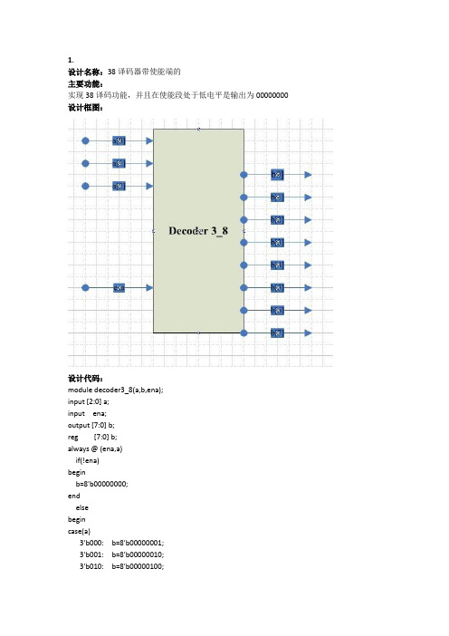
3.
设计名称:设计一个1:1的3分频器
主要功能:
实现3分频,同时高低电平比为1:1
设计框图:
设计代码:
这个设计可以利用模三计数器分别在时钟的上升和下降沿设计一个高低电平为1:2的3分频,然后将两个波形相或即能得到结果。
3'b101: b=8'b00100000;
3'b110: b=8'b01000000;
3'b111: b=8'b10000000;
default: b=8'b00000000;
endcase
end
endmodule
仿真代码:
`timescale 1ns/1ns
module tb;
reg [2:0] a;
`timescale 1ns/1ns
module q;
reg rst;
reg [6:0]vote;
wire Q;
verilog实现串并并串转换的代码和仿真结果
begin
r <= 4'h0;//如果复位信号rst_n为低电平输出0000
end
else if(load)//如果load信号为高电平,可以输入信号
begin
r <= pi;//把输入值r数组
end
else//如果load为低电平则完成输出功能
begin
r <= {r, 1'bx};//移位寄存器的实现,如果r输出到so,则给r已经输//出了的位置为x
if(r[3]||~r[3])//判断r寄存器是否已经全部清空为x
begin
so = r[3];
if(r[2]||~r[2])//在r2没有输出之前biaozhi为0
biaozhi=1'b0;
else//当r3刚刚跳变的瞬间,biaozhi变为1
biaozhi=1'b1;
end
else
begin
so=1'bx;//没有信号输入时so置为不定态
load <= 1'b1;
pi <= 4'b1100;
#20;
load <= 1'b0;
pi <= 4'hxxxx;
#90
load<=1'b1;
pi<=4'hxxxx;
reg [3:0] pi;
wire [3:0] po;
wire so;
reg flag;
//reg biaozhi;
initial begin
flag=1'b1;
#400;
flag=1'b0;
verilog中把小写字母替换成大写字母的函数
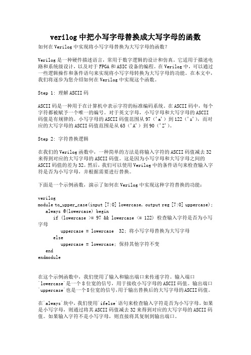
verilog中把小写字母替换成大写字母的函数如何在Verilog中实现将小写字母替换为大写字母的函数?Verilog是一种硬件描述语言,常用于数字逻辑的设计和仿真。
它适用于描述电路和系统级设计,以及对于FPGA和ASIC设备的编程。
在Verilog中,可以通过一些逻辑操作和条件语句来实现将小写字母转换为大写字母的功能。
在本文中,我们将逐步为您介绍如何在Verilog中实现这个函数。
Step 1: 理解ASCII码ASCII码是一种用于在计算机中表示字符的标准编码系统。
在ASCII码中,每个字符都被赋予一个唯一的编号。
对于英文字母,小写字母和大写字母的ASCII码值是有规律的。
小写字母的ASCII码值范围从97('a')到122('z'),而对应的大写字母的ASCII码值范围是从65('A')到90('Z')。
Step 2: 字符替换逻辑在我们的Verilog函数中,一种简单的方法是将输入字符的ASCII码值减去32来得到对应的大写字母的ASCII码值。
这是因为小写字母和大写字母之间的ASCII码值的差为32。
然后,我们可以使用Verilog中的条件语句来检查输入字符是否为小写字母,并根据需要进行替换。
下面是一个示例函数,演示了如何在Verilog中实现这种字符替换的功能:verilogmodule to_upper_case(input [7:0] lowercase, output reg [7:0] uppercase); always @(lowercase) beginif (lowercase >= 97 && lowercase <= 122) 检查输入字符是否为小写字母uppercase = lowercase 32; 将小写字母替换为大写字母elseuppercase = lowercase; 保持其他字符不变endendmodule在这个示例函数中,我们使用了输入和输出端口来传递字符。
verilog 获取稀疏矩阵求逆算法

verilog 获取稀疏矩阵求逆算法
摘要:
1.引言
2.稀疏矩阵与逆矩阵
3.逆矩阵求解方法
4.基于Verilog 的求逆算法实现
5.总结
正文:
1.引言
矩阵求逆是线性代数中的一个重要概念,逆矩阵可以用于矩阵的行列式计算、线性方程组求解等。
对于稀疏矩阵,由于其特殊的结构,求逆算法相对于稠密矩阵更为高效。
本文将介绍一种基于Verilog 的稀疏矩阵求逆算法。
2.稀疏矩阵与逆矩阵
稀疏矩阵是一种特殊的矩阵,其非零元素占据较小的篇幅。
由于稀疏矩阵的特殊性,可以采用压缩存储的方式进行存储,从而节省空间。
逆矩阵是矩阵的一种逆运算,求逆矩阵的过程就是寻找一个矩阵,使得该矩阵与原矩阵的乘积等于单位矩阵。
3.逆矩阵求解方法
对于稀疏矩阵的求逆,常用的方法有高斯消元法、LU 分解法等。
这些方法都可以通过迭代的方式求解逆矩阵。
其中,LU 分解法由于具有较好的数值稳定性,在实际应用中更为广泛。
4.基于Verilog 的求逆算法实现
本文将以LU 分解法为例,介绍如何基于Verilog 实现稀疏矩阵求逆算法。
首先,需要对稀疏矩阵进行LU 分解,将矩阵分解为下三角矩阵与上三角矩阵的乘积。
然后,利用高斯消元法求解逆矩阵。
最后,将求得的逆矩阵进行存储。
5.总结
本文介绍了基于Verilog 的稀疏矩阵求逆算法,通过LU 分解法与高斯消元法实现。
该方法可以有效地应用于硬件实现中,对于稀疏矩阵的求解具有较高的效率。
NRZ(不归零码)转换位Manchester码的verilog实现
NRZ(不归零码)转换位Manchester码的verilog实现码字转换器能够将数据流变换成⼀种已编码的格式,使接受机能够恢复数据。
接下来介绍四种常⽤的串⾏编码⽅法。
如果⾮归零码(NRZ)格式的数据流中,没有1或0的长序列,那么采⽤锁相环电路PLL就可以从该线数据中恢复出时钟(即将其⾃⾝与数据时钟同步);如果⾮归零反转码(NRZI)或者归零码(RZ)格式的数据流中不存在0的长序列,时钟就可以从数据流中恢复出来。
由于曼彻斯特(Manchester)码从数据中恢复时钟时与数据⽆关,因⽽很有吸引⼒,不过它需要更⼤的带宽。
⾸先给出Mealy型状态机表⽰的转换器代码及其测试代码/*Mealy型状态机输出不仅与当前状态有关,还与输⼊有关*/module NRZ_to_Manchester_Mealy(output reg B_out,input B_in, clk, reset_b);parameter S_0=2'd0,S_1=2'd1,S_2=2'd2,dont_care_state=2'bx,dont_care_out=1'bx;reg[1:0] state, next_state;always@(posedge clk or negedge reset_b)if(!reset_b)state<=S_0;elsestate<=next_state;always @(state, B_in)begin//这⾥的敏感列表最好不要包含B_in,否则会有⽆效输出//Mealy型状态机输出虽然与输⼊有关,但不⼀定因输⼊⽽变化,只会//因输⼊有不同的变化B_out=0;case(state)S_0:if(B_in)beginB_out=1;next_state=S_1;endelsenext_state=S_2;S_1:next_state=S_0;S_2:beginnext_state=S_0;B_out=1;enddefault:beginnext_state=dont_care_state;B_out=dont_care_out;endendcaseendendmodule测试代码:module NRZ_to_Manchester_Mealy_tb;reg clk, reset_b;reg B_in;wire B_out;reg count;initial beginclk=0;reset_b=1;B_in=0;count=0;#20 reset_b=0;#10 reset_b=1;#10000 $finish;endinitial begin$dumpfile("dump.lxt");$dumpvars(0,NRZ_to_Manchester_Mealy_tb);endinitialforever #10 clk=!clk;always @(posedge clk)count=count+1;always @(negedge clk)if(count)B_in={$random}%2;NRZ_to_Manchester_Mealy uut(.B_out(B_out),.B_in(B_in),.clk(clk),.reset_b(reset_b));endmodule对于Moore型状态机所表⽰的转换器,输出只与状态有关,⽽与输⼊⽆关。
systemverilog 逆序
systemverilog 逆序摘要:1.什么是SystemVerilog2.SystemVerilog逆序的基本概念3.SystemVerilog逆序的语法和规则4.SystemVerilog逆序的例子和应用5.SystemVerilog逆序的重要性与实际应用场景正文:SystemVerilog是一种硬件描述语言,广泛应用于集成电路(IC)设计、验证和仿真。
作为一种高级硬件描述语言,SystemVerilog提供了许多强大的特性,以满足复杂数字电路设计的需要。
在这篇文章中,我们将详细介绍SystemVerilog逆序的基本概念、语法和规则,并通过实例演示其在实际应用中的重要性。
1.什么是SystemVerilogSystemVerilog是一种基于Verilog的硬件描述语言,它是在1995年由Cadence Design Systems公司推出的。
SystemVerilog在Verilog的基础上增加了许多新的特性,例如结构描述、数据类型、操作符、函数和任务等。
这些特性使SystemVerilog比Verilog更加灵活和强大,能够更好地描述和验证复杂的数字电路。
2.SystemVerilog逆序的基本概念逆序(Reverse Polish Notation,RPN)是一种计算表达式的数学表示方法,与传统的波兰表示法(Polish Notation,PN)相比,RPN更加高效。
在SystemVerilog中,逆序是一种用于描述和计算表达式的高级语法,可以显著提高代码的可读性和可维护性。
3.SystemVerilog逆序的语法和规则在SystemVerilog中,逆序表达式通常由操作数、运算符和括号组成。
操作数可以是变量、常数或表达式,运算符包括加法(+)、减法(-)、乘法(*)和除法(/)等。
逆序表达式的基本规则如下:- 先计算括号内的表达式- 计算乘法和除法- 计算加法和减法4.SystemVerilog逆序的例子和应用下面是一个使用SystemVerilog逆序的简单例子:```integer a, b, c;a = 5;b = 3;c = a * b + a / b; // 逆序表达式```在这个例子中,我们定义了两个整数变量a和b,然后计算a与b的乘积加上a除以b的结果,存储在变量c中。
verilog自动手动换挡频率计
直接上源码,不解释,自己建工程运行即可看到功能!module control(cp1024hz,started,reset,k1,k2,k3,k4,k5,k6,zero1,zero2,zero3,zero4,zero5,zero6,time_out,mode,flag_pressed,sound_en,latch_en);//yesdinput cp1024hz,started,reset;input k1,k2,k3,k4,k5,k6;//抢答的6个按键,由cp1024hz扫描是否有按键input zero1,zero2,zero3,zero4,zero5,zero6;//6个用?的分数是否为0,并将分数为0的淘汰input time_out;//倒计时已完output flag_pressed,sound_en,latch_en,mode;//是否已按键;声音控制;模式控制;输出模式regflag_pressed,sound_en,latch_en;reg[3:0] mode;always @(posedge cp1024hz)beginif(!started)//当started=0时,对系统进行初始化,同时将mode置0;beginmode<=0;flag_pressed<=1; //利用设置这个将k1~k6屏蔽sound_en<=0;latch_en<=0;endelsebeginif(reset) //started=1已开始,reset=1新一轮抢答beginflag_pressed<=0;sound_en<=0;latch_en<=0;mode<=7; //mode置为抢答模式endelsebeginif(time_out)beginsound_en<=1;//时间完了之后,响声提示endbeginif(!flag_pressed&& k1 && !zero1)//当started=1时,按下key1 beginflag_pressed<=1;sound_en<=1;latch_en<=1; //按键之后,产生相应电平mode<=1;endelse if(started && !flag_pressed&& k2 && !zero2)beginflag_pressed<=1;sound_en<=1;latch_en<=1; //按键之后,产生相应电平mode<=2;endelse if(!flag_pressed&& k3 && !zero3)beginflag_pressed<=1;sound_en<=1;latch_en<=1; //按键之后,产生相应电平mode<=3;endelse if(!flag_pressed&& k4 && !zero4)beginflag_pressed<=1;sound_en<=1;latch_en<=1; //按键之后,产生相应电平mode<=4;endelse if(!flag_pressed&& k5 && !zero5)beginflag_pressed<=1;sound_en<=1;latch_en<=1; //按键之后,产生相应电平mode<=5;endelse if(!flag_pressed&& k6 && !zero6)beginflag_pressed<=1;sound_en<=1;latch_en<=1; //按键之后,产生相应电平mode<=6;endendendendendmodulemoduledisplay(cp1024hz,mode,setted_score,score1,score2,score3,score4,score5,score6,time_countdow n,disp);//yesdinput cp1024hz;input[3:0] mode,time_countdown;//从time_count引出input[7:0] setted_score,score1,score2,score3,score4,score5,score6;outputdisp;reg [3:0]mode_disp;reg[7:0] disp;always @(posedge cp1024hz)begincase(mode)4'b0000 :disp<=setted_score;4'b0001 :disp<=score1;4'b0010 :disp<=score2;4'b0011 :disp<=score3;4'b0100 :disp<=score4;4'b0101 :disp<=score5;4'b0110 :disp<=score6;4'b0111 :begindisp[3:0]<=time_countdown;disp[7:4]<=0;enddefault :disp<=setted_score;endcaseendendmodulemodulemode_latch_change(cp1024hz,started,flag_pressed,latch_clk,up_clk,down_clk,mode_in,mode_out);input cp1024hz,started,flag_pressed;//yesdinput latch_clk;//锁存mode的信号input up_clk,down_clk;//设置mode按键,上调和下调input[3:0]mode_in;//从control的mode输出引进outputmode_out;reg[3:0] mode_out;reg up_clk1,down_clk1,latch_clk1;always @(posedge cp1024hz)beginup_clk1<=up_clk;down_clk1<=down_clk;latch_clk1<=latch_clk;endwire up_clk2,down_clk2,latch_clk2;//对输入的信号的变化,便于cp1024hz的脉冲捕获assign up_clk2=up_clk1&(~up_clk);assign down_clk2=down_clk1&(~down_clk);assign latch_clk2=latch_clk1&(~latch_clk);always @(posedge cp1024hz)beginif(!started)//started=0,设置分数模式,mode_out=mode_in=0;beginmode_out<=0;endelse//正常工作beginif(!flag_pressed)//抢答模式beginmode_out<=mode_in;endelse if(latch_clk2)//锁存模式beginmode_out<=mode_in;endelse if(flag_pressed&& up_clk2)//查看各个分数,mode加计数beginif(mode_out>=6)beginmode_out<=0;endelsebeginmode_out<=mode_out+1;endendelse if(flag_pressed&& down_clk2)//查看各个分数,mode减计数beginif(mode_out<=0)beginmode_out<=6;endelsebeginmode_out<=mode_out-1;endendelsebegin// mode_out<=mode_in;endendendendmodulemodule restart(cp1024hz,start_clk,started);//started==0设置初始分数,started==1开始工作input cp1024hz,start_clk; //yesdoutput started;reg started;reg start_clk1;always @(posedge cp1024hz)beginstart_clk1<=start_clk;endwire start_clk2;assign start_clk2=start_clk1&(~start_clk);//变换start_clk信号,防止抖动以及便于cp1024hz扫描always @(posedge cp1024hz)//start正常工作抢答_clk翻转,started翻转,为0时设置分数,为1时beginif(start_clk2)beginstarted<=~started;endendendmodulemodule score_count(cp1024hz,started,reset,mode,time_out,right_key,wrong_key,setted_score,score1,score2,score3,score4,score5,score6,zero1,zero2,zero3,zero4,zero5,zero6);//yesdinput cp1024hz,started,reset;input time_out;//时间完了之后却没有是抢答input right_key,wrong_key;//每次抢答之后主持人用于判断抢答者回答是否正确,从而设置分数input[3:0] mode;//从control的mode输出引进input[7:0] setted_score;//mode=0时设置的厨师分数output score1,score2,score3,score4,score5,score6;//各玩家分数output zero1,zero2,zero3,zero4,zero5,zero6;//玩家分数是否为0reg zero1,zero2,zero3,zero4,zero5,zero6;reg [7:0]score1,score2,score3,score4,score5,score6;reg right1,wrong1;always @(posedge cp1024hz)beginright1<=right_key;wrong1<=wrong_key;endwire right2,wrong2;//将判断回答对错的信号变换,消除抖动以及便于扫描识别assign right2=right1&(~right_key);assign wrong2=wrong1&(~wrong_key);regtemp_flag;//用于消除多次判断回答对错,防止扣分错误always @(posedge cp1024hz)beginif(!started)//设置分数时,对各个玩家分数初始化beginscore1<=setted_score;score2<=setted_score;score3<=setted_score;score4<=setted_score;score5<=setted_score;score6<=setted_score;zero1<=0;zero2<=0;zero3<=0;zero4<=0;zero5<=0;zero6<=0;temp_flag<=0;endelse //started=1,正常工作模式beginif(reset) //reset之后初始化参数begintemp_flag<=0;endelse //进行回答判断beginif(!time_out&& !temp_flag&& wrong2)//回答错误,减1分begintemp_flag<=1;//标志位置1,防止再次按键case(mode)4'b0001 : //如果抢答为玩家1beginif(score1[3:0]==0 && score1[7:4]>=1)beginscore1[3:0]<=9;score1[7:4]<=score1[7:4]-1;endelse if(score1[3:0]==1 && score1[7:4]==0)beginscore1[7:0]<=0;zero1<=1;//玩家1的分数减少到0,淘汰endelsebeginif(score1[7:0]!=0)beginscore1[3:0]<=score1[3:0]-1;endendend4'b0010 : //如果抢答为玩家2beginif(score2[3:0]==0 && score2[7:4]>=1)beginscore2[3:0]<=9;score2[7:4]<=score2[7:4]-1;endelse if(score2[3:0]==1 && score2[7:4]==0)beginscore2[7:0]<=0;zero2<=1;endelsebeginif(score2[7:0]!=0)beginscore2[3:0]<=score2[3:0]-1;endendend4'b0011 : //如果抢答为玩家3beginif(score3[3:0]==0 && score3[7:4]>=1)beginscore3[3:0]<=9;score3[7:4]<=score3[7:4]-1;endelse if(score3[3:0]==1 && score3[7:4]==0)beginscore3[7:0]<=0;zero3<=1;endelsebeginif(score3[7:0]!=0)beginscore3[3:0]<=score3[3:0]-1;endendend4'b0100 : //如果抢答为玩家4beginif(score4[3:0]==0 && score4[7:4]>=1)beginscore4[3:0]<=9;score4[7:4]<=score4[7:4]-1;endelse if(score4[3:0]==1 && score4[7:4]==0)beginscore4[7:0]<=0;zero4<=1;endelsebeginif(score4[7:0]!=0)beginscore4[3:0]<=score4[3:0]-1;endendend4'b0101 : //如果抢答为玩家5beginif(score5[3:0]==0 && score5[7:4]>=1)beginscore5[3:0]<=9;score5[7:4]<=score5[7:4]-1;endelse if(score5[3:0]==1 && score5[7:4]==0)beginscore5[7:0]<=0;zero5<=1;endelsebeginif(score5[7:0]!=0)beginscore5[3:0]<=score5[3:0]-1;endendend4'b0110 : //如果抢答为玩家6beginif(score6[3:0]==0 && score6[7:4]>=1)beginscore6[3:0]<=9;score6[7:4]<=score6[7:4]-1;endelse if(score6[3:0]==1 && score6[7:4]==0)beginscore6[7:0]<=0;zero6<=1;endelsebeginif(score6[7:0]!=0)beginscore6[3:0]<=score6[3:0]-1;endendenddefault : ;endcaseendif(!time_out&& !temp_flag&& right2)//回答正确,相应加1分begintemp_flag<=1;case(mode)4'b0001 : //玩家1if(score1[3:0]==9)beginscore1[3:0]<=0;score1[7:4]<=score1[7:4]+1;endelsebeginscore1[3:0]<=score1[3:0]+1;end4'b0010 : //玩家2if(score2[3:0]==9)beginscore2[3:0]<=0;score2[7:4]<=score2[7:4]+1;endelsebeginscore2[3:0]<=score2[3:0]+1;end4'b0011 : //玩家3if(score3[3:0]==9)beginscore3[3:0]<=0;score3[7:4]<=score3[7:4]+1;endelsebeginscore3[3:0]<=score3[3:0]+1;end4'b0100 : //玩家4if(score4[3:0]==9)beginscore4[3:0]<=0;score4[7:4]<=score4[7:4]+1;endelsebeginscore4[3:0]<=score4[3:0]+1;end4'b0101 : //玩家5if(score5[3:0]==9)beginscore5[3:0]<=0;score5[7:4]<=score5[7:4]+1;endelsebeginscore5[3:0]<=score5[3:0]+1;end4'b0110 : //玩家6if(score6[3:0]==9)beginscore6[3:0]<=0;score6[7:4]<=score6[7:4]+1;endelsebeginscore6[3:0]<=score6[3:0]+1;enddefault : ;endcaseendendendendendmodulemodule set_score(cp1024hz,started,set_up,set_down,setted_score);//抢答前设置玩家分数yes input cp1024hz,started,set_up,set_down;outputsetted_score;reg [7:0]setted_score;regcp_up,cp_down;always @(posedge cp1024hz)begincp_up<=set_up;cp_down<=set_down;endwirecp_up_pos,cp_down_pos;assign cp_up_pos=cp_up&(~set_up);assign cp_down_pos=cp_down&(~set_down) ;//设置分数的cp,防止抖动always @(posedge cp1024hz) //设置初始分数beginif(!started) //当stared=0,设置模式,开始设置分数beginif(cp_up_pos&&(!cp_down_pos)) //加分设置beginif(setted_score[3:0]==9)beginsetted_score[3:0]<=0;if(setted_score[7:4]==9)beginsetted_score[7:4]<=0;endelsebeginsetted_score[7:4]<=setted_score[7:4]+1;endendelsebeginsetted_score[3:0]<=setted_score[3:0]+1;endendelse if((!cp_up_pos)&&cp_down_pos) //减分设置beginif(setted_score[3:0]==0)beginsetted_score[3:0]<=9;if(setted_score[7:4]==0)beginsetted_score[7:4]<=9;endelsebeginsetted_score[7:4]<=setted_score[7:4]-1;endendelsebeginsetted_score[3:0]<=setted_score[3:0]-1;endendendendendmodulemodule sound_alarm(reset,sound_en,cp1024hz,time_less_alarm,alarm);//yesd input reset,sound_en,cp1024hz;inputtime_less_alarm;output alarm;reg [9:0] temp_count;reg temp;always @(posedge cp1024hz)//(包括倒计时完,已抢答两种情况的声音提示)beginif(reset)//对中间变量进行初始化begintemp<=1;temp_count<=0;endif(sound_en==1)beginif(temp_count==1023)//sound_en==1时,响1s钟提示begintemp<=0;endelsebegintemp_count<=temp_count+1;endendendwirealarm_time;assignalarm_time=temp &sound_en;reg[9:0] temp1;regtime_left_alarm;always @(posedge cp1024hz)//时间到三秒时提示声0.5sbeginif(reset)//对中间变量进行初始化begintemp1<=1;time_left_alarm<=0;endelsebeginif(time_less_alarm==0)begintemp1<=0;time_left_alarm<=0;endelsebegin//时间少于3s时提示if(temp1<=512)begintemp1<=temp1+1;time_left_alarm<=1;endelsebegintime_left_alarm<=0;endendendendassign alarm=(time_left_alarm|alarm_time)&cp1024hz;endmodulemoduletime_count(cp1024hz,started,reset,flag_pressed,time_left,time_less_alarm,time_out);//yesd input cp1024hz,started,reset,flag_pressed;outputtime_left;output time_less_alarm;//倒计时到3s之后发出提醒信号output time_out;//倒计时完了之后发出信号reg [3:0] time_left;regtime_less_alarm;regtime_out;reg[9:0] temp_count;always @(posedge cp1024hz)beginif(!started)begintime_left<=0;endelsebeginif(reset)begintime_left<=9;time_less_alarm<=0;time_out<=0;temp_count<=0;endelsebeginif(time_left==3)//当倒计时剩3s时,发出警报begintime_less_alarm<=1;endif(time_left==0)//当倒计时完了了,发出信号begintime_out<=1;endif(flag_pressed)//已抢答,则终止倒计时,并置为初值begintime_left<=9;endelse//还未抢答,进行倒计时beginif(temp_count==1023)begintemp_count<=0;if(time_left>1)begintime_left<=time_left-1;if(time_left==4)begintime_less_alarm<=1;endendelsebegintime_out<=1;time_left<=0;endendelsebegintemp_count<=temp_count+1;endendendendendendmodule使用的连线组装的模块!如下图所示!。
Verilog语言编程规范
前言 (IV)1范围 (1)2术语 (1)3代码标准 (1)3.1命名规范 (1)3.1.1文件命名 (1)3.1.2HDL代码命名总则 (2)3.2注释 (4)3.2.1文件头 (4)3.2.2其它注释 (5)3.3编程风格 (7)3.3.1编写代码格式要整齐 (7)3.3.2使用二到四个空格符缩排 (7)3.3.3一行一条Verilog语句 (7)3.3.4一行一个端口声明 (7)3.3.5在定义端口时,按照端口类型或端口功能定义端口顺序。
(8)3.3.6保持端口顺序一致。
(8)3.3.7声明内部net (8)3.3.8在一个段内声明所有内部net (8)3.3.9每行长度不超过80字符....................... 错误!未定义书签。
3.3.10代码流中不同结构之间用一空行隔开 (8)3.4模块划分和重用 (10)3.4.1不能访问模块外部的net和variable (10)3.4.2不使用`include编译指令 (10)3.4.3建议模块的端口信号尽可能少。
(10)3.4.4时钟产生电路单独构成一个模块 (10)3.4.5划分时钟域 (10)3.4.6物理和逻辑边界的匹配 (10)3.4.7特定应用代码要单独划分出来 (10)3.4.8关键时序逻辑划分 (10)3.4.9数据流逻辑划分 (11)3.4.10异步逻辑划分 (11)3.4.11状态机划分 (11)3.4.12控制逻辑和存储器划分 (11)3.5逻辑设计经验 (11)3.5.1时钟域要尽可能少,所用时钟尽可能加全局BUFF (11)3.5.2异步接口信号同步化 (11)3.5.3避免寄存器的数据与时钟异步 (11)3.5.4使用无毛刺的门控时钟使能信号 (11)3.5.5直接作用信号无毛刺 (11)3.5.6初始化控制存储元件 (12)3.5.7使用同步设计 (12)3.5.8避免组合反馈环 (12)3.6常用编程技巧 (12)3.6.1条件表达式的值必须是一个单bit值 (12)3.6.2总线位顺序按高到低保持一致 (12)3.6.3不要给信号赋x值 (12)3.6.4寄存器变量只能在一个always语句中赋值 (12)3.6.5对常量使用参数而不使用文本宏 (12)3.6.6不能重复定义参数 (12)3.6.7不能重复定义文本宏 (12)3.6.8保持常量之间的联系 (12)3.6.9状态编码的参数使用 (13)3.6.10`define、`undef配合使用 (13)3.6.11用基地址+地址偏移量生成地址 (13)3.6.12使用文本宏表示寄存器字段位置和值 (13)3.6.13`ifdef的嵌套限制在三层以内 (13)3.6.14操作数的位宽必须匹配 (13)3.6.15模块调用时端口要显式引用 (14)3.6.16矢量端口和net/variable声明的位宽要匹配 (14)3.6.17避免inout类型的端口 (14)3.6.18在复杂的表达式中使用括号 (14)3.7常用综合标准 (14)3.7.1always 的敏感列表要完整 (14)3.7.2一个 always 的敏感列表中只能有一个时钟 (14)3.7.3只使用可综合的结构 (15)3.7.4组合逻辑的条件需完备 (15)3.7.5循环结构中禁用disable语句 (15)3.7.6避免无界循环 (15)3.7.7端口连接禁用表达式 (15)3.7.8禁用Verilog primitive (15)3.7.9边沿敏感结构中使用非阻塞赋值(<=) (15)3.7.10Latch使用非阻塞赋值 (15)3.7.11模块闲置的输入端不要悬空 (15)3.7.12连接模块闲置的输出端 (16)3.7.13函数中不要使用锁存器 (16)3.7.14禁用casex (16)3.7.15多周期路径的信号使用单周期使能信号 (16)3.7.16三态元件建模 (16)3.7.17避免顶层胶合逻辑 (16)3.7.18在case语句中使用default赋值语句 (16)3.7.19full_case综合命令的使用 (16)附录1 HDL编译器不支持的Verilog结构 (18)附录2 Verilog和VHDL关键词列表 (19)前言编写本标准的目的是为了统一部门内部FPGA\EPLD设计用verilog语言编程风格,提高Verilog设计源代码的可读性、可靠性和可重用性,减少维护成本,最终提高产品生产力;并且以此作为代码走查的标准。
- 1、下载文档前请自行甄别文档内容的完整性,平台不提供额外的编辑、内容补充、找答案等附加服务。
- 2、"仅部分预览"的文档,不可在线预览部分如存在完整性等问题,可反馈申请退款(可完整预览的文档不适用该条件!)。
- 3、如文档侵犯您的权益,请联系客服反馈,我们会尽快为您处理(人工客服工作时间:9:00-18:30)。
/************************************************************************ -----------------------------------------------------------------------**** zigzag.v************ Author: Latha Pillai** Senior Applications Engineer**** Video Applications** Advanced Products Group** Xilinx, Inc.**** Copyright (c) 2001 Xilinx, Inc.** All rights reserved**** Date: April. 10, 2002**** RESTRICTED RIGHTS LEGEND**** This software has not been published by the author, and** has been disclosed to others for the purpose of enhancing** and promoting design productivity in Xilinx products.**** Therefore use, duplication or disclosure, now and in the** future should give consideration to the productivity** enhancements afforded the user of this code by the author's** efforts. Thank you for using our products !**** Disclaimer: THESE DESIGNS ARE PROVIDED "AS IS" WITH NO WARRANTY** WHATSOEVER AND XILINX SPECIFICALLY DISCLAIMS ANY** IMPLIED WARRANTIES OF MERCHANTABILITY, FITNESS FOR** A PARTICULAR PURPOSE, OR AGAINST INFRINGEMENT.** Module: zigzag_decode :The zigzag module is used to read out the quanized dct input in a zigzag order. There are two different zigzag scanning modes in MPEG2. The scanning mode is chosen by the "scan_type" input. Scan_type = 0 chooses the default scanning mode which is also the mode used in MPEG1. MPEG2 has an alternate scanning mode which is chosen when scan_type = 1. The 2 scanning modes for an 8x8 block is as shown below0 1 5 6 14 15 22 282 4 7 13 16 26 29 423 8 12 17 25 30 41 439 11 18 24 31 40 44 5310 19 23 32 39 45 52 5420 22 33 38 46 51 55 6021 34 37 47 50 56 59 6135 36 48 49 57 58 62 630 4 6 20 22 36 38 521 5 7 21 23 37 39 532 8 19 24 34 40 50 543 9 18 25 35 41 51 5510 17 26 30 42 46 56 6011 16 27 31 43 47 57 6112 15 28 32 44 48 58 6213 14 29 33 45 49 59 63The scanning order requires that some of the later coeeficients be available in the beginning. For example, in alternate scanning mode, the 56th coeeficient is read in at the 13th clock. Also some of the initial coefficients are read out later in the cycle. For example, in alternate scanning mode, the 7th coefficient is read out only in the 52th clock cycle. Due to this nature, it is safer to have all the 64 coefficient available for 64 clock cycles. This is ensured by the memread_rdy signal. This signal waits for 64 clocks before reading out from zigzag_in_reg1. By this time, all the 64 coefficients would have been stored in this memory and they are held there for 64 clocks.Since the input data zigzag_in is continuous, we get a new value for the 1st coefficient at the 65th clock. Since the reading from zigzag_in_reg1 would not be complete by the 65th clock, a second memory , zigzag_in_reg2, is used to store the next set of 64 coefficients. After reading the 64 values from zigzag_in_reg1, the next 64 values are read from zigzag_in_reg2. This selection is done using the toggle_mem signal. This signal holds a '0' or '1' for 64 clocks and then switches.The values are read out from the memories depending on the value of scan_mem. Scan_mem is a register used to hold the 2 different kinds of scanning orders. Scan_type signal chooses between the 2 scanning orders.**********************************************************************///scale factor --- how many bits ?`timescale 1ns/1psmodule zigzag_decode ( CLK,RST,rdy_in,zigzag_in,scan_type,qdct_out);input CLK;input RST;input[11:0] zigzag_in; /* 11 bit output from DCT block */input rdy_in; /* ready signal , starts quantization process after DCT is done for the block */input scan_type; /* used to choose b/n intra(0) & non-intra(1)blocks */output [11:0] qdct_out; /* quantised output value *//* signals */reg[6:0] cnt64;reg memread_rdy;reg toggle_mem;reg[6:0] scan_mem;reg[11:0] zigzag_in_reg1[63:0];reg[11:0] zigzag_in_reg2[63:0];reg[11:0] zigzag_out;/*****************************************************************************//* scan_type register. This register is used to store the 2 different kinds of scan mode.Normal scan mode (0) is used for MPEG1 and MPEG2. Alternate scan mode (1) is used in MPEG2for intra coded blocks */always @ (posedge CLK)beginif (scan_type == 1'b0)begincase (cnt64)1 : begin scan_mem <= 7'd 0; end2 : begin scan_mem <= 7'd 1; end3 : begin scan_mem <= 7'd 8; end4 : begin scan_mem <= 7'd 16; end5 : begin scan_mem <= 7'd 9; end6 : begin scan_mem <= 7'd 2; end7 : begin scan_mem <= 7'd 3; end 8 : begin scan_mem <= 7'd 10; end9 : begin scan_mem <= 7'd 17; end 10 : begin scan_mem <= 7'd 24; end11 : begin scan_mem <= 7'd 32; end 12 : begin scan_mem <= 7'd 25; end13 : begin scan_mem <= 7'd 18; end 14 : begin scan_mem <= 7'd 11; end15 : begin scan_mem <= 7'd 4; end 16 : begin scan_mem <= 7'd 5; end17 : begin scan_mem <= 7'd 12; end 18 : begin scan_mem <= 7'd 19; end19 : begin scan_mem <= 7'd 26; end 20 : begin scan_mem <= 7'd 33; end21 : begin scan_mem <= 7'd 40; end 22 : begin scan_mem <= 7'd 48; end23 : begin scan_mem <= 7'd 41; end 24 : begin scan_mem <= 7'd 34; end25 : begin scan_mem <= 7'd 27; end 26 : begin scan_mem <= 7'd 20; end27 : begin scan_mem <= 7'd 13; end 28 : begin scan_mem <= 7'd 6; end29 : begin scan_mem <= 7'd 7; end 30 : begin scan_mem <= 7'd 14; end31 : begin scan_mem <= 7'd 21; end 32 : begin scan_mem <= 7'd 28; end35 : begin scan_mem <= 7'd 49; end 36 : begin scan_mem <= 7'd 56; end 37 : begin scan_mem <= 7'd 57; end 38 : begin scan_mem <= 7'd 50; end 39 : begin scan_mem <= 7'd 43; end 40 : begin scan_mem <= 7'd 36; end 41 : begin scan_mem <= 7'd 29; end 42 : begin scan_mem <= 7'd 22; end 43 : begin scan_mem <= 7'd 15; end 44 : begin scan_mem <= 7'd 23; end 45 : begin scan_mem <= 7'd 30; end 46 : begin scan_mem <= 7'd 37; end 47 : begin scan_mem <= 7'd 44; end 48 : begin scan_mem <= 7'd 51; end 49 : begin scan_mem <= 7'd 58; end 50 : begin scan_mem <= 7'd 59; end 51 : begin scan_mem <= 7'd 52; end 52 : begin scan_mem <= 7'd 45; end 53 : begin scan_mem <= 7'd 38; end 54 : begin scan_mem <= 7'd 31; end 55 : begin scan_mem <= 7'd 27; end 56 : begin scan_mem <= 7'd 46; end 57 : begin scan_mem <= 7'd 53; end 58 : begin scan_mem <= 7'd 60; end 59 : begin scan_mem <= 7'd 61; end 60 : begin scan_mem <= 7'd 54; end 61 : begin scan_mem <= 7'd 47; end 62 : begin scan_mem <= 7'd 55; end 63 : begin scan_mem <= 7'd 62; end 64 : begin scan_mem <= 7'd 63; end endcaseendelse if (scan_type == 1'b1)begincase (cnt64)1 : begin scan_mem <= 7'd 0; end2 : begin scan_mem <= 7'd 8; end3 : begin scan_mem <= 7'd 16; end4 : begin scan_mem <= 7'd 24; end5 : begin scan_mem <= 7'd 1; end6 : begin scan_mem <= 7'd 9; end7 : begin scan_mem <= 7'd 2; end8 : begin scan_mem <= 7'd 10; end9: begin scan_mem <= 7'd 17; end 10 : begin scan_mem <= 7'd 25; end 11 : begin scan_mem <= 7'd 32; end 12 : begin scan_mem <= 7'd 40; end 13 : begin scan_mem <= 7'd 48; end 14 : begin scan_mem <= 7'd 56; end 15 : begin scan_mem <= 7'd 4; end 16 : begin scan_mem <= 7'd 49; end 17 : begin scan_mem <= 7'd 41; end 18 : begin scan_mem <= 7'd 33; end 19 : begin scan_mem <= 7'd 26; end 20 : begin scan_mem <= 7'd 18; end 21 : begin scan_mem <= 7'd 3; end 22 : begin scan_mem <= 7'd 11; end 23 : begin scan_mem <= 7'd 4; end 24 : begin scan_mem <= 7'd 12; end 25 : begin scan_mem <= 7'd 19; end 26 : begin scan_mem <= 7'd 27; end 27 : begin scan_mem <= 7'd 34; end 28 : begin scan_mem <= 7'd 42; end 29 : begin scan_mem <= 7'd 50; end 30 : begin scan_mem <= 7'd 58; end 31 : begin scan_mem <= 7'd 35; end 32 : begin scan_mem <= 7'd 43; end 33 : begin scan_mem <= 7'd 51; end 34 : begin scan_mem <= 7'd 59; end 35 : begin scan_mem <= 7'd 20; end 36 : begin scan_mem <= 7'd 28; end 37 : begin scan_mem <= 7'd 5; end 38 : begin scan_mem <= 7'd 13; end 39 : begin scan_mem <= 7'd 6; end 40 : begin scan_mem <= 7'd 14; end 41 : begin scan_mem <= 7'd 21; end 42 : begin scan_mem <= 7'd 29; end 43 : begin scan_mem <= 7'd 36; end 44 : begin scan_mem <= 7'd 44; end 45 : begin scan_mem <= 7'd 52; end 46 : begin scan_mem <= 7'd 60; end 47 : begin scan_mem <= 7'd 37; end 48 : begin scan_mem <= 7'd 45; end 49 : begin scan_mem <= 7'd 53; end 50 : begin scan_mem <= 7'd 61; end 51 : begin scan_mem <= 7'd 22; end 52 : begin scan_mem <= 7'd 30; end 53 : begin scan_mem <= 7'd 7; end 54 : begin scan_mem <= 7'd 15; end 55 : begin scan_mem <= 7'd 23; end 56 : begin scan_mem <= 7'd 31; end59 : begin scan_mem <= 7'd 54; end 60 : begin scan_mem <= 7'd 62; end61 : begin scan_mem <= 7'd 39; end 62 : begin scan_mem <= 7'd 47; end63 : begin scan_mem <= 7'd 55; end 64 : begin scan_mem <= 7'd 63; endendcaseendend/*****************************************************************************//* zigzag_in_reg1 and zigzag_in_reg2 are used to store the quantised DCT values encoded in zigzag order. Both registers use store the same DCT values. Data from reg1 is read out in the zigzag order and data from reg2 is read out in the alternate scan order */initialbeginzigzag_in_reg1[0] <= 12'b0; zigzag_in_reg1[1] <= 12'b0;zigzag_in_reg1[2] <= 12'b0; zigzag_in_reg1[3] <= 12'b0;zigzag_in_reg1[4] <= 12'b0; zigzag_in_reg1[5] <= 12'b0;zigzag_in_reg1[6] <= 12'b0; zigzag_in_reg1[7] <= 12'b0;zigzag_in_reg1[8] <= 12'b0; zigzag_in_reg1[9] <= 12'b0;zigzag_in_reg1[10] <= 12'b0; zigzag_in_reg1[11] <= 12'b0;zigzag_in_reg1[12] <= 12'b0; zigzag_in_reg1[13] <= 12'b0;zigzag_in_reg1[14] <= 12'b0; zigzag_in_reg1[15] <= 12'b0;zigzag_in_reg1[16] <= 12'b0; zigzag_in_reg1[17] <= 12'b0;zigzag_in_reg1[18] <= 12'b0; zigzag_in_reg1[19] <= 12'b0;zigzag_in_reg1[20] <= 12'b0; zigzag_in_reg1[21] <= 12'b0;zigzag_in_reg1[22] <= 12'b0; zigzag_in_reg1[23] <= 12'b0;zigzag_in_reg1[24] <= 12'b0; zigzag_in_reg1[25] <= 12'b0;zigzag_in_reg1[26] <= 12'b0; zigzag_in_reg1[27] <= 12'b0;zigzag_in_reg1[28] <= 12'b0; zigzag_in_reg1[29] <= 12'b0;zigzag_in_reg1[30] <= 12'b0; zigzag_in_reg1[31] <= 12'b0;zigzag_in_reg1[32] <= 12'b0; zigzag_in_reg1[33] <= 12'b0;zigzag_in_reg1[34] <= 12'b0; zigzag_in_reg1[35] <= 12'b0;zigzag_in_reg1[36] <= 12'b0; zigzag_in_reg1[37] <= 12'b0;zigzag_in_reg1[38] <= 12'b0; zigzag_in_reg1[39] <= 12'b0;zigzag_in_reg1[40] <= 12'b0; zigzag_in_reg1[41] <= 12'b0;zigzag_in_reg1[42] <= 12'b0; zigzag_in_reg1[43] <= 12'b0;zigzag_in_reg1[44] <= 12'b0; zigzag_in_reg1[45] <= 12'b0;zigzag_in_reg1[46] <= 12'b0; zigzag_in_reg1[47] <= 12'b0;zigzag_in_reg1[48] <= 12'b0; zigzag_in_reg1[49] <= 12'b0;zigzag_in_reg1[50] <= 12'b0; zigzag_in_reg1[51] <= 12'b0;zigzag_in_reg1[52] <= 12'b0; zigzag_in_reg1[53] <= 12'b0;zigzag_in_reg1[54] <= 12'b0; zigzag_in_reg1[55] <= 12'b0;zigzag_in_reg1[56] <= 12'b0; zigzag_in_reg1[57] <= 12'b0;zigzag_in_reg1[58] <= 12'b0; zigzag_in_reg1[59] <= 12'b0;zigzag_in_reg1[60] <= 12'b0; zigzag_in_reg1[61] <= 12'b0;zigzag_in_reg1[62] <= 12'b0; zigzag_in_reg1[63] <= 12'b0;zigzag_in_reg2[0] <= 12'b0; zigzag_in_reg2[1] <= 12'b0;zigzag_in_reg2[2] <= 12'b0; zigzag_in_reg2[3] <= 12'b0;zigzag_in_reg2[4] <= 12'b0; zigzag_in_reg2[5] <= 12'b0;zigzag_in_reg2[6] <= 12'b0; zigzag_in_reg2[7] <= 12'b0;zigzag_in_reg2[8] <= 12'b0; zigzag_in_reg2[9] <= 12'b0;zigzag_in_reg2[10] <= 12'b0; zigzag_in_reg2[11] <= 12'b0;zigzag_in_reg2[12] <= 12'b0; zigzag_in_reg2[13] <= 12'b0;zigzag_in_reg2[14] <= 12'b0; zigzag_in_reg2[15] <= 12'b0;zigzag_in_reg2[16] <= 12'b0; zigzag_in_reg2[17] <= 12'b0;zigzag_in_reg2[18] <= 12'b0; zigzag_in_reg2[19] <= 12'b0;zigzag_in_reg2[20] <= 12'b0; zigzag_in_reg2[21] <= 12'b0;zigzag_in_reg2[22] <= 12'b0; zigzag_in_reg2[23] <= 12'b0;zigzag_in_reg2[24] <= 12'b0; zigzag_in_reg2[25] <= 12'b0;zigzag_in_reg2[26] <= 12'b0; zigzag_in_reg2[27] <= 12'b0;zigzag_in_reg2[28] <= 12'b0; zigzag_in_reg2[29] <= 12'b0;zigzag_in_reg2[30] <= 12'b0; zigzag_in_reg2[31] <= 12'b0;zigzag_in_reg2[32] <= 12'b0; zigzag_in_reg2[33] <= 12'b0;zigzag_in_reg2[34] <= 12'b0; zigzag_in_reg2[35] <= 12'b0;zigzag_in_reg2[36] <= 12'b0; zigzag_in_reg2[37] <= 12'b0;zigzag_in_reg2[38] <= 12'b0; zigzag_in_reg2[39] <= 12'b0;zigzag_in_reg2[40] <= 12'b0; zigzag_in_reg2[41] <= 12'b0;zigzag_in_reg2[42] <= 12'b0; zigzag_in_reg2[43] <= 12'b0;zigzag_in_reg2[44] <= 12'b0; zigzag_in_reg2[45] <= 12'b0;zigzag_in_reg2[46] <= 12'b0; zigzag_in_reg2[47] <= 12'b0;zigzag_in_reg2[48] <= 12'b0; zigzag_in_reg2[49] <= 12'b0;zigzag_in_reg2[50] <= 12'b0; zigzag_in_reg2[51] <= 12'b0;zigzag_in_reg2[52] <= 12'b0; zigzag_in_reg2[53] <= 12'b0;zigzag_in_reg2[54] <= 12'b0; zigzag_in_reg2[55] <= 12'b0;zigzag_in_reg2[56] <= 12'b0; zigzag_in_reg2[57] <= 12'b0;zigzag_in_reg2[58] <= 12'b0; zigzag_in_reg2[59] <= 12'b0;zigzag_in_reg2[60] <= 12'b0; zigzag_in_reg2[61] <= 12'b0;zigzag_in_reg2[62] <= 12'b0; zigzag_in_reg2[63] <= 12'b0;end/* store zigzag input in the scan order: pipe1 */always @ (posedge CLK)if (rdy_in == 1'b1 && toggle_mem == 1'b0)zigzag_in_reg1[scan_mem]<= zigzag_in;else if (rdy_in == 1'b1 && toggle_mem == 1'b1)zigzag_in_reg2[scan_mem]<= zigzag_in;/* read out quantised DCT values in the counter 64 order :pipe2*/ always @ (posedge CLK)beginif (memread_rdy == 1'b1 && toggle_mem == 1'b1)qdct_out <= zigzag_in_reg1[cnt64];else if (memread_rdy == 1'b1 && toggle_mem == 1'b0)qdct_out <= zigzag_in_reg2[cnt64];else qdct_out <= 8'b0;end/* END MEMORY SECTION *//*****************************************************************************/always @ (posedge CLK or posedge RST)beginif (RST)begincnt64 <= 7'b0;endelse if (cnt64 < 7'b1000001)begincnt64 <= cnt64 + 1;endelsebegincnt64 <= 7'b0000001;endend/*****************************************************************************//* memread_rdy goes active 64 clks after rdy_in is active. This is to make sure that all the 64 zigzag input values are stored in the memory before reading it out in the clock order or decoding the zigzag order.*/always @ (posedge CLK or posedge RST)beginif (RST)beginmemread_rdy <= 1'b0;endelse if (rdy_in == 1'b1)beginif (cnt64 == 7'b1000000)memread_rdy <= 1'b1;elsememread_rdy <= memread_rdy ;endend/*****************************************************************************//* toggle_mem switches states every 64 clock cycles. This signal is used to choose between the 2 zigzag_in_reg memories. Due to zigzag order in which data is stored in, it is moreefficient to have all the 64 data ready in the memory before reading it out. Since the input data is continuous, while reading out is done from one memory, the input data is redirected to the 2nd memory for the next 64 cycles.*/always @ (posedge CLK or posedge RST)beginif (RST)begintoggle_mem <= 1'b0;endelse if (rdy_in == 1'b1)beginif (cnt64 == 7'b1000000)toggle_mem <= ~toggle_mem;elsetoggle_mem <= toggle_mem ;endend/*****************************************************************************/ endmodule。