探讨常用糖皮质激素对0.4%罗哌卡因锁骨上臂丛神经阻滞麻醉效果的影响
深圳外国语学校(集团)龙华高中部2024-2025学年高三上学期第一次月考化学试卷(含答案)

试卷类型:A 深圳外国语学校(集团)龙华高中部2025届高三年级第一次月考化学试卷本试卷共11页,21小题,满分100分。
考试用时75分钟。
注意事项:1. 答卷前,考生务必将自己的姓名、考生号、考场号和座位号填写在答题卡上。
用2B铅笔将试卷类型(A)填涂在答题卡相应位置上。
将条形码横贴在答题卡右上角“条形码粘贴处”。
2. 作答选择题时,选出每小题答案后,用2B铅笔在答题卡上对应题目选项的答案信息点涂黑;如需改动.用橡皮擦干净后,再选涂其他答案。
答案不能答在试卷上。
3. 非选择题必须用黑色字迹的钢笔或签字笔作答,答案必须写在答题卡各题目指定区域内相应位置上;如需改动,先划掉原来的答案,然后再写上新答案;不准使用铅笔和涂改液。
不按以上要求作答无效。
4. 考生必须保持答题卡的整洁。
考试结束后,只需将答题卡交回。
可能用到的相对原子质量:H-1 Na-23 O-16 C-12 Li -7 Na-23 Fe -56 Cu-64 Cl-35.5 S-32一、选择题(共44分,其中1~10题,每小题2分,共20分;11~16题,每小题4分,共24分。
在每小题给出的四个选项中,只有一项是符合题目要求的。
)1.广东有众多非物质文化遗产,如粤绣、剪纸、制香和藤编技艺等。
下列物质的主要成分不是有机高分子材料的是2.下列有关化学用语使用正确的是A.KOH的电子式:B.HClO分子的VSEPR模型:直线形C.乙烷的空间填充模型:D.基态2Fe+的价层电子排布式:3.北京冬奥会成功举办、“华龙一号”核电站、神舟十五号载人飞船发射成功及“C919”飞机等,均展示了我国科技发展的巨大成就。
下列相关叙述正确的是A .冬奥会“飞扬”火炬所用的燃料2H 为极性分子B .“C919”飞机机身使用的碳纤维材料属于新型无机非金属材料C .载人飞船采用了太阳能刚性电池阵,将化学能转化为电能供飞船使用D .“华龙一号”核电站以铀为核裂变原料,23592U 与23892U 互为同素异形体 4.生命活动需要一系列的复杂的化学过程来维持,食物中的营养物质是这些过程的能量基础。
2023年广东省新高考化学真题(含答案)

17.化学反应常伴随热效应。某些反应(如中和反应)的热量变化,其数值Q可通过量热装置测量反应前后体系温度变化,用公式 计算获得。
(1)盐酸浓度的测定:移取 待测液,加入指示剂,用 溶液滴定至终点,消耗 溶液 。
①上述滴定操作用到的仪器有___________。
A. B. C. D.
2023年广东省普通高中学业水平选择性考试
化学
满分100分,考试用时75分钟
注意事项:
1.答卷前,考生务必用黑色字迹钢笔或签字笔将自己的姓名、考生号、考场号和座位号填写在答题卡上。用2B铅笔将试卷类型(B)填涂在答题卡相应位置上。将条形码横贴在答题卡右上角“条形码粘贴处”。
2.作答选择题时,选出每小题答案后,用2B铅笔把答题卡上对应题目选项的答案信息点涂黑:如需改动,用橡皮擦干净后,再选涂其他答案,答案不能答在试卷上。
3.建设美丽乡村,守护中华家园,衣食住行皆化学。下列说法正确的是
A.千家万户通光纤,光纤的主要材质为 B.乡村公路铺沥青,沥青属于天然无机材料
C.美容扮靓迎佳节,化妆品中的甘油难溶于水D.均衡膳食助健康,主食中的淀粉可水解为葡萄糖
4.1827年,英国科学家法拉第进行了 喷泉实验。在此启发下,兴趣小组利用以下装置,进行如下实验。其中,难以达到预期目的的是
一、选择题:本题共16小题,共44分。第1~10小题,每小题2分;第11~16小题,每小题4分。在每小题给出的四个选项中,只有一项是符合题目要求的。
1.“高山流水觅知音”。下列中国古乐器中,主要由硅酸盐材料制成的是
A.九霄环佩木古琴
B.裴李岗文化骨笛
C.商朝后期陶埙
D.曾侯乙青铜编钟
A.AB.BC.CD.D
AXU系列无污料电机系统说明书

B-46Characteristics B-50Specifications B-48System Configuration B-47Features B-46Brushless DC Motor SystemsAXU SeriesThe AXU Series combines a compact, brushless DC motor with a speed control unit. These systems provide space savings, easy wiring and simple operation.ⅥFeaturesⅷEasy Connection and Simple OperationJust connect the motor connector to the control unit, and the AXU is ready for immediate use. The rate of rotation is easy to adjust using the speed control dial on the front of the speed control unit.ⅷThin and CompactCompared to an AC speed control motor, the use of a brushless DC motor significantly reduces the size of the motor.Motor Length: 1.65 inch (42 mm) for 10 W, 25 W2.24 inch (57 mm) for 40 W, 90 WⅷWide Speed Range and Constant TorqueEven with an available speed range of 100ϳ2000 r/min, the AXUSeries motor maintains a constant torque.ⅷExternal Control PossibleRun/Stop, rotation direction and instantaneous stops can be controlled with external signals.●Superior Speed StabilitySpeed regulation characteristics are Ϫ2% maximum with load, Ϯ1% maximum with voltage and Ϯ1% maximum with temperature.●Acceleration/Deceleration FunctionsAXU Series motors can be set to accelerate and decelerate when the start and stop input is used.●Protective FunctionsThe AXU Series is equipped with protective functions to handle overload, overvoltage, out-of-phase, undervoltage and overspeed. When an abnormality is detected, an alarm is output and the motor comes to a stop.●Motor Construction IP65A grade IP65 indicates protection against jets of water. It is safety if get splashed accidentally. However it is notsuitable for washing the motor nor being operated under the circumstance of being splashed constantly.External Control SignalControl UnitMotorThe gearhead shown in the photograph is sold separately.●When the system is approved under various safety standards, the model names on the motor and control unit nameplates are the approved model names.List of Motor and Control Unit Combinations ➝Page B-57●Details of Safety Standards ➝Page G-2●The EMC value changes according to the wiring and layout. Therefore, the final EMC level must be checked with the motor/control unit incorporated in the equipment.(Sold Separately)B-47Dimensions B-51Connection and Operation B-55Motor and Control Unit Combinations B-57Mounting Brackets Control UnitFlexible Couplings MotorThe system configuration shown is an example. Other configurations are available.ⅥProduct Number CodeⅷMotor and Control UnitⅷGearheadAXU 4 25 A - GNShaft Type GN : Pinion Shaft (for use with GN gearhead)GU : Pinion Shaft (for use with GU gearhead)A : Round ShaftVoltage A : Single-Phase 100-115 VACC : Single-Phase 200-230 VAC S : Three-Phase 200-230 VACOutput Power 10: 10 W (1/75 HP)25: 25 W (1/30 HP)40: 40 W (1/19 HP)90: 90 W (1/8 HP)Motor Frame Size 2: 2.36 in. sq. (60 mm sq.)4: 3.15 in. sq. (80 mm sq.)5: 3.54 in. sq. (90 mm sq.)Series AXU :AXU Series4 GN 50 KAType of Bearings and Shaft SizeKA : Ball bearing type and inch-sized output shaftKHA : Ball bearing type and inch-sized output shaft for higher torqueGear Ratio(Example)50: Gear ratio of 50:110X : Denotes decimal gearhead with 10:1 gear ratioGearhead Type GN : GN type (for use with GN -type pinion shaft motor)GU : GU type (for use with GU -type pinion shaft motor)Gearhead Frame Size 2: 2.36 in. sq. (60 mm sq.)4: 3.15 in. sq. (80 mm sq.)5: 3.54 in. sq. (90 mm sq.)●Gearheads must match the motor installation dimensions and shaft type.ⅥProduct LineⅷAXU Series5GU ⅪKHA (High Power Type)5GU10XK (Decimal Gearhead)[for 5GU ⅪKHA ]●Enter the appropriate gear ratio in the box (Ⅺ) within the gearhead model name.50ϳ180operations, the motor comes to a natural stop if the primary voltage of the driver’s inverter exceeds the permissible value.✽2Motor insulation is recognized as Class A [221°F (105°C)] by UL and CSA standards.B-48Characteristics B-50Specifications B-48Features B-46System Configuration B-47B-49Dimensions B-51Connection and Operation B-55Motor and Control Unit Combinations B-57●AXU210Ⅺ-A : 5:31 in. ϫ5.31 in. (135 mm ϫ135 mm), 0.20 in. (5 mm) thick ●AXU540Ⅺ-A : 7.87 in. ϫ7.87 in. (200 mm ϫ200 mm), 0.20 in. (5 mm) thick ●AXU425Ⅺ-A : 6:50 in. ϫ6.50 in. (165 mm ϫ165 mm), 0.20 in. (5 mm) thick ●AXU590Ⅺ-A :7.87 in. ϫ7.87 in. (200 mm ϫ200 mm), 0.20 in. (5 mm) thick ✽Ambient temperature of the motor is recognized as 32 ˚F ϳ104 ˚F (0 ˚C ϳϩ40 ˚C) by UL and CSA Standards.ⅥGearmotor–Torque TableMaximum T orque When Using a Decimal Gearhead ●2GN ⅪKA with 2GN10XK : 26 lb-in (3 N •m)●5GN ⅪKA with 5GN10XK : 88 lb-in (10 N •m)●4GN ⅪKA ✽with 4GN10XK : 70 lb-in (8 N •m)●5GU ⅪKA with 5GU10XKB : 177 lb-in (20 N •m)✽All gear ratios except 25:1, 30:1, 36:1: 53 lb-in (6 N •m)●5GU ⅪKHA with 5GU10XK : 260 lb-in (30 N •m)ⅥPermissible Overhung Load and Permissible Thrust LoadEnter the gear ratio in the box (Ⅺ) within the model name.●KA type is standard gearhead. KHA type is high-powered gearhead.●A colored background indicates gear shaft rotation in the same direction as the motor shaft; a white background indicates rotation in the opposite direction.●KA type is standard gearhead. KHA type is high-powered gearhead.B-50Characteristics B-50Specifications B-48System Configuration B-47Features B-46ⅥSpeed–Torque Characteristics[N • m ]T o r q u eSpeed [r/min ][0.20.40.1Speed [r/min ]AXU210A-GN /AXU210C-GN /AXU210S-GN AXU210A-A /AXU210C-A /AXU210S-AAXU425A-GN /AXU425C-GN /AXU425S-GN AXU425A-A /AXU425C-A /AXU425S-A[N • m ]T o r q u e[oz-in ]0.050.10[N • m ][oz-in ]0.3Enter the appropriate letter in the box (Ⅺ) within the motor model name. (A : Single-phase 100-115 VAC, C : Single-phase 200-230 VAC, S : Three-phase 200-230 VAC).●Permissible Thrust Load: Avoid thrust loads as much as possible. If a thrust load is unavoidable, keep it to no more than half the motor weight.2Ϫ4 2●Enter the appropriate gear ratio in the box (Ⅺ) within the gearhead model name.Mounting screws are included with gearheads. Dimensions for screws ➝Page B-1334GN25KA~180KA: L = 1.67 (42.5)B-51Connection and Operation B-55Motor and Control Unit Combinations B-57B-52Characteristics B-50Specifications B-48System Configuration B-47Features B-46v Round Shaft TypeAXU425A-A, AXU425C-A, AXU425S-A Round Shaft Type Motor: AXUM425-A Weight: 1.76 lb. (0.8 kg)d A317v Decimal Gearhead(Can be connected to AXU425GN pinion shaft type.)4GN10XKWeight: 0.88 lb. (0.4 kg)d A013v Motor/GearheadAXU540A-GN, AXU540C-GN, AXU540S-GN Pinion Shaft Type Motor Gearhead AXUM540-GN 5GN ⅪKA Weight: 3.1 lb. (1.4 kg)Weight: 3.3 lb. (1.5 kg)d A313AU (5GN3KA ϳ18KA )A313BU (5GN25KA ϳ180KA )v Round Shaft TypeAXU540A-A, AXU540C-A, AXU540S-A Round Shaft Type Motor: AXUM540-A Weight: 3.1 lb. (1.4 kg)v Decimal Gearhead(Can be connected to AXU540GN pinion shaft type.)5GN10XKWeight: 1.32 lb. (0.6 kg)d A0225GN3KA ϳ18KA : L = 1.65 (42)5GN25KA ϳ180KA : L = 2.36 (60)B-53Dimensions B-51Connection and Operation B-55Motor and Control Unit Combinations B-57v Motor/GearheadAXU590A-GU, AXU590C-GU, AXU590S-GU Pinion Shaft Type Motor Gearhead AXUM590-GU 5GU ⅪKA Weight: 3.1 lb. (1.4 kg)Weight: 3.3 lb. (1.5 kg)ⅷKey and Key Slot (Scale 1/2) 2.743 0 v Round Shaft TypeAXU590A-A, AXU590C-A, AXU590S-A Round Shaft Type Motor: AXUM590-A Weight: 3.1 lb. (1.4 kg)v High-Power Type Gearhead5GU ⅪKHA (For AXU590GU type)Weight: 4.2 lb. (1.9 kg)d A038UⅷKey and Key Slot (Scale 1/2)(The key is provided with the gearhead)v Decimal Gearhead5GU10XKB (for 5GU ⅪKA )5GU10XK (for 5GU ⅪKHA )Weight: 1.32 lb. (0.6 kg)d A029v Control UnitAXUD10A, AXUD10C, AXUD10SAXUD25A, AXUD25C, AXUD25SAXUD40A, AXUD40C, AXUD40SAXUD90A, AXUD90C, AXUD90SWeight: 0.88 lb. (0.4 kg)dA293vPanel Cut-Outv Connection Cable (included)B-54Characteristics B-50Specifications B-48Features B-46System Configuration B-47B-55Connection and Operation B-55Motor and Control Unit Combinations B-57ⅥConnection and OperationⅷNames and Functions of Control UnitNotes :●The RUN/STAND-BY switch is not a power ON/OFF switch.●When you want to stop the motor for an extended period, turn off the control unit power.Back of Control Unitsignal terminalsCW inputCOM CCW input SPEED outputALARM outputMotor connectionconnectorPower connection terminals Protective earth terminalFront of Control UnitSpeed potentiometerSpeed setting range is 100ⅷConnection Diagramsv Motor and Control Unit ConnectionMotor ConnectionInsert the motor cable connector into the motor connector (MOTOR) on the control unit. Insert it until a click sound is audible. T o expand the distance between the motor andcontrol unit, use an optional extension cable. The connection can be extended to a maximum of 34.4 feet (10.5 m). Extension cable ➝Page B-57Power ConnectionConnect the included power supply cable to the powersupply terminal of the control unit. When the included power supply cable is not used, use a cable with a diameter equivalent to AWG22 or more. In that case, round crimp terminals with insulation should be used.0mm )Recommended Crimp TerminalsInput terminalsGroundFor the Protective Earth cable, use a cable with a diameter equivalent to AWG18 or more.v OperationThe direction of motor rotation is as viewed from the output shaft end of the motor. "CW" indicates clockwise direction,while "CCW" indicates counterclockwise direction.Operation Using the RUN/STAND-BY SwitchWhen the RUN/ST AND-BY switch is set to the "RUN"position, the motor will run. When it is set to the "ST AND-BY"The direction of rotation depends on how the short circuit bar at the back of control unit is connected. Connect the short circuit bar between the CW and COM or CCW and COM. Do not use the short circuit bar for any other purpose.Operating Using External SignalsSet the RUN/ST ●See "Input Circuit Connection Example" shown on the next page for connection.CW RotationCCW RotationⅷTiming Chartv Operating Using External SignalsRun/direction of Run/instantaneous stop/reversing RUN/STAND-BY SwitchCW inputCCW inputMotor operationSTAND-BYRUNONOFF OFFONCWCCW0.5s ✽When both the CW and CCW inputs are turned on, the motor stops instantaneously.✽Motor does not run for 0.5 s afterinstantaneous stop, if a reversing run signal is input.Note :The CW and CCW input signals must be ON for at least 20 ms.20 ms min.20 ms min.ⅷSignal Input Circuit v Input CircuitvSet the RUN/ST AND-BY switch to the "RUN" position.●Small-capacity switch and relay●Use a small-capacity contact type relay capable of opening and closing 12 VDC, 5 mA.●T ransistor output type controllerRotation Direction of Motor●CW (clockwise) directional operationWhen CW input is turned on, the motor runs in a clockwise direction. When CW input is turned off, the motor stops.●CCW (counterclockwise) directional operationWhen CCW input is turned on, the motor runs in a counterclockwise direction.When CCW input is turned off, the motor stops.When both the CW and CCW inputs are turned on simultaneously, the motor stops instantly. Instantaneous reversing operation is not possible.Notes :●Wait for more than 20 ms when changing input signals of CW and CCW. ●Do not use a solid state relay (SSR) to turn on or off power. The motor and control unit may be damaged if it is used.●When you want to use the controller with a built-in clamp diode, pay attention to the sequence of turning on or off the power.Power ON : Controller ON ➝Control Unit ON Power OFF : Control Unit OFF ➝Controller OFFIf the control unit power is turned on first when connected as shown above, or the controller power is turned off with the control unit power turned on, current will be applied, as indicated by the arrows in the diagram. This may cause the motor to run.When the power is turned on or off simultaneously, the motor may runtemporarily due to differences in power capacity. The controller power must be turned on first, and control unit power must be turned off first.CW COM CCWCW COMCCWCW CCWCOMB-56Characteristics B-50Specifications B-48System Configuration B-47Features B-46ⅷSignal Output Circuit v Output Circuitv Output Circuit Connection ExampleNotes :●The signal output is Open Collector Output.●Use the power supply of 26.4 VDC or less to connect the limit resistance (R) so that output current does not exceed 10 mA.SPEED OutputThe speed output signal is synchronized with the motor speed. The system outputs pulses (with a width ofapproximately 0.5 ms) at a rate of 30 pulses per rotation of the motor output shaft. Y ou can measure the speed output frequency and calculate motor speed.To check the reduced motor speed visually (the speed at the motor output shaft or at the gearhead output shaft), connect a speed indicator SDM496(sold separately). Speed Indicator ➝Page A-214Notes for Connection :●When you want to extend the input/output signal cable, the length must not exceed 6.6ft. (2m). The cable should be as short as possible in order to minimize noise.●Signal wires and motor wires should be kept away from equipment, power cables and other sources of magnetic noise.ⅷSetting the Acceleration/Deceleration TimeThe motor accelerates slowly when it starts up and decelerates slowly when it stops. This acceleration/deceleration time can be set within the range from 0.5 to 10sec (2000 r/min without load). The time can be set using the acceleration/deceleration potentiometer. Remove the front panel of control unit to access the potentiometer.✽The figure shows the control unit with the front panel removed.Motor Speed (r/min) ϭ ϫ 60SPEED Output Frequency [Hz]301TSPEED Output Frequency (Hz) ϭT0.5msB-57Dimensions B-51Connection and Operation B-55Motor and Control Unit Combinations B-57ⅥList of Motor and Control Unit CombinationsⅥAccessories (Sold Separately)ⅷExtension CablesControl Unit Side●Maximum extension length is 34.4 ft. (10.5m).。
QTZ80型塔式起重机安装施工方案10
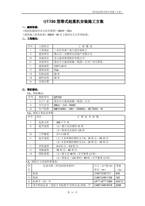
QTZ80型塔式起重机安装施工方案一、编制依据:《建筑机械使用安全技术规程》JGJ33—2001《建筑施工检查标准》JGI59—99及上级的有关文件和标准;二、工程概况:三、塔机情况:四、汽车吊的确定及地址承载验算(附25T汽车吊额定起重表及起升高度曲线表):4.1、从25吨汽车吊参数表中查出该车自重为28.27吨,加辅助工具为30吨。
4.2、当中心水平距(汽车吊与塔吊间)为8米,臂伸到31米时吊重量为5.3吨。
4.3、当中心水平距(汽车吊与塔吊间)为6米,臂伸到25.75米时吊重为7.5吨。
故此确定使用25吨汽车吊吊装该机完全满足要求,因为此时确定汽车吊置放位置与塔机基础中心距为6.5米,基塔初装高度仅为16.4米;本机最重部件仅为4.8吨。
4.4、汽车吊置放位置及地理验算:由于该塔机需装在建筑物的南面纵向13-14轴支付桩上,北为建筑物及临时施工道路和料场;此场地宽约50 米,长约110 米。
从该地试压测量数据证明每平方米承载压力为18吨。
验算:已知⑴地质承载力为18T/㎡;⑵汽车吊自重为30T;⑶塔机部件最大重量为4.8T;⑷25T汽车吊在工作时为4块1㎡的专用液压支腿触地。
计算:⑴此地承载力为:4×1㎡×18T=72T⑵汽车吊在最大工作量时所需此地承载力为;30T+4.8T=34.8T⑶∵72T>34.8T∴此地完全满足工作需要,无需其它辅助措施。
五、安装准备工作:5.1、检查基础表面平整度、地脚螺栓情况及砼强度是否达标。
5.2、对需安装的整机及各部件进行检查,特别是液压系统、金属结构、机构等。
5.3、塔机安装队(具备安装资格认可证)进场前,必须有专项安装施工方案,安装主要人员职责分工明确有安装单位有效资质证。
六、安装作业过程中的注意事项:6.1、塔机安装的基本规定:6.1.1、司机、安装工、起重工必须是劳动部门进行效核取得合格证者;严禁无证操作、安装维修塔机。
6.1.2、安装塔机的全过程必须有专人指挥,严禁无指挥操作。
血液净化进展

单击此处可添加副标题
ⅲ血液系统: ⅴ消化系统: 高粘稠综合征 急性肝功能衰竭 自家免疫性溶血贫血 ⅵ内分泌系统: 血栓性血小板减少性紫癜 甲亢危象 ⅳ神经系统: ⅶ 中毒: 重症肌无力 百枯草 毒蕈碱 多发性硬化 ⅷ 其它 格林巴利综合征 牛皮癣 SLE神经损害
血液透析
01
添加标题
血液透析设备
02
添加标题
透析机
03
添加标题
透析器
04
添加标题
水处理设备
05
添加标题
透析液
06
添加标题
血管通路
短时血液净化: 50年代初和60年代未使用两个1.4-1.8m²Kolff-Travenol蟠管型透析器,血流量200-300ml/min,治疗急性和慢性肾衰,每次4-5小时。 Manji等使血流量达400ml/min,3小时尿素清除率250ml/min,相当于标准透析6小时的溶质清除率率,从而首次证明高血流量可以在短时间内获得满意的溶质清除率。
CRRT名称中英文对照
血泵 肝素泵 滤出液 透析液
CRRT示意图CVVHD
CRRT示意图CVVHF
补液泵 前稀释 后稀释 血泵 肝素泵 滤出液
CRRT示意图CVVHDF
肝素泵
1
输液
2
血泵
3
滤出液 透析液
4
CRRT技术
无辅助循环泵的CRRT 心脏作为动力泵,动脉穿刺或置管建立体外循环 CAVH、CAVHD、CAVHDF 血流量低50~100ml/min 溶质清除率低,尿素氮清除<20L/d,GFR<15ml/min 无需特殊设备,操作简单,耐受性好
04
清除细胞因子、炎症介质?
罗马数字8怎么写

记数方法1、相同的数字连写,所表示的数等于这些数字相加得到的数,如:Ⅲ = 3;2、小的数字在大的数字的右边,所表示的数等于这些数字相加得到的数,如:Ⅷ = 8;Ⅻ = 12;3、小的数字,(限于Ⅰ、X 和C)在大的数字的左边,所表示的数等于大数减小数得到的数,如:Ⅳ= 4;Ⅸ= 9;4、正常使用时,连写的数字重复不得超过三次。
(表盘上的四点钟“IIII”例外)5、在一个数的上面画一条横线,表示这个数扩大1000倍。
注意:1、基本数字Ⅰ、X 、C 中的任何一个,自身连用构成数目,或者放在大数的右边连用构成数目,都不能超过三个;放在大数的左边只能用一个。
2、不能把基本数字V 、L 、D 中的任何一个作为小数放在大数的左边采用相减的方法构成数目;放在大数的右边采用相加的方式构成数目,只能使用一个。
3、V 和X 左边的小数字只能用Ⅰ。
4、L 和C 左边的小数字只能用X。
5、D 和M 左边的小数字只能用C。
6、重复数次:一个罗马数字重复几次,就表示这个数的几倍。
7、右加左减:在较大的罗马数字的右边记上较小的罗马数字,表示大数字加小数字。
在较大的罗马数字的左边记上较小的罗马数字,表示大数字减小数字。
左减的数字有限制,仅限于I、X、C。
比如45不可以写成VL,只能是XLV但是,左减时不可跨越一个位数。
左减数字必须为一位,比如8写成VIII,而非IIX。
右加数字不可连续超过三位,比如14写成XIV,而非XIIII。
(见下方“数码限制”一项。
)8、加线乘千:在罗马数字的上方加上一条横线或者加上下标的Ⅿ,表示将这个数乘以1000,即是原数的1000倍。
同理,如果上方有两条横线,即是原数的1000000倍。
9、数码限制:同一数码最多只能出现三次,如40不可表示为XXXX,而要表示为XL。
例外:由于IV是古罗马神话主神朱庇特(即IVPITER,古罗马字母里没有J和U)的首字,因此有时用IIII代替Ⅳ。
8是4的几倍

8是4的几倍
4的8倍是32,8是4的2倍,2的4倍是8。
分析过程如下:
4的8倍是多少的数学表达式:48=32。
几的4倍是8的数学表达式:8÷4=2。
扩展资料:
整数的乘法法则:
(1)从个位乘起,依次用第二个因数每位上的数去乘第一个因数;
(2)用第二个因数那一位上的数去乘,得数的末位就和第二个因数的那一位对齐;
(3)再把几次乘得的数加起来。
乘法的运算规律:
(1)乘法交换律:ab=ba
(2)乘法结合律:abc=(ab)c=a(bc)
(3)乘法分配律:(a+b)c=ac+bc;(a-b)c=ac-bc
除法:
(1)把一个数平均分成若干份,求其中的一份;
(2)求一个数里有几个另一个数;
(3)已知一个数的几分之几或百分之几是多少求这个数;
(4)求一个数是另一个数的几倍。
除法的法则:
(1)从被除数的高位除起,除数有几位,就看被除数的前几位,如
果不够除,就多看一位。
(2)除到被除数的哪一位,就把商写在哪一位的上面,如果不够除,就在这一位上商0。
(3)每次除得的余数必须比除数小,并在余数右边一位落下被除数
在这一位上的数,再继续除。
8的整数划分

8的整数划分全文共四篇示例,供读者参考第一篇示例:8的整数划分是一个经典的组合数学问题,它指的是将整数8划分成若干个整数之和的方式。
这个问题看似简单,但却涉及到了许多深奥的数学原理和方法。
在这篇文章中,我们将从历史、定义、性质以及计算方法等方面对8的整数划分进行详细的介绍。
我们来了解一下关于整数划分的历史。
整数划分这个概念最早可以追溯到欧几里得的《算术》一书中,他研究了将整数划分成若干个整数之和的问题。
而关于8的整数划分的讨论可以追溯到19世纪,当时的数学家们开始研究将整数8划分成若干个整数之和的方式,并提出了各种计算方法和性质。
在介绍8的整数划分之前,我们先来看一下整数划分的一般定义。
整数划分指的是将一个正整数n拆分成若干个正整数之和的方式,其中各个正整数可以是相同也可以是不同的。
对于整数8而言,它的所有划分方式包括8,7+1,6+2,6+1+1,5+3,5+2+1,5+1+1+1,4+4,4+3+1,4+2+2,4+2+1+1,4+1+1+1+1,3+3+2,3+3+1+1,3+2+2+1,3+2+1+1+1,3+1+1+1+1+1,2+2+2+2。
在这些划分方式中,我们可以发现有些方式是等价的,比如8和1+1+1+1+1+1+1+1就属于同一种划分方式。
这就涉及到了整数划分中的“等价划分”概念。
在整数划分中,如果两种划分方式的每个划分项的数量和数值都相同,那么这两种划分方式就是等价的。
通过等价划分的概念,我们可以排除掉重复的划分方式,从而减少计算的复杂度。
接下来,我们来探讨一下8的整数划分的性质。
我们可以得出结论:8的整数划分总共有22种。
这个结论可以通过计算方法来验证,也可以通过数学理论和推导来证明。
我们可以观察到8的整数划分中,最大的划分项是8,最小的划分项是1。
这个性质在整数划分中是非常常见的,通常会有一个最大划分项和一个最小划分项,中间各种划分项的组合方式则有多种多样。
在8的整数划分中,我们还可以发现几种特殊的整数划分方式。
- 1、下载文档前请自行甄别文档内容的完整性,平台不提供额外的编辑、内容补充、找答案等附加服务。
- 2、"仅部分预览"的文档,不可在线预览部分如存在完整性等问题,可反馈申请退款(可完整预览的文档不适用该条件!)。
- 3、如文档侵犯您的权益,请联系客服反馈,我们会尽快为您处理(人工客服工作时间:9:00-18:30)。
探讨常用糖皮质激素对0.4%罗哌卡因锁骨上臂丛神经阻滞麻醉效
果的影响
糖皮质激素是一类常用的抗炎药物,具有抗炎、免疫抑制、抗过敏等作用。
在临床上,糖皮质激素常被用于治疗各种炎症性疾病,如过敏性疾病、风湿性疾病、关节炎等。
而罗
哌卡因是一种局部麻醉药,常被用于各种手术和神经阻滞麻醉。
本文旨在探讨常用糖皮质
激素对0.4%罗哌卡因锁骨上臂丛神经阻滞麻醉效果的影响。
一、研究背景
神经阻滞麻醉是一种通过给药物注射到神经周围使神经传导受阻的麻醉方式。
锁骨上
臂丛神经阻滞是一种常用的神经阻滞麻醉方法,用于上肢手术和镇痛。
而罗哌卡因是一种
局部麻醉药,能有效地抑制神经传导,达到麻醉的目的。
糖皮质激素具有抗炎和免疫抑制
作用,一些研究表明,糖皮质激素与局部麻醉药合用可以提高麻醉效果,延长麻醉时间。
但同时也有研究显示,糖皮质激素在神经阻滞麻醉中的作用并不明确,有些研究指出,糖
皮质激素可能会影响局部麻醉药的作用,降低神经阻滞麻醉的效果。
二、研究内容
本研究旨在探讨常用糖皮质激素对0.4%罗哌卡因锁骨上臂丛神经阻滞麻醉效果的影响。
具体研究内容包括:
1. 确定研究对象:选择300名需要进行锁骨上臂丛神经阻滞麻醉的患者作为研究对象,年龄在18-65岁之间,排除有肝肾功能不全、心脏病、神经系统疾病等情况的患者。
2. 随机分组:将研究对象随机分为实验组和对照组,每组150人。
实验组给予罗哌卡因和糖皮质激素联合使用,对照组给予罗哌卡因单独使用。
3. 观察指标:观察两组患者的麻醉效果,包括起效时间、麻醉深度、麻醉持续时间、术后镇痛效果等指标。
4. 数据统计分析:采用统计学方法对观察数据进行分析,比较两组患者的麻醉效果,判断糖皮质激素对罗哌卡因锁骨上臂丛神经阻滞麻醉效果的影响。
三、研究意义
本研究的意义在于能够探讨糖皮质激素对罗哌卡因锁骨上臂丛神经阻滞麻醉效果的影响,为临床手术和镇痛提供更为有效和安全的途径。
如果实验证明糖皮质激素对罗哌卡因
的麻醉效果有积极的促进作用,将为临床手术提供更为有效的麻醉方式。
反之,如果实验
证实糖皮质激素对罗哌卡因麻醉效果影响不大,也将为临床术后镇痛提供重要参考。
五、预期结果
根据研究内容和方法,预期结果可能有以下几种情况:
1. 实验组患者的麻醉效果明显优于对照组患者,糖皮质激素能够有效地提高罗哌卡因的麻醉效果。
2. 实验组患者的麻醉效果与对照组患者相似,糖皮质激素对罗哌卡因的麻醉效果影响不大。
3. 实验组患者的麻醉效果明显差于对照组患者,糖皮质激素对罗哌卡因的麻醉效果产生负面影响。