子午线轮胎有限元分析第5讲轮胎胶料有限元分析的材料参数实验
轮胎结构有限元分析应用于子午线轮胎帘线受力特性的研究
(! ) 冠带层
-5, -5. /-5. /-5, /-5# #(0(*+ ),+ )(+
弧长 1 22
.,-
.%-
.*-
胎体 (" ) 图(
, . /. /, /# $*(*+ ),+ )(+
弧长 1 22
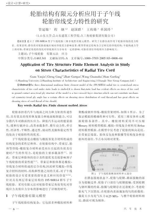
!" 方向帘线剪应力分布
具有重要的实际指导意义。
-!) -+)
/"" ," +" *" !" " 4/," 4/!" 4+" " +" +,) -!) -+) /!" /,"
弧长 0 33
."
/!"
/#"
/,"
(( ) 胎体 图! 沿 ")截面子午向各层帘线应力分布
圆周向位置 ( 0 ))
(& ) 第二带束层
!""# 年
第$期
— - —
・ 设计 ・ 计算 ・ 研究 ・
[#, $] 午线轮胎的质量性能 。带束层和胎体都是橡胶 /
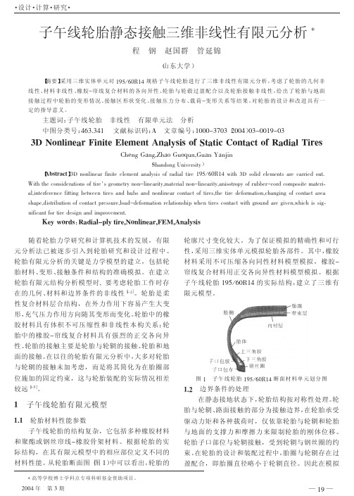
如图 ! 所示。为了 聚酯或钢丝帘线/橡胶骨架材料, 保证模拟的精确性和可行性,采用三维实体单元模 拟轮胎各部件。其中,橡胶材料采用不可压缩 橡胶/帘线复合材料用 +:S3E T==4:H 材料模型模拟, 材料模型模拟。 在模型中仅考虑了轮胎的纵向花纹。 在带束层端部、胎体反包处和胎圈等结构复杂和易 损坏的部位, 节点布局相对密集。
(& ) 图%
子午线轮胎静态接触三维非线性有限元分析
・ 设计 ・ 计算 ・ 研究 ・ 善接地压力分布状况, 使之分布均匀合理, 将直接影 响到轮胎的使用性能。
图,
带束层端点圆周向应力分布
( 接地横轴接触压力分布 %)
图 ."
胎体反包处圆周向应力分布
由图 , 、 图 ." 可以看出 , 带束层端点和胎体反 包处圆周向应力分布在接地区域呈相反趋势,带束
・ 设计 ・ 计算 ・ 研究 ・
子午线轮胎静态接触三维非线性有限元分析 %
程 钢 赵国群 管延锦
( 山东大学)
【 摘要】 采用三维实体单元对 &’( ) *"+&# 规格子午线轮胎进行了三维非线性有限元分析, 考虑了轮胎的几何非 轮胎与轮毂过盈配合以及轮胎接触非线性, 给出了轮胎与地面 线性、 材料非线性、 橡胶 , 帘线复合材料的各向异性、 对轮胎的设计和改进具有一 接触过程中轮胎的变形情况、 接触区形状变化、 接触压力 分 布 、 载 荷,变 形 关 系 等 结 果 , 定的指导意义。
[ $Q(]
图&
子午线轮胎 &’( ) *"+&# 断面材料单元划分图
。
@Байду номын сангаасB
边界条件的处理 在静态接地状态下, 轮胎结构按对称性处理。 轮
@
@A@
子午线轮胎有限元模型
轮胎材料性能参数 子午线轮胎的结构复杂,它包括多种橡胶材料
胎与轮辋、 路面接触的部分为接触边界, 在轮胎承受 驱动力矩和各种载荷时,仅依靠轮胎与轮辋和轮胎 与地面的支撑力和摩擦力来限制轮胎的刚体位移。 轮胎子口部位与轮辋接触,受到轮辋与钢丝圈的约 束。 在轮胎的设计和装配过程中, 胎圈与轮辋存在过 盈配合,即胎圈直径略小于轮辋直径。因此在模拟
胎面胶对全钢子午线轮胎滚动阻力影响的有限元分析

“双向解耦”的迭代求解法(以下简称双向迭代解 法)。所谓双向迭代解法即为依次独立求解应力应 变 场 和 温 度 场 两 个 边 值 问 题,并 通 过 温 度 迭 代 来计算应力-应变场和温度场之间的互相影响。 双向迭代解法的提出使有限元方法真正成为求解 轮胎温度场问题的有效工具。
36%;对于采用低滚动阻力配方胎面胶的轮胎,胎
面胶对轮胎滚动阻力的贡献率显著减小至21%。
采用传统配方胎面胶和低滚动阻力配方胎面
胶的轮胎的滚动阻力仿真结果对比如图3所示。
从 图 3 可 以 看 出,在 优 化 胎 面 胶 配 方 后,轮 胎
ۘᑚ֖ Ӊ࣊ Ю᛭ࡎ 6% 6% ᑁͳ
7%
ᑁ᭦ᑚ 36%
ࣛోࡎ 9%
表1 轮胎滚动阻力的仿真结果和实测结果
项 目 滚动阻力系数/(N·kN-1) 传统配方 低滚动阻力配方 滚动阻力标签等级 传统配方 低滚动阻力配方
仿真结果
5. 265 4. 755
C B
实测结果
4. 265 3. 970
B A
从表1可以看出,尽管仿真结果与实测结果有
一 定 误 差,但 不 论 是 仿 真 结 果 还 是 实 测 结 果 都 说
[11] 陈秋红. 载重子午线轮胎稳态温度场分析[D]. 上海:东华大学, 2008.
[12] 吴福麒. 轮胎稳态滚动温度场的有限元分析[D]. 合肥:中国科技 大学,2009.
[13] 王国林,陈晨,周海超,等. 胎面与胎体间接触特性对轮胎滚动阻 力影响的研究[J]. 橡胶工业,2020,67(6):403-409.
[4] Yavari B,Tworzydlo W W,Bass J M. A Thermomechanical Model to Predict the Temperature Distribution of Steady State Rolling Tires[J]. Tire Science and Technology,1993,21(3):163-178.
全钢载重子午线轮胎侧偏特性有限元分析

全钢载重子午线轮胎侧偏特性有限元分析发布时间:2021-08-09T15:34:50.137Z 来源:《中国科技信息》2021年9月中作者:姜敬如杨丽张鹏飞[导读] 汽车对地面的作用是通过轮胎实现的,轮胎的力学特性直接影响车辆的操纵性、平顺性和安全性等性能。
汽车的操纵稳定性很大程度上取决于轮胎的侧偏特性,其已成为各汽车厂家和轮胎生产企业研究和分析的重点。
八亿橡胶有限责任公司姜敬如杨丽张鹏飞山东省枣庄市 277000摘要:汽车对地面的作用是通过轮胎实现的,轮胎的力学特性直接影响车辆的操纵性、平顺性和安全性等性能。
汽车的操纵稳定性很大程度上取决于轮胎的侧偏特性,其已成为各汽车厂家和轮胎生产企业研究和分析的重点。
在汽车行驶过程中,由于路面的侧向倾斜、转弯时的离心力等因素,使车轮的运动方向偏离其中心,此时车轮的旋转平面与行驶方向的夹角称为侧偏角。
传统的试验方法是研究轮胎侧偏特性的重要手段,黄舸舸等通过常规试验研究了带束层结构对轮胎侧偏特性的影响。
近年来,随着计算机技术的飞速发展和有限元商用分析软件的不断完善,有限元仿真分析方法开始应用于轮胎侧偏特性的研究。
关键词:全钢载重子午线轮胎;侧偏特性;侧向力;回正力矩;有限元分析引言轮胎是汽车的重要组成部件,是橡胶工业重要的产品。
轮胎的主要功能是支承负荷,向地面传递制动力、驱动力和转向力,以及缓冲减振,车辆实现各种运动的外力大部分都是由轮胎与路面的相互作用产生的。
轮胎对汽车性能具有十分重要的影响,车辆的许多重要性能都与轮胎的力学特性有关,如车辆的操纵稳定性、行驶与制动的安全性、车辆动力性与通过性等,而且还影响着汽车的环保性能和运输效率,这些性能的改善都依赖于对轮胎力学特性的研究。
因此轮胎力学特性的研究是车辆动力学分析和研究的基础.1全钢载重子午线轮胎的结构橡胶材料属超弹性材料,具有近似体积不可压缩性和非线性本构关系,它的力学行为对温度、环境、应变历史、加载的速率都非常敏感,这样使得描述橡胶的行为变得更为复杂。
有限元分析考评实例:子午线轮胎断面测试和轮胎有限元模型的修正-李兵-200706

有限元分析考评实例:子午线轮胎断面测试和轮胎有限元模型的修正李兵,李子然,夏源明中国科学技术大学力学与机械工程系,合肥 230027摘要:在考评使用ABAQUS 软件给出的某种子午线轮胎的有限元分析结果时发现,轮胎的负荷-下沉量曲线以及径向刚度的计算结果与试验结果比较吻合,但接地印痕形状和接地压力分布的计算结果与试验结果相差很大。
为了找出问题所在,针对实际轮胎进行了轮廓测试和截断面分析,以检验轮胎实际构型与设计构型是否存在较大差别;结果表明,轮胎内轮廓曲线以及带束层帘线角分布的实际情况与设计参数均差别较大。
根据测试结果对有限元模型的初始构型进行了修正,修正后模型的接地压力分布计算结果明显改善,与实验测量结果具有非常一致的特征。
关键词:子午线轮胎 有限元分析 有限元模型 考评 断面测试1. 研究背景在使用试验结果对使用ABAQUS 软件进行的某种规格子午线轮胎的有限元分析结果进行考评时发现,轮胎的负荷-下沉量曲线以及径向刚度∗v e r t i c a l d e f o r m a t i o n (m m )load (N)的计算结果与试验结果比较吻合(如图1所示),但接地印痕和压力分布的计算结果与试验结果相差很大(如图2所示),接地形状的计算结果接近圆形,测试结果则接近方形;胎肩部接地长度的计算结果小于测试结果,在胎冠中部接地长度的计算结果则大于测试结果。
在检验了模拟方法和计算方法本身的合理性后,使用计及复杂胎面花纹的轮胎模型[1]进行了分析,但上述差异仍然明显存在。
也就是说,有限图1 载荷-位移曲线的测试结果和计算结果(气压为180kpa )∗注:图1和图2中的试验结果在PL-2003轮胎综合试验机上测得。
在试验前使用测力环和游标卡尺对该试验机的力量和位移测量结果进行了校正,以确保试验数据的可靠性。
(a) 试验结果 (b) 忽略横向花纹轮胎模型的计算结果 (c) 计及复杂花纹轮胎模型的计算结果图2 接地压力的测试结果和计算结果(气压为0.18MPa ,负荷为4000N )实际上,轮胎经过包括硫化过程在内的复杂的工艺流程加工而成[2],这些复杂的工艺流程可能导致成品轮胎的实际构型与设计构型有所不同。
全钢子午线轮胎胎圈耐久性能试验方法有限元验证
理论•研究第10期全钢子午线轮胎胎圈耐久性能试验方法有限元验证张伟伟,刘岩,罗哲[浦林成山(青岛)工业研究设计有限公司,山东青岛266000]摘要:对12R22.5无内胎和12.00R20有内胎全钢子午线轮胎进行有限元仿真分析,分别对有、无胎面两种模型的轮胎胎圈部位进行受力分析,对比胎体反包端点应变能密度。
结果表明,磨掉胎面轮胎的胎圈部位受力情况与正常轮胎相当,因此磨掉胎面再进行胎圈耐久性能试验能够更有效地反映正常轮胎的胎圈受力情况。
关键词:全钢子午线轮胎;胎圈;耐久性能;无胎面;有限元分析;应变能密度中图分类号:U463.341+.3;O241.82文章编号:2095-5448(2019)10-0557-03文献标志码:A DOI:10.12137/j.issn.2095-5448.2019.10.0557轮胎耐久性能是室内轮胎标准检验项目之一,是与轮胎安全性相关的强制性试验项目。
一般在直径为1.7m的试验转鼓上检验轮胎耐久性能,只有耐久性能满足要求的轮胎才能进入市场“叫当按照国家标准耐久性能试验方法进行试验时,轮胎胎肩往往会早于胎圈损坏这是由于胎面胶较厚,胎肩部位因变形产生的热量不断积累且散热较慢而导致提前损坏,发生这种情况将无法评估胎圈的耐久性能。
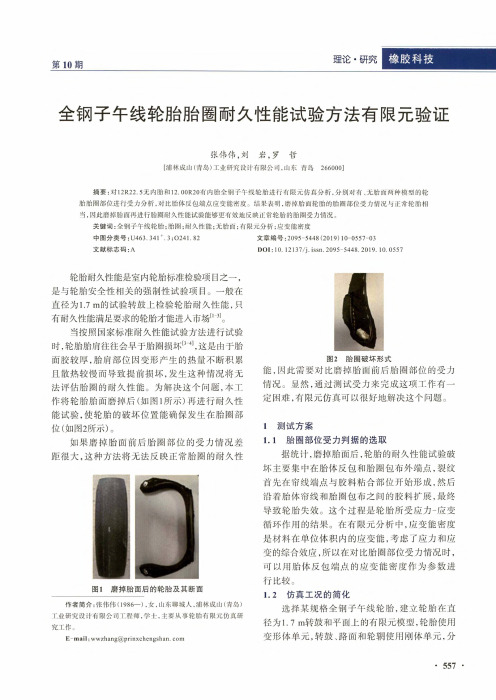
为解决这个问题,本工作将轮胎胎面磨掉后(如图1所示)再进行耐久性能试验,使轮胎的破坏位置能确保发生在胎圈部位(如图2所示)。
如果磨掉胎面前后胎圈部位的受力情况差距很大,这种方法将无法反映正常胎圈的耐久性图1磨掉胎面后的轮胎及其断面作者简介:张伟伟(1986-),女,山东聊城人.浦林成山(青岛)工业研究设计有限公司工程师.学士.主要从事轮胎有限元仿真研究工作。
E-mail:wwzhang@图2胎圈破坏形式能,因此需要对比磨掉胎面前后胎圈部位的受力情况。
显然,通过测试受力来完成这项工作有一定困难,有限元仿真可以很好地解决这个问题。
1测试方案1.1胎圈部位受力判据的选取据统计,磨掉胎面后,轮胎的耐久性能试验破坏主要集中在胎体反包和胎圈包布外端点,裂纹首先在帘线端点与胶料粘合部位开始形成,然后沿着胎体帘线和胎圈包布之间的胶料扩展,最终导致轮胎失效。
全钢载重子午线轮胎侧偏特性有限元分析
全钢载重子午线轮胎侧偏特性有限元分析钱瑞瑾,程 昊(双钱集团上海轮胎研究所有限公司,上海 200245)摘要:以275/70R22.5 RT606全钢载重子午线轮胎为研究对象,运用有限元分析软件TYABAS 和Abaqus 建立轮胎侧偏特性分析有限元模型,并研究不同负荷的稳态滚动条件下,侧向力和回正力矩随侧偏角的变化规律。
结果表明:在单一垂直负荷下,随着侧偏角的增大,侧向力的绝对值逐渐增大,当侧偏角为-5°和5°时,回正力矩分别达到极小值和极大值;在同一侧偏角下,随着负荷的增大,侧向力的绝对值逐渐增大。
侧偏刚度仿真结果与试验结果一致,验证了仿真分析方法的有效性。
关键词:全钢载重子午线轮胎;侧偏特性;侧向力;回正力矩;有限元分析;仿真分析中图分类号:U463.341+.3/.6;O241.82 文章编号:1006-8171(2021)03-0143-05文献标志码:A DOI :10.12135/j.issn.1006-8171.2021.03.0143汽车对地面的作用是通过轮胎实现的,轮胎的力学特性直接影响车辆的操纵性、平顺性和安全性等性能。
汽车的操纵稳定性很大程度上取决于轮胎的侧偏特性,其已成为各汽车厂家和轮胎生产企业研究和分析的重点。
在汽车行驶过程中,由于路面的侧向倾斜、转弯时的离心力等因素,使车轮的运动方向偏离其中心,此时车轮的旋转平面与行驶方向的夹角称为侧偏角,如图1所示。
传统的试验方法是研究轮胎侧偏特性的重要手段,黄舸舸等[1]通过常规试验研究了带束层结构对轮胎侧偏特性的影响。
近年来,随着计算机技术的飞速发展和有限元商用分析软件的不断完善,有限元仿真分析方法开始应用于轮胎侧偏特性的研究[2-10]。
图1 车轮侧偏示意本工作以275/70R22.5 RT606全钢载重子午线轮胎为研究对象,运用哈尔滨工业大学复合材料与结构研究所开发的轮胎专用有限元分析软件TYABAS 建立轮胎二维和三维有限元分析模型,在Abaqus 软件中建立不同侧偏角的轮胎侧偏特性分析有限元模型,使用隐式分析方法进行仿真分 析[11-18],并对计算结果进行处理,得到轮胎的侧向力和回正力矩等数据。
子午线轮胎稳态滚动有限元分析
子午线轮胎稳态滚动有限元分析
尹伟奇;姚振汉;薛小香;洪宗跃
【期刊名称】《橡胶工业》
【年(卷),期】2005(52)7
【摘要】以MSC.Marc软件为平台,建立子午线轮胎的三维非线性稳态滚动有限元模型.在模型计算中,考虑了轮胎的静态载荷施加过程、自由滚动过程、完全刹车滑动过程、防抱死刹车过程和牵引过程,得到了轮胎接地面的接触应力分布情况及轮胎牵引力与转速之间的关系等结果,有利于进一步了解轮胎的动态性能.
【总页数】7页(P389-395)
【作者】尹伟奇;姚振汉;薛小香;洪宗跃
【作者单位】清华大学,工程力学系,北京,100084;清华大学,工程力学系,北
京,100084;清华大学,工程力学系,北京,100084;北京橡胶工业研究设计院,北
京,100039
【正文语种】中文
【中图分类】TQ336.1+1;O241.82
【相关文献】
1.带复杂花纹的子午线轮胎建模方法及其稳态滚动的有限元分析 [J], 蒋丰璘
2.子午线轮胎稳态滚动的有限元分析 [J], 蒋丰璘
3.子午线轮胎有限元分析第8讲子午线轮胎稳态滚动分析 [J], 洪宗跃;吴桂忠
4.子午线轮胎稳态滚动侧偏特性有限元分析 [J], 王伟;许喆;赵树高
5.无内胎全钢轻型载重子午线轮胎稳态滚动温度场有限元分析 [J], 王学瑞;王泽君;王友善
因版权原因,仅展示原文概要,查看原文内容请购买。
子午线轮胎用原材料性能要求及成品检测
子午线轮胎用原材料性能要求及成品检测目录1 对原材料质量首要的要求2 子午线轮胎用天然橡胶3 子午线轮胎用合成橡胶4 子午线轮胎半成品部件的性能要求5 子午线轮胎的成品检测1 对原材料质量首要的要求子午线轮胎的生产,与斜交轮胎相比,除要求生产厂的装备、工艺控制、生产管理和测试水平要有较大提高外,对所用原材料品种、质量控制和应用技术也提出了更为严格的要求。
使用性能稳定、均匀一致的高质量原材料,是生产高质量子午线轮胎的重要保证条件之一。
2 子午线轮胎用天然橡胶2.1总的要求及包装(1) 胶块应无木材、金属、纤维、石料等之类的外来物。
(2) 橡胶必须基本上无模压,但表面上的干燥模痕不受此限。
橡胶中离散的斑点虽无限制,但不容许有“原始的”(未干燥)橡胶。
(3) 颜色等级鉴别(4) 每一块胶用0.4 cm厚的聚乙烯塑料布包装。
每块胶周围放白色的聚乙烯塑料布条,用红色字母写上等级号。
包装好的胶块放在适合的托架上,每层用0.08/0.10mm厚的红色聚乙烯塑料布隔开。
注:在某些使用开炼机塑炼的地方,胶块需要用0.08/0.10mm厚的聚乙烯塑料布包装,以便卸袋,在某些情况下,如果适合,也可以要求用滑石粉处理胶块。
(5) 每一胶块重——33.3 kg(6) 胶块规格——680mmX 340mmX 150/180mm(7) 标准托架规格——1425mmX1100mm(8) 收到的橡胶必须无由于非橡胶组合分(例如篦麻油)腐烂造成的有害气味。
*聚乙烯要求符合下列技术条件:熔点105℃以下,比重0.92和溶解指数最小2.0。
2.2标准橡胶的规格子午线轮胎最常用的天然橡胶是标准橡胶TSR 10和TSR 20。
天然橡胶由于综合性能良好,可以单独使用,制作各种橡胶制品,也可与其他合成橡胶并用,以改进其他橡胶的性能,如成型粘性,拉伸强度,撕裂强度等,从而提高橡胶制品的全面性能。
天然橡胶生胶强度和自粘性好,胎胚形状易保持。
轮胎越大,天然橡胶比例越高。
轮胎有限元分析之材料测试
Material Test for FEAContent1、Elastomer (hyperelastic) Characterization (2)1.1 Typical Dense Elastomer Experiments (2)1.2 Specimen Preparation (6)1.3 Elastomer Testing Services (6)2 Plastic Characterization (7)2.1 Typical Plastic Experiments: (8)2.2 Plastic Specimen Preparation (12)3 Elastomeric Sponge (foam) Characterization (13)3.1 Introduction (13)3.2 Typical Foam Elastomer Experiments: (13)4 Fabric Testing (16)4.1 Introduction (16)4.2 Typical Plastic Experiments: (16)5 Wire Testing (17)6 Durability and Crack Growth Testing (18)6.1 Introduction (18)6.2 Tear and Crack Growth Experiments: (18)7 Friction Measurements (20)7.1 Introduction (20)7.2 Typical Plastic Experiments: (20)8 High Strain Rate Experiments (21)8.1 Introduction (22)8.2 Typical High Strain Rate Experiments: (22)9 Long Term Creep and Stress Relaxation Tests (24)9.2 Experiments: (25)10 Thermal Properties Measurements (26)10.1 Introduction (26)10.2 This section is divided into sections as follows: (26)11 Vibration and Viscoelastic Experiments (27)11.1 Introduction (27)11.2 This section is divided into sections as follows: (27)基于有限元分析的关于高分子材料的基础实验情况全简介byhyj1、Elastomer (hyperelastic) CharacterizationIntroduction:The analysis of elastomers in finite element analysis often require the use of hyperelastic material models. These models require that material specimens of the subject material be stretched and stress-strain data collected. Most hyperelastic models perform better if multiple states of strain are represented. Elastomers should be characterized at the temperature of the application.Multiple Strain StatesThere are 3 strain states which are particularly useful in characterizing dense elastomers. They are simple tension, pure shear and equal biaxial extension. If the elastomer is confined in its application and the compressible nature of the elastomer is a concern, a volumetric compression experiment (bulk modulus) may also be advisable. This section is divided into experimental sections as follows:1.1 Typical Dense Elastomer Experiments◆Simple Tension◆Pure Shear◆Equal Biaxial Extension◆Volumetric Compression◆Simple Compression◆Elastomer Specimen Preparation1.1.1 Simple TensionSimple tension experiments are very popular for elastomers. There are several standards for the testing of elastomers in tension. However, the experimental requirements for analysis are somewhat different than most standardized test methods. The most significant requirement is that in order to achieve a state of pure tensile strain, the specimen must be much longer in the direction of stretching than in the width and thickness dimensions. The objective is to create an experiment where there is no lateral constraint to specimen thinning.Simple Tension Test Specimen OutlineSimple Tension Test in an Environmental Chamber Fitted with Optical Glass for use with a LaserExtensometer1.1.2 Planar Tension (Pure Shear)The pure shear experiment used for analysis is not what most of us would expect. The experiment appears at first glance to be nothing more than a very wide tensile test. However, because the material is nearly incompressible, a state of pure shear exists in the specimen at a 45 degree angle to the stretching direction. The most significant aspect of the specimen is that it is much shorter in the direction of stretching than the width. The objective is to create an experiment where the specimen is perfectly constrained in the lateral direction such that all specimen thinning occurs in the thickness direction.Planar Tension Test Specimen OutlinePlanar Tension (Pure Shear ) with Laser Extensometer1.1.3 Equal Biaxial ExtensionFor incompressible or nearly incompressible materials, equal biaxial extension of a specimen creates a state of strain equivalent to pure compression.though the actual experiment is more complex than the simple compression experiment, a pure state of strain can be achieved which will result in a more accurate material model.Equal Biaxial Test SpecimenEqual Biaxial Extension Experiment1.1.4 Volumetric Compression (Bulk Modulus)V olumetric compression is an experiment where the compressibility of the material is examined. In this experiment, a cylindrical specimen is constrained in a fixture and compressed . The actual displacement during compression is very small and great care must be taken to measure only the specimen compliance and not the stiffness of the instrument itself. The initial slope of the resulting stress-strain function is the bulk modulus. This value is typically 2-3 orders of magnitude greater than the shear modulus for dense elastomers.V olumetric Compression Experiment1.1.5 Simple CompressionThe compression experiment is also a popular test for elastomers. When testing for analysis, pure states of strain are desired and this is especially difficult to achieve experimentally in compression for dense materials. However, for foam materials, the error due to friction between the specimen and platen is not as significant.Simple Compression Test1.2 Specimen PreparationMaterial testing experiments on elastomers typically require sheets of elastomer from which test specimens are die cut. If elastomer sheets aren't available, sometimes sheets can be skived from thicker slabs or actual parts.Specimen Shapes Stamped from SheetsBandknife Slicing System to Create Rubber Sheets From Bulk Pieces1.3 Elastomer Testing ServicesThe objective of the testing services is to define the basic material properties of elastomeric materials.1.3.1. Basic Hyperelastic Properties3 simple tension specimens, 3 planar tension specimens and 3 equal biaxial specimens are cut from the provided slabs. Or for foam materials, 3 simple tension specimens, 3 simple shear specimens and 3 simple compression specimens are cut from provided slabs. The specimens are loaded slowly between zero force and a user defined stretch level for 5 loadings and unloadings at up to4 maximum strain levels so as to examine the initial stress strain behavior and the “stabilized” stress strain behavior at each of the maximum strain conditions. (5 slabs, 150 mm by 150 mm by 1.0 to 2.0 mm thick are required for each temperature condition)1.3.2 Short Term Stress Relaxation PropertiesStress and time data is collected continuously at a single set strain level for 2000 seconds. 3 specimens are tested. Simple tension, planar tension, compression or equal biaxial specimens may be used. This test can be expanded to include multiple strain levels, and multiple types of specimen. As such, it may replace the basic hyperelastic properties plus standard short-term relaxation properties tests in some material models. (Two standard 150 mm by 150 mm by 1.0 to 2.0 mm thick test slabs of the material is required for each temperature or strain condition, in either a standard or an expanded short-term stress relaxation test).1.3.3. Volumetric CompressionA specimen is fully constrained and compressed for the purpose of determining the Bulk Modulus of the material. 6.35 mm diameter disks are cut from standard slabs and stacked. The initial slope of this curve is the Bulk Modulus.1.3.3. FrictionTo measure the aforementioned proportionally factor or coefficient of friction, a 50 mm by 100 mm sled with one material is dragged against a larger second material. Rubber and plastic materials may be sensitive to the normal pressure between the surfaces. The normal pressure is modified by resting weights on the sled.Required Materials:◆Material sheets or plaques greater than 50mm x 150mm for the sled.◆Materials greater than 100mm x 500mm for the base.1.3.4. Static TearingThe static tearing experiment is a meaningful way to examine the failure of an elastomer in tearing.A sharp cut is introduced into a planar tension specimen and the specimen is stretched until failure. Failure stress, failure strain and total tearing energy are reported.1.3.5. Thermal PropertiesThermal conductivity, thermal diffusivity and specific heat are determined using the transient plane source method (HotDisk™). One standard 150 mm by 150 mm test slab (more than 1 mm thick) of the material is required for each temperature condition.Thermal expansion is determined by examining the dimensional change in a material specimen as temperature changes using a Perkin-Elmer Diamond TMA instrument.2 Plastic CharacterizationIntroductionThe physical testing of plastic materials for the purpose of defining material constitutive models in finite element analysis can be very simple or incredibly complex depending on the objective of the analysis. Linear analysis of structural parts is routinely performed using only a couple simple parameters. More complex analysis may involve elevated temperatures, severe plastic deformation and strain rate sensitivity requiring customized material model development and rigorous experimentation.Plastic Tensile Test DataThere are a few experiments that are particularly useful in characterizing plastics for analysis. They are simple tension with transverse strain measurement for elasticity and Poisson's ratio determination, simple load and unload experiment to separate the plastic and elastic strain components and thermal expansion as a function of temperature. Several of these experiments are outlined below.2.1 Typical Plastic Experiments:◆Tensile Test◆Tensile Test with Transverse Strain Measurement◆Loading and Unloading Experiments◆Short Term Creep Experiment◆Shear Test◆Plastic Film Experiment◆Compression⏹Plastic Specimen Preparation2.1.1 Tensile TestThe tensile test is performed by straining a plastic specimen in one direction such that the sides if the specimen are free to contract. The region of interest is the narrowed section where the desired state of strain is achieved. Basic parameters derived from a tensile stress-strain curve are the initial material stiffness (Young's Modulus), the material yielding point and the failure stress and failure strain.Various Tensile Test SpecimensTensile Test Specimen with an Axial Extensometer Mounted2.1.2 Tensile Test with Transverse Strain MeasurementTransverse strain is sometimes measured in the modulus region in combination with axial strain such that the ratio of transverse strain to axial strain may be determined. This slope is the Poi sson’s ratio and is a measure of material compressibility. Like low strain axial measurements, low strain transverse measurements are typically made with a clip-on strain gage style extensometer but may also be made with other high resolution devices.Tensile Specimen with Both Axial and Transverse Strain Extensometers2.1.3 Loading and Unloading Strain MeasurementsIn general, yielding is the the region where the contribution of plastic strain (or permanent strain) becomes a significant portion of total strain. Many plastics are complex. There may not be a significant elastic only region at all. Plastic deformation may appear at very small strain values. A more accurate way to determine the yield point is by unloading the specimen. This requires loading a series of virgin specimens to incrementally increasing strain levels. Understanding the contribution of plastic strain to the total strain is critical to predicting how a plastic will load and unload in an application.Typical Load-unload Sequence for a Given Strain Level2.1.4 Short Term Creep ExperimentAs a stress is applied to plastic, the material will strain. If the stress is held constant, the plastic will continue to strain. This is behavior is creep or viscous behavior. Combined with elasticity, we have viscoelastic behavior. At small resulting strains over relatively short times, the release of the stress on the material will result in the material returning to its original shape. At largerstrains or longer times, release of the stress will likely reveal a permanently deformed plastic.Creep Experiment Using an In-plane Compression Fixture2.1.5 Shear TestThe shear state of strain can be important an important addition to the fitting of a multi-axial material model. Shear tests for plastics include various ‘notch’ based experiments including the Arcan and Isopescu specimen style. The shear experiment can provide meaningful data across a wide range of material stiffnesses and a broad strain range. The region where the desired strain state occurs in the shear specimen tends to be small and some assumptions about the transfer of force through the region are required.Plastic Shearing Fixture2.1.6 Plastic Film ExperimentTesting plastic film requires low force load cells and low mass gripping systems. Since contact with the material will alter the measurement, non-contacting laser or image based strain systemsare employed.Plastic Film Experiment with Video Strain Measurement2.1.7 CompressionThe compression test is a challenging experiment in that tall specimens can create an unstable loading condition and short specimens create a constrained loading condition. In any case, direct measurement of platen displacement is required for accurate strain measurement.Compression Platens with a Capacitive Strain Sensor Installed2.2 Plastic Specimen PreparationMaterial testing experiments on plastic materials often requires test specimens to be cut from actual parts or plaques. The shop at Axel is able to cut and machine specimens in various ISO, ASTM and custom shapes based on the application.Typical Plastic Tensile Test Specimen ShapesOnsrud Router System for Cutting Specimens from Plaques3 Elastomeric Sponge (foam) Characterization3.1 IntroductionThe analysis of elastomeric sponge materials in finite element analysis sometimes require the use of hyperelastic material models, sometimes require the use of special sponge models and sometimes may be adequately modeled with simplistic spring models. The defining factors are the extent to which the sponge is compressible and the extent to which the foam is compressed in the application. Most complex material models benefit from experimental data in more than one state of strain. If the sponge elastomer is going to be be modeled as a dense elastomer, the basic simple tension, planar tension and equal biaxial test data sets described in the elastomer section may be appropriate. Other experiments that may prove helpful are listed below.There are 3 strain states which are particularly useful in characterizing sponge (foam) elastomers. They are simple tension with lateral strain measurements, simple shear and simple compression.3.2 Typical Foam Elastomer Experiments:◆ Simple Compression◆ Simple Shear◆ Tension with Lateral Strain MeasurementMany Types of Sponge and Foam Materials3.2.1 Simple CompressionThe compression experiment is also a popular test for elastomers. When testing for analysis, pure states of strain are desired and this is especially difficult to achieve experimentally in compression for dense materials. However, for foam materials, the error due to friction between the specimen and platen is not as significant. Often, the only experiment needed is a simple compression test.Soft Open Cell Elastomers Foam in Compression3.2.2 Simple ShearThe simple shear experiment is ideal for soft elastomer foam materials where it is often possible to bond or glue the specimen to fixtures.Simple Shear Test SchematicThin Closed Cell Foam Rubber in Simple Shear3.2.3 Tension with Lateral Strain MeasurementThe simple tension experiment for foam elastomers is made somewhat more complex with the addition of lateral strain measurement. This is necessary because the relationship between axial and lateral strain is needed.Foam Strip in Tension with Lateral and Axial Strain Measurement using a Video System4 Fabric Testing4.1 IntroductionTesting of woven fabrics for the purpose of defining material constitutive models in finite element analysis is generally about defining the overall behavior of the fabric so as the smear the detailed interactions between the individual fibers. Basic measurements are made for woven materials in tension and variations are made for specific material models relating to products such as air bags or rubber embedded fabric layers.At Axel, most fabric experiments involve wide specimens and the using of imaging to track displacement points on the specimen surface. From these measurements we extract an effective modulus or Poisson's ratio in the warp, weft or 45 degree orientations.4.2 Typical Plastic Experiments:◆ Fabric Tensile Test with Imaging◆ Fabric Specimen PreparationWoven Fabric with Displacement Markers4.2.1 Fabric Tensile Test with ImagingThe tensile test is performed by straining the fabric in one direction such that the sides if thespecimen are free to contract. The geometry and orientation of the fabric are critical parameters and the region of interest is typically in a region away from the gripping.Woven Fabric with Imaging System and Test Frame4.2.2 Fabric Specimen PreparationPreparing the test specimens of woven fabrics can be very tricky. A simple yet specialized cutting system is in place to help with this task.Cutting System for Preparing Fabric Test Specimens5 Wire TestingStructural testing of fine wire for the purpose of obtaining static stress and strain data or cyclic fatigue data can be challenging. Careful gripping and strain measurement are critical parameters for success.Physical Test Results from Load and Unload Straining of a Shape Memory Alloy Wire at 37CWire Specimen with Optical Strain Measurement Tags6 Durability and Crack Growth Testing6.1 IntroductionFailure in rubber components is difficult to understand. The strain at failure in a tensile test can be at several hundred percent yet the parts in service can fail at strains that are only a fraction of the tensile failure. This may be because cracks that already exist or cracks to initiate and grow and cause a part failure. A couple of experiments that help understand these issues follow.6.2 Tear and Crack Growth Experiments:◆ Static Tearing Energy◆ Dynamic Fatigue Crack Growth6.2.1 Static Tearing EnergyFailure in elastomeric parts is hard to predict and understand. Tensile failure strain data can be very misleading when materials are exposed to cuts or defects. A conservative approach topredicting failure is to use maximum strain, maximum stress and tearing energy information developed in a static tearing energy experiment. In this experiment, a cut is introduced into a planar tension test specimen and stretched until the crack grows. This experiment is often performed at multiple temperatures6.2.2 Dynamic Fatigue Crack GrowthThe following snapshots show a few of the testing services available to those researching durability and the growth of cracks in elastomeric materials. CCD camera based vision systems have been integrated with digital servohydraulic instruments to provide crack measurements during testing. Crack images are captured at precise strain levels and at preset cyclic intervals and then processed to provide crack width and crack contour measurements along with stress and strain measurements as cyclic loading progresses.Planar Tension Test Specimen with a Pre-cut Crack During Dynamic Loading7 Friction Measurements7.1 IntroductionFriction is the resistance to sliding between 2 surfaces in contact when pressed together. Friction is often described with a single coefficient which is the sliding resistance force divided by the normal force pushing the 2 surfaces together. In general, friction can be a function of the materials that make up the surfaces, the normal pressure, temperature and the rate of sliding.There are a few experiments that are particularly useful in characterizing friction. These experiments are outlined below.7.2 Typical Plastic Experiments:◆Sled Style Friction Experiment◆High Pressure Friction ExperimentPlastic Tensile Test Data at V arious Strain Rates7.2.1 Sled Style Friction ExperimentA friction sled test is used for low normal force and comparative tests.Friction Sled ExperimentFriction Sled Experiment Mounted on a Tensile Tester7.2.2 High Pressure Friction ExperimentA more elaborate axial torsion friction test is used for higher normal force tests.Axial Torsion Friction ExperimentAxial Torsion Friction Experiment8 High Strain Rate Experiments8.1 IntroductionPlastics, elastomers and even steel may significantly change properties with the rate of loading. Axel Products has test systems capable of testing at strain rates as high as 100 s-1 depending on the material and the conditions. Special loading systems, test frames, gripping, transducers and signal conditioning are needed as strain rates increase.The rate sensitive properties of elastomers and plastics is typically observed at several decade changes in rate.8.2 Typical High Strain Rate Experiments:◆High Strain Rate Tensile Test◆High Strain Rate Compression Test◆High Strain Rate Bend Test◆High Strain Rate Shear TestPlastic Tensile Test Data at Various Strain Rates8.2.1 High Strain Rate Tensile TestAs with typical quasi-static tensile tests, the strain needs to be measured in the narrowed section of the test specimen. As the rate of straining increases, the rate of data collection and the rate of measuring needs to increase for both strain and force. Even at modest strain rates in the 1 1/s and 10 1/s range, special load cells and strain measuring devices may be needed to accurately capture the event. At rates in the 100 1/s range, very specialized strain measuring, force measuring and loading systems need to be employed.Plastic Tensile Specimen in High Strain Rate Tensile Testing System with High Speed StrainMeasurement8.2.2 High Strain Rate Compression TestThe additional challenge of compression testing at high rates of straining is the material stiffness increases rapidly which may require very large amounts energy to continue compressing at a constant strain rate.High Strain Rate Compression Test of a Crushable Foam8.2.3 High Strain Rate Bend TestThe bend test enjoys a long history in plastic testing because it is relatively easy to perform and requires no additional strain measuring. Unfortunately, the data obtained from the bend test isn't very useful in the determination of basic structural properties. The bend geometry is unknown and the neutral axis between tension and compression in the specimen is unknown. However, theexperiment is a complex strain state experiment and it can provide valuable data for material model verification.Bend Fixture on High Strain Test Instrument with Slack Grip8.2.4 High Strain Rate Shear TestThe shear test is used in a low mass configuration to obtain higher rates of straining.Simple Shear Fixture with Plastic Specimen9 Long Term Creep and Stress Relaxation Tests9.1 IntroductionExperiments used to characterize the long term creep or stress relaxation properties of materials are technically challenging in that our objective is to generate a constant stress or strain over a long time without using costly universal test instruments so that the testing can be cost effective. To do this, simplified test stands are constructed and typically, short time data is compromised. A couple of the test systems used at Axel are shown below.9.2 Experiments:◆Long Term Creep◆Long Term Stress Relaxation9.2.1 Long Term CreepWhen a material sample is subjected to a constant stress, an increase in the deformation takes place with time, this behavior is called creep. The processes causing creep may be physical or chemical in nature, and under all normal conditions both types of process will occur simultaneously. However, at normal or low temperatures, creep is dominated by physical processes. At high temperatures or long times, chemical processes are dominant. One type of creep instrument measures the straining in the test specimen continuously and consists of a small rig with a chamber and a clip on extensometer. Dead weights on placed on a loading pan with a lever arm to increase the effect of the weight by a factor of 10. The rigs are connected to a data acquisition box connected to a computer, storing the strain data over time.Tensile Test in a Thermal Test Chamber on a Creep Test StandDead Weight Based Mechanical Creep Frames Fitted with Environmental Chambers9.2.2 Long Term Stress RelaxationWhen a constant strain is applied to a material sample, the force necessary to maintain that strain is not constant but decreases with time. This behavior is called stress relaxation. The processes causing stress relaxation may be physical or chemical in nature, and under all normal conditions both types of process will occur simultaneously. However, at normal or low temperatures, stress relaxation is dominated by physical processes. At high temperatures or long times, chemical processes are dominant. One type of relaxation instrument measures the reaction stress continuously and consists of a small rig with a load cell. When testing at elevated temperature the rig is placed in a cell oven. The rigs are connected to a data acquisition box connected to acomputer, storing the force and temperature data over time. The Elastocon system used at Axel Products is a continuous measurement system.Elastocon Oven System with Compression Fixtures Inside of the Oven10 Thermal Properties Measurements10.1 IntroductionThe structural properties of elastomeric and plastic materials can change significantly with relatively small changes in temperature. If the material experiences a range of temperatures that includes the glass transition temperature, the properties can change by orders of magnitude! Even some medical materials experience significant structural changes between room temperature and human body temperature.Material properties measurements like the stress-strain curves discussed in other parts of this site need to be performed at the application temperature. In addition to the structural properties, the materials expand or contract with changes in temperature. Often plastic or elastomeric materials change much more than surrounding steel parts causing large stress conditions. Simple thermal expansion experiments can help us to predict this.10.2 This section is divided into sections as follows:◆Thermal Expansion and Tg◆Thermal Conductivity, Thermal Diffusivity, and Specific Heat10.2.1 Thermal Expansion and TgA PerkinElmer Diamond Thermomechanical Analyzer (TMA) is used to determine dimensional changes in materials as a function of temperature or time. It is used to measure changes in length, width, thickness and linear expansion of materials.Plastic Specimen in a Thermomechanical Analyzer10.2.2 Thermal Conductivity, Thermal Diffusivity, and Specific HeatAt Axel Products, the basic thermal properties of thermal conductivity, thermal diffusivity and specific heat of rubber and plastic materials over temperatures ranging from -40C to 200C are measured using a transient plane source method which goes by the trade name Hot Disk(TM).Hot Disk Sensor in an Environmental Box11 Vibration and Viscoelastic Experiments11.1 IntroductionElastomer and plastic response to vibration and short time events depends significantly on the mean strain condition and amplitude of the perturbation; perhaps more than the rate or frequency of the event. As such, it is critical to first characterize the static condition upon which dynamic events are imposed. Also, vibrational and viscoelastic behaviors are sensitive to temperature and must be measured at the temperature of the application.11.2 This section is divided into sections as follows:◆Viscoelastic Decay◆Dynamic Vibrations◆Acoustic Vibrations。
- 1、下载文档前请自行甄别文档内容的完整性,平台不提供额外的编辑、内容补充、找答案等附加服务。
- 2、"仅部分预览"的文档,不可在线预览部分如存在完整性等问题,可反馈申请退款(可完整预览的文档不适用该条件!)。
- 3、如文档侵犯您的权益,请联系客服反馈,我们会尽快为您处理(人工客服工作时间:9:00-18:30)。
轮 胎 工 业 2006 年第 26 卷
子午线轮胎有限元分析 第5讲 轮胎胶料有限元分析的材料参数实验
洪宗跃 ,吴桂忠
( 北京橡胶工业研究设计院 ,北京 100039)
中图分类号 : U463. 341 + . 6 ;O241. 82 文献标识码 : E 文章编号 :100628171 (2006) 0220116206
t1 - t3
2 2 λ 1 - λ 3
t2 - t3
2 2 λ 2 - λ 3
式中 , t 为真实应力 ( 与变形后的尺寸有关 ) , 难以 λ,σ为工程应力 ( 与初始尺寸有关 ) , 也 测到 , t =σ 叫实测应力 ;λ为伸长率 ,λ= 1 + ΔL / L 0 , L 0 为初 始长度 ,λ的下角标 1 , 2 和 3 分别代表互相垂直 的 3 个方向 , 即 x , y 和 z 轴 。 公式 ( 5) ~ ( 7) 等式左侧叫应力缩减项 。根据 这些公式可以简单测出单轴拉伸 、 单轴压缩和平 面拉伸等简单变形的应力 2应变关系 。 11 2 试验设计 对于式 ( 5) ~ ( 7 ) , 通过设计几种几何形状不 同的试样 , 可方便地进行力学分析[ 1 ] 。例如单轴 拉伸 、 单轴压缩和平面拉伸 ( 纯剪切) 试验 ,使力总
第2期
洪宗跃等 1 子午线轮胎有限元分析 第 5 讲 轮胎胶料有限元分析的材料参数实验
117
是作用在一个单一方向 , 然后测定在这个单一方 向上的应力和应变 。试验设计的基础是设计一些
容易进行数学处理的简单的变形模式 。非线性有 限元分析的基本试验如图 1 所示 。
图1 非线性有限元分析的基本试验
= 1
5W 远小于 5 I2
则
-1 λ =λ =λ 变形区的工程应力σ ,σ 1 =σ 2 =σ 3 = 0 ( 单轴拉
2 3
伸 , 另外 2 个方向不受力) 。 λ 因 t =σ
© 1994-2007 China Academic Journal Electronic Publishing House. All rights reserved.
3) + C20 ( I1 - 3) + C02 ( I2 - 3)
2
2
( 3)
在中等应变时 , 这种高次方程改善了拟合性 , 因为其提供的模式在应力 2应变曲线上只有一个 拐点 。 取式 ( 1) 的前 9 项得到三次方程
© 1994-2007 China Academic Journal Electronic Publishing House. All rights reserved.
t1 - t2
2 2 λ 1 - λ 2
W =
i , j , k =0
∑C
ij k
( I1 - 3 ) i ( I2 - 3 ) j ( I3 - 1 ) k
对于理想的不可压缩材料 , 其体积保持恒定 , 在试样变形时体积也不发生变化 , 即 I3 = 1 , 则 Rivlin 应变能函数变为
11 21 2 平面拉伸( 纯剪切) 如图 1 ( c) 所示 , 方向 1 为拉伸方向 。假定材
代入式 ( 7) 得 σ λ 5W λ 2 5W ) + 1 2 -4 = 2( λ 5 I1 5 I2 -λ 将式 ( 13) 和 ( 14) 代入式 ( 18) 得 σ = 2 C10 + 4 C20 ( I1 - 3) + λ- λ- 5
i, j = n
W =
i , j =0
∑C
ij
( I1 - 3 ) i ( I2 - 3 )
j
( 1)
式中 , C00 为零 , 表示在开始阶段 ( 无拉伸时 ) 应变 能为零 。 取式 ( 1) 第 1 项 , 得到 neo2 Hoo kean 方程 , 即 W = C10 ( I1 - 3) , W 与 I 1 呈线性关系 。 取式 ( 1) 的前 2 项 , 得到 Moo ney2Rivlin 方程 ( 2) W = C10 ( I1 - 3) + C01 ( I2 - 3) 式 ( 2) 给出了简单的应力2应变关系 , 这是一 种广泛采用的模式 。 Moo ney2Rivlin 方程要求简单剪切应力2应变 关系呈线性 ,但 Yeo h 指出 ,炭黑填充材料的情况 并非如此 。 取式 ( 1) 的前 5 项得到二次方程
11 21 1 单轴拉伸或压缩 Green 变形张量的应变量被 Rivlin 定义为
I1 = λ + λ + λ
2 1 2 2 2 3
( 8)
2
故 而 代入式 ( 5) 得
λ t1 = t = σ
t2 = t3 = 0
I2 = (λ 1λ 2)
2
+ (λ 2λ 3)
2 2
+ (λ 3λ 1)
( 9) ( 10)
C( u , v ,
5 u 5 u 5 v 5 v) , , , = 5x 5y 5x 5y
© 1994-2007 China Academic Journal Electronic Publishing House. All rights reserved.
第2期
3 C30 ( I1 - 3) 2
( 13 ) ( 14 )
= 1
( 11)
由于材料只有单方向拉伸 , 因此 λ 2 =λ 3 。而 对于中等程度伸长率 ,λ , 代入式 ( 11) 得 1 =λ
(λ λ)
2 3 2 2 2
5W = 0 5 I2 炭黑填充胶料的试验数据表明 , 5W , 且接近于零 ( 绝不等于零) 。 5 I1 将式 ( 13) 和 ( 14) 代入式 ( 12) 得 σ = 2 C10 + 4 C20 ( I1 - 3 ) + λ- λ- 2
洪宗跃等 1 子午线轮胎有限元分析 第 5 讲 轮胎胶料有限元分析的材料参数实验
W = C10 ( I1 - 3) + C01 ( I2 - 3) + C11 ( I1 - 3 ) ( I2 -
= 2( = 2( = 2(
5W λ 2 5W ) + 3 5 I1 5 I2 5W λ 2 5W ) + 2 5 I1 5 I2 5W λ 2 5W ) + 1 5 I1 5 I2
( 5) ( 6) ( 7)
式中 , P 和 P′ 分别用变形前后的灰度场来表示 。 如果在变形表面 u 和 v 不能看作是整体均匀 位移 , 则要限制在围绕被测量点周围的一小块表 面积 , 把它看作是均匀位移 , 可得 ΔC =
( x + u , y + v) d x d y ∫P ( x , y) P′
ΔM
将其离散化后可得
1 轮胎胶料有限元分析实验理论 11 1 弹性力学理论 Rivlin 应变能函数 ( W ) 为应变量的多项式
W = W ( I1 , I2 , I3 )
W = C10 ( I1 - 3 ) + C01 ( I2 - 3) + C11 ( I1 - 3) ( I2 -
3) + C20 ( I1 - 3) 2 + C02 ( I2 - 3 ) 2 + C12 ( I1 3) ( I2 - 3 ) 2 + C21 ( I1 - 3) 2 ( I2 - 3) +
λ I3 = (λ 1 2λ 3)
如图 1 ( a ) 和 ( b ) 所示 , 方向 1 为拉伸 ( 或压 缩) 方向 , 假定材料是不可压缩的 , 根据式 ( 10 ) 可得 λ I3 = (λ 1 2λ 3)
2
σ λ 5W λ 2 5W ) ( 12 ) + 3 2 -1 = 2( λ 5 I1 5 I2 -λ 对式 ( 3) 以 W 对 I 1 和 I2 分别偏微分 , 则得 5W = C10 + 2 C20 ( I1 - 3 ) + 5 I1
118
轮 胎 工 业 2006 年第 26 卷
6 C30 ( I1 - 3 ) 2
( 15)
2 2 (λ λ =1 3)
-2 λ 3 =λ
等式的左边是缩减应力项 , 根据式 ( 8) 得 2 -1 λ I1 - 3 = λ + 2 - 3 对于式 ( 15) , 以 I1 - 3 为 x 轴 , 其值可由伸长 率算出 ; 以 缩减应 力为 y 轴 , 其 值 等 于 σ / (λ λ- 2 ) , 常数项 C10 , C20 和 C30 均可由此计算 。
C30 ( I1 - 3 ) + C03 ( I2 - 3)
3 3
( 4)
通用表达式 ( 包括有限的可压缩性) 为
i, j , k = n
在高应变条件下 , 式 ( 4 ) 的应力 2应变曲线可 能有两个拐点 。 在高应变条件下 , 高次的 Rivlin 方程可提供 很好的拟合性 ,但将其应用到低应变或中等应变 条件下就未必合适 。究竟采用哪种方程 , 应看产 品在使用条件下的变形程度 。 对于纯均匀的应变 ,在应力 、 应变和应变能之 间存在下列关系 :
σ λ 5W λ 2 5W ) + 2 2 -2 = 2( λ 5 I1 5 I2 -λ 将式 ( 13) 和 ( 14) 代入式 ( 16) 得 σ = 2 C10 + 4 C20 ( I1 - 3) + λ- λ- 3
6 C30 ( I1 - 3 ) 2
( 16)
( 17)
等式的左边是缩减应力项 , 根据式 ( 8) 得 2 - 2 I1 - 3 =λ + 1 - λ - 3
6 C30 ( I1 - 3) 2
( 18 )
料是不可压缩的 ,根据式 ( 10) 得 2 λ I3 = (λ = 1 1 2λ 3) λ 对于中等程度伸长率 , , 由于平面拉伸 , 1 =λ 其宽度方向 ( 方向 2 ) 保持原始尺寸 , 因此 λ 2 = 1, 代入式 ( 10) 得