轻量化自卸车设计图纸
自卸车结构示意图3
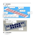
上中横梁规格: 180*45*6
边横梁规格: 180*45*6
竖梁规格: 120*50*6 下中横梁规格: 350*45*6
图六: 图六:货箱后板总成结构
上边梁:200*80*4
中横梁:200*60*4
中竖梁:230*70*4
边竖梁:200*80*4
下边梁: 异型 270 190) ( *80*4
7400 11*2 11
7600 11*2 11
7800 12*2 12
8000 12*2 12
8200 12*2 12
8500 12*2 12
图五: 图五:前板总成结构 1、中举升
帽沿规格: 2300*600
横梁规格: 100*50*4
竖梁规格: 100*40*4
2、前举升
帽沿规格: 2300*600*3
底板边横梁规格: 5800~6200:160*90*5-430(长度) 6500~7200:160*90*5-410(长度) 7400~8500:160*90*6-412(长度)
车型 参数 边横梁数 量 中横梁数 量
5800 9*2 9
6000 9*2 9
6200 9*2 9
6500 9*2 9
6800 10*2 10
20 22 21 20 26
21 27 23
方油箱
A
25 24 18
油泵 海沃:82/100 国产:100
2、7800~8200 、
竖筋宽:230*70*4 数量:7800/8000-6,8200-7 间距:7800-563,8000-603,8200-497
开口尺寸: 1236*469
图二: 图二:副车架总成结构
1、5400-5600 中顶
轻型载货汽车转向桥设计(机械CAD图纸)

轻型载货汽车转向桥设计摘要本设计为载重汽车的转向桥,此转向桥需要适应不同路况,不同速度下的稳定行驶,因此对前桥的要求也越来越高。
在汽车设计、制造、因此应该本着既能有足够的承载能力,又能实现耐用经济的思想进行方案的选择,为了降低生产成本,又在结构上满足要求的情况下应尽量简单。
通过设计:(1)保证有足够的强度:以保证可靠的承受车轮与车架之间的作用力。
(2)保证有足够的刚度:以使车轮定位参数不变。
(3)保证转向轮有正确的定位角度:以使转向轮运动稳定,操纵轻便并减轻轮胎的磨损。
(4)转向桥的质量应尽可能小:以减少非簧上质量,提高汽车行驶平顺性。
通过分析工作原理设计转向节、前轴、主销等零件的尺寸,使各个零部件的强度满足校核,并运用caxa等绘图软件绘制装配图和零件图。
关键词: 转向桥;定位参数;转向节;前轴;主销The design of the truck steering axleAbstractThis design is Steering Axle for heavy trucks. The design is need to adapt to different road and under different speeds, so the stability of front axle higher requirements. In car design, manufacture, and should be based on both have enough carrying capacity, and can achieve durable economic thoughts options, in order to reduce the production cost, and meets the requirements in the structure of situations should as far as possible simple.By design: (1) To ensure adequate strength: in order to ensure affordable and reliable force between wheel and frame. By design: (1) To ensure adequate strength: in order to ensure affordable and reliable force between wheel and frame. (2) Ensure adequate rigidity: in order to change the wheel alignment parameters. (3)To ensure the correct positioning of steering wheel angle: to make the steering wheel movement and stability, manipulating light and reduce tire wear. (4) The steering axle of quality should be as small as possible: to reduce the non-sprung mass, improve vehicle ride comfort.Works by analyzing the design of steering knuckle, front axle, kingpin and other parts of the size, so that the strength of the various components to meet the check, and use other mapping software caxa assembly drawing and parts are drawing.Key words: steering axle; positional parameters; knuckle; front axle;kingpin目录摘要............................................ 错误!未定义书签。
FCJ-型自行式液压翻车机设计(含全套CAD图纸)
摘 要翻车机是矿山常用的一种卸矿机械,原矿石由矿车编组运输至矿仓上方后, 由翻车机卸入矿仓,随着采矿技术的发展和提高产量的需要,原设计的翻车机往 往不能满足要求,FCJⅡ型的自行式液压翻车机是一种新型的翻车机,它很好的 解决了这一困难,生产实践表明,这种翻车机已成为重要的矿山生产设备。
FCJⅡ型的自行式液压翻车机是为满足矿山的需要,根据原研制的 FCJⅠ 型的压翻车机在使用中的情况,根据需要研改制而成的,更便于生产,提高了生 产效率,降低了工作强度。
此次设计是仿制设计,基本上采用李洪平教授研制的 液压翻车机样机的基本结构形式,结构和工作原理,通过对整机的结构了解,绘 制整机装配图,在此基础上自主研制翻车机的液压系统设计,主要包括系统工作 压力的确定,执行元件的控制确定,拟订液压系统原理图,计算执行元件主要参 数,选择液压控制元件和辅件,绘制管路布置图和设计液压站。
通过本次设计,研究和计算,成功的完成了 FCJⅡ型的自行式液压翻车机 上的液压系统设计。
关键词:液压翻车机,液压系统,原理,元件,参数。
AbstractThe tripping device is the mine commonly used one kind unloads the ore machinery, the raw ore by the mine car grouping transportation after the pocket above, unloads into the pocket by the tripping device, and enhances the output along with the mining technology development the need, the original design tripping device often cannot answer the purpose, the FCJ II like hydraulic pressure tripping device is one kind of new tripping device voluntarily, it very good solution this difficulty, the production practice had indicated, this kind of tripping device has become the important mine production equipment.The FCJ II like hydraulic pressure tripping device is voluntarily for satisfies the mine the need, according to the original development FCJ I pressure tripping device in use situation, according to needs to grind changes the system but becomes, is advantageous for the production, enhanced the production efficiency, reduced the working strength. This design imitates the design, basically uses the hydraulic pressure tripping device prototype basic structure form which Professor Li Hong even develops, the structure and the principle of work, through understood to the entire machine structure, draws up the entire machine assembly drawing, independently develops the tripping device in this foundation the hydraulic system design, mainly includes the system working pressure the determination, the functional element control determined, drafts the hydraulic system schematic diagram, the computation functional element main parameter, the choice hydraulic control part and auxiliary, draws up the piping plan and the design hydraulic pressure station.Through this design, the research and the computation, the success has completed on the FCJ II voluntarily like hydraulic pressure tripping device hydraulic system design.Student: Ouyang Wenliangthe Guide teacher: Li Hongping Key word: Hydraulic pressure tripping device, hydraulic system, principle, part,parameter.目 录第一章 引言1.1 研制的现状和意义 (1)1.2.题目介绍 (1)1.3 设计方案介绍 (2)1.4 现场条件主要参数 (4)第二章 翻车机的基本结构及工作原理2.1 整机机构 (5)2.2 行走机构 (5)2.3 工作机构 (6)2.4 液压系统 (7)2.5 电气系统 (7)第三章 .行走机构设计计算3.1 运行阻力计算 (8)3.2 电动机功率计算 (9)3.3 选电动机 (10)3.4 传动比的分配 (10)3.5 皮带传动设计 (10)3.6 链传动设计 (10)第四章 .工作机构的计算4.1 计算升举油缸受力 (11)4.2 计算夹持油缸受力 (11)4.3 计算翻转油缸受力 (12)4.4 链条选择 (12)4.5 花键强度验算 (13)第五章 液压系统设计计算5.1 工况分析 (14)5.2 初选系统压力 (14)5.3 油缸参数计算 (14)5.4 液压泵, 各缸的工作时间、 流量、 压力计算 (21)5.5 推车油缸 (30)5.6 计算液压泵的驱动功率 (31)5.7 液压缸结构的选用和计算 (31)5.8 液压系统原理图 (38)5.9 油箱设计 (39)5.10 辅件选择、计算 (41)5.11 液压元件的安装 (42)第六章 整机的稳定性计算 (43)致 谢 (44)参考文献 (45)第一章 引 言1.1研制的现状和意义翻车机是矿山常用的一种卸矿机械,原矿山由矿车编组运输至矿仓上方后, 由翻车机卸入矿仓。
毕业设计(论文)-轻型载货汽车(离合器及传动轴设计)(含全套cad图纸)[管理资料]
![毕业设计(论文)-轻型载货汽车(离合器及传动轴设计)(含全套cad图纸)[管理资料]](https://img.taocdn.com/s3/m/17c477db3169a4517623a38e.png)
目录前言 (1)第一章离合器的设计 (3)§ 绪论 (3)§ (3)§ (4)§ (6)§ (11)§ (12)§ (15)第二章离合器操作机构的设计 (19)§ (19)第三章传动轴的设计 (22)§ (22)§ (23)§ (24)结论 (27)参考文献 (28)致谢 (29)外文翻译 (30)前言改革开放以来,随着国家经济的迅猛发展,汽车工业也在慢慢崛起,汽车在我们日常生活中占据了越来越重要的地位,车辆给人们出行带来了极大地方便,因此汽车工业也被国家放在了极其重要的地位,像吉利收购沃尔沃表明了我们国内企业正在逐步强大,因此能够选择车辆工程专业也是我认为一个非常正确的选择,而汽车设计室我们车辆工程专业学生毕业时的一个重要实践环节。
这次设计中,我们五名同学共同合作,共同设计一辆轻型载货汽车,我主要负责其中的离合器和传动轴的设计。
在本次设计中,我选用的是目前比较广泛应用的液压操纵拉式膜片弹簧离合器。
这种离合器有许多优点,如操纵省力,布置方便,结构简单等。
传动轴采用的是十字轴式万向节,其与万向节叉的连接采用外挡圈式。
通过这次的设计,我们对大学四年所学的知识进行了一次全面的回顾与总结,并且进一步加深与巩固,同时也掌握了一些运用专业知识方法,提高了理论联系实际的能力,为今后工作和学习打下了良好的基础。
第一章离合器的设计§绪论汽车离合器的设计是汽车传动系中于发动机联系的总成。
离合器在汽车中的作用是:切断和实现对传动系的动力传递,以保证:,使汽车平稳起步,减少变速器中齿轮之间的冲击,便于换挡。
,靠离合器打滑保护传动系,防止零件因过载而损坏。
为保证离合器具有良好的工作性能,对汽车离合器提出如下基本的要求:A.在任何行驶情况下能可靠的传递发动机最大的转矩,而且传递扭矩的能力要有适当储备;B.分离是要彻底;,以保证汽车起步平稳,没有抖动和冲击;D离合器的从动部分转动惯量要小,以减轻换挡时齿轮之间的冲击和便于换挡;此外,离合器应力求做到结构简单、紧凑、重量轻,制造工艺性好和维修方便。
自卸车设计

普通自卸车的结构
普通自卸车的结构组成
1——液压倾卸操纵机构 4——拉臂 7——安全支架 10——备胎 13——副车架
2——三角臂 5——车箱 8——储油箱 11——挡泥板 14——防护栏
3——油缸 6——翻转轴支座 9——油泵 12——锁启机构
车箱的结构形式 车厢是用于装载和倾卸货物。它一般是由前板、左右边板、 后板和底板组成。
福田欧曼 欧曼系列车型使用独立总成供应商,靠着出色的匹配能力使 得产品的性能得到充分的发挥。 欧曼9系采用的是轮减桥,比较适合重载以及路况比较糟糕的 工况。欧曼9系采用13吨双级减速桥,装配260-480马力大扭 矩发动机,在斯太尔平台基础上,采用奔驰技术进行系统升 级,具有承载能力强的特点,适合重载和恶劣作业环境的使 用要求。 欧曼6系采用10-13吨单级减速桥,主配210-380马力康明斯动 力和康明斯技术的欧康动力,对整体进行轻量化设计,传动 效率高,比较适合公路高速标载运输的要求。
油缸浮动式举升机构直推式与连杆组合式举升机构的综合比较类别项目连杆组合式结构布置简便易于布置比较复杂油缸加工工艺多级缸加工精度高工艺性差单级缸制造简便工艺系统密封性密封环节多易渗漏密封性差密封环节少不易渗漏密封性好工作寿命磨损大易损坏工作寿命较短不易损坏工作寿命较长制造成本较高较低系统倾卸稳定性较差较好自卸车的几个重要参数1自卸汽车的质量利用系数自卸汽车的质量利用系数go是指装载质量m之比即go该系数是一项评价汽车设计制造水平的综合性指标
另一类用于公路运输用的轻、中、重型(装载质量在2~20 t) 普通自卸汽车。它主要承担砂石、泥土、煤炭等松散货物运 输,通常是与装载机配套使用。 普通自卸汽车技装载质量 分为:轻型自卸汽车 、中型自 卸汽车 和重型自卸汽车 ;按运载货物倾卸方向分为:后倾式 、侧倾式、三开、五开倾式和底板倾卸卸式自卸汽车;按车 厢栏板结构分为:栏板一面开启式、栏板三面开启式和簸箕 式(即无后栏板)自卸汽车。 随着国内基础设施建设需要不断增加,自卸车产量近年 来一直保持较高产销量,在专用车综合产量中保持第一位置 ,但在种类、型式、材料运用方面与国外还有一定的差距。 自卸汽车继续快速增长,销量超过载货汽车上升到第一位。 主要原因是固定资产投资强劲增长,巨大的投资规模奠定了 自卸车市场需求基础;自卸汽车品种增加,不仅适应和满足 施工需求,同时向运输市场发展;牵引汽车保持较快发展, 已成为长距离公路运输的主力车型。
CA1040轻型货车驱动桥设计(全套图纸)

摘要驱动桥位于传动系末端,其基本功用是增矩、降速,承受作用于路面和车架或车身之间的作用力。
它的性能好坏直接影响整车性能,而对于载重汽车显得尤为重要。
轻型货车在商用货运汽车生产中占有很大的比重,为满足目前当前载货汽车的高速度、高效率、高效益的需要,必须要搭配一个高效、可靠的驱动桥。
因此设计出结构简单、工作可靠、造价低廉的驱动桥,能大大降低整车生产的总成本,推动汽车经济的发展,并且通过对汽车驱动桥的学习和设计实践,可以更好的学习并掌握现代汽车设计与机械设计的全面知识和技能,所以本课题设计一款结构优良的轻型货车驱动桥具有一定的实际意义。
驱动桥设计应主要保证汽车在给定的条件下具有最佳的动力性和燃油经济性。
本设计根据给定的参数,按照传统设计方法并参考同类型车确定汽车总体参数,再确定主减速器、差速器、半轴和桥壳的结构类型,最后进行参数设计并对主减速器主、从动齿轮、半轴齿轮和行星齿轮进行强度以及寿命的校核。
驱动桥设计过程中基本保证结构合理,符合实际应用,总成及零部件的设计能尽量满足零件的标准化、部件的通用化和产品的系列化及汽车变型的要求,修理、保养方便,机件工艺性好,制造容易。
关键词:驱动桥;单级主减速器;差速器;半轴;桥壳ABSTRACTDrive axle is at the end of the power train, and its basic function is increasing the torque and reducing the speed, bearing the force between the road and the frame or body. Its performance will have a direct impact on automobile performance .Because using the big power engine with the big driving torque satisfied the need of high speed,heavy-loaded,high efficiency,high benefit today’ heavy truck,must exploiting the high driven efficiency single reduction final drive axle is becoming the heavy truck’ developing tendency. Because using the big power engine with the big driving torque satisfied the need of high speed, heavy-loaded, high efficiency, high benefit today` truck, must exploiting the high driven efficiency single reduction fin al drive axle is becoming the trucks’ developing tendency. Design a simple, reliable, low cost of the drive axle, can greatly reduce the total cost of vehicle production, and promote the economic development of automobile and automotive drive axle of the study and design practice, can better learn and to master modern automotive design and mechanical design of a comprehensive knowledge and skills, so the title of the fine structure of the design of a pickup vehicle drive axle has a certain practical significance.According to the design parameters given ,firstly determine the overall vehicle parameters in accordance with the traditional design methods and reference the same vehicle parameters, then identify the main reducer, differential, axle and axle housing structure type, finally design the parameters of the main gear, the driven gear of the final drive, axle gears and spiral bevel gear and check the strength and life of them. In design process of the drive axle, we should ensure a reasonable structure, practical applications, the design of assembly and parts as much as possible meeting requirements of the standardization of parts, components and products’ universality and the serialization and change , convenience of repair and maintenance, good mechanical technology, being easy to manufacture.Key words: Drive axle; Single reduction final drive; Differential; Axle; Drive Axle housing目录摘要 (Ⅰ)Abstract (Ⅱ)第1章绪论 (1)1.1 论文研究的背景及意义 (1)1.2 国内外研究现状 (2)1.2.1 国外研究现状 (2)1.2.2 国内研究现状 (3)1.3 设计的主要内容 (4)第2章驱动桥总体方案设计 (5)2.1 汽车车桥的种类 (5)2.2 驱动桥的种类 (5)2.2.1 非断开式驱动桥 (5)2.2.2 断开式驱动桥 (6)2.3 多驱动桥的布置 (6)2.4 驱动桥的设计要求 (7)2.5 设计车型参数 (7)2.6 主减速器方案 (8)i的确定 (8)2.6.1 主传动比2.6.2 主减速器的齿轮类型 (9)2.6.3 主减速器的减速形式 (10)2.6.4 主减速器主从动锥齿轮的支撑方案 (11)2.7 差速器结构方案的确定 (12)2.8 半轴形式的确定 (13)2.9 桥壳形式的确定 (14)2.10 本章小结 (15)第3章主减速器设计 (16)3.1 概述 (16)3.2 主减速器齿轮参数的选择及强度计算 (16)3.2.1 主减速器齿轮计算载荷的确定 (16)3.2.2 锥齿轮主要参数的选择 (17)3.2.3 主减速器齿轮材料的选择 (21)3.2.4 主减速器齿轮强度的计算 (21)3.3 主减速器轴承的选择 (25)3.4 主减速器的润滑 (30)3.5 本章小结 (30)第4章差速器设计 (31)4.1概述 (31)4.2 对称式行星齿轮差速器工作原理 (31)4.3 对称式行星齿轮差速器的结构 (32)4.4 对称式行星圆锥齿轮设计 (32)4.4.1 差速器齿轮的材料 (32)4.4.2 差速器齿轮的基本参数选择 (33)4.4.3 差速器齿轮几何尺寸计算 (35)4.4.4 差速器齿轮强度计算 (36)4.5 本章小结 (38)第5章半轴设计 (39)5.1 概述 (39)5.2 半轴的设计 (39)5.2.1半轴材料与热处理 (39)5.2.2全浮式半轴的计算载荷的确定 (39)5.2.3全浮半轴杆部直径的初选 (41)5.2.4全浮半轴强度计算 (41)5.2.5全浮式半轴花键强度计算 (42)5.3 本章小结 (43)第6章驱动桥桥壳的设计 (44)6.1 概述 (44)6.2桥壳的受力分析及强度计算 (44)6.2.1桥壳的静弯曲应力计算 (44)6.2.2在不平路面冲击载荷作用下桥壳的强度计算 (46)6.2.3汽车以最大牵引力行驶时的桥壳的强度计算 (46)6.2.4汽车紧急制动时的桥壳强度计算 (48)6.2.5 汽车受最大侧向力时桥壳的强度计算 (50)6.3 本章小结 (53)结论 (55)参考文献 (56)致谢 (58)第1章绪论1.1 论文研究的背景及意义近年来,我国汽车行业迅猛发展,2009年我国汽车产销分别完1379.10万辆和1364.48万辆,同比分别增长48%和46%。
NTQ3040B轻型农用自卸车车厢和举升机构毕业设计

目录摘要 ..................................................................................................................................... Abstract. (Ⅱ)第1章绪论 (3)1.1 课题的提出 (3)1.2 专用汽车设计特点 (5)1.3课题的实际意义 (6)1.4 国内外自卸汽车的发展概况 (7)第2章轻型自卸车主要性能参数的选择 (10)2.1整车尺寸参数的确定 (10)2.2质量参数的确定 (10)2.3其它性能参数 (12)2.4本章小结 (13)第3章自卸车车厢的结构与设计 (14)3.1自卸汽车车厢的结构形式 (14)3.1.1车厢的结构形式 (14)3.1.2车厢选材 (15)3.2车厢的设计规范及尺寸确定 (15)3.2.1车厢尺寸设计 (15)3.2.2车厢内框尺寸及车厢质量 (16)3.3车厢板的锁启机构 (17)3.4本章小结 (17)第4章自卸举升机构的设计 (18)4.1自卸举升机构的选择 (18)4.1.1举升机构的类型 (18)4.1.2自卸汽车倾卸机构性能比较 (21)4.2举升机构运动与受力分析及参数选择 (23)4.2.1机构运动分析 (25)4.2.2举升机构受力分析与参数选择 (26)4.3本章小结 (26)第5章液压系统设计 (27)5.1液压系统工作原理与结构特点 (27)5.1.1工作原理 (27)5.1.2液压系统结构布置 (28)5.1.3液压分配阀 (28)5.2油缸选型与计算 (29)5.3油箱容积与油管内径计算 (30)5.4取力器的设计 (31)5.5本章小结 (35)第6章副车架的设计 (36)6.1副车架的截面形状及尺寸 (36)6.2副车架前段形状及位置 (36)6.2.1副车架的前端形状及安装位置 (36)6.2.2 纵梁与横梁的连接设计 (38)6.2.3 副车架与主车架的连接设计 (36)6.3副车架主要尺寸参数设计计算 (37)6.3.1副车架主要尺寸设计 (37)6.3.2副车架的强度刚度弯曲适应性校核 (37)6.4本章小结 (44)结论 (45)参考文献 (46)致谢 (47)绪论1.1 课题的提出专用自卸车是装有液压举升机构,能将车厢卸下或使车厢倾斜一定角度,货物依靠自重能自行卸下或者水平推挤卸料的专用汽车。
CA1040轻型货车驱动桥设计(全套图纸)
摘要驱动桥位于传动系末端,其基本功用是增矩、降速,承受作用于路面和车架或车身之间的作用力。
它的性能好坏直接影响整车性能,而对于载重汽车显得尤为重要。
轻型货车在商用货运汽车生产中占有很大的比重,为满足目前当前载货汽车的高速度、高效率、高效益的需要,必须要搭配一个高效、可靠的驱动桥。
因此设计出结构简单、工作可靠、造价低廉的驱动桥,能大大降低整车生产的总成本,推动汽车经济的发展,并且通过对汽车驱动桥的学习和设计实践,可以更好的学习并掌握现代汽车设计与机械设计的全面知识和技能,所以本课题设计一款结构优良的轻型货车驱动桥具有一定的实际意义。
驱动桥设计应主要保证汽车在给定的条件下具有最佳的动力性和燃油经济性。
本设计根据给定的参数,按照传统设计方法并参考同类型车确定汽车总体参数,再确定主减速器、差速器、半轴和桥壳的结构类型,最后进行参数设计并对主减速器主、从动齿轮、半轴齿轮和行星齿轮进行强度以及寿命的校核。
驱动桥设计过程中基本保证结构合理,符合实际应用,总成及零部件的设计能尽量满足零件的标准化、部件的通用化和产品的系列化及汽车变型的要求,修理、保养方便,机件工艺性好,制造容易。
关键词:驱动桥;单级主减速器;差速器;半轴;桥壳ABSTRACTDrive axle is at the end of the power train, and its basic function is increasing the torque and reducing the speed, bearing the force between the road and the frame or body. Its performance will have a direct impact on automobile performance .Because using the big power engine with the big driving torque satisfied the need of high speed,heavy-loaded,high efficiency,high benefit today’ heavy truck,must exploiting the high driven efficiency single reduction final drive axle is becoming the heavy truck’ developing tendency. Because using the big power engine with the big driving torque satisfied the need of high speed, heavy-loaded, high efficiency, high benefit today` truck, must exploiting the high driven efficiency single reduction fin al drive axle is becoming the trucks’ developing tendency. Design a simple, reliable, low cost of the drive axle, can greatly reduce the total cost of vehicle production, and promote the economic development of automobile and automotive drive axle of the study and design practice, can better learn and to master modern automotive design and mechanical design of a comprehensive knowledge and skills, so the title of the fine structure of the design of a pickup vehicle drive axle has a certain practical significance.According to the design parameters given ,firstly determine the overall vehicle parameters in accordance with the traditional design methods and reference the same vehicle parameters, then identify the main reducer, differential, axle and axle housing structure type, finally design the parameters of the main gear, the driven gear of the final drive, axle gears and spiral bevel gear and check the strength and life of them. In design process of the drive axle, we should ensure a reasonable structure, practical applications, the design of assembly and parts as much as possible meeting requirements of the standardization of parts, components and products’ universality and the serialization and change , convenience of repair and maintenance, good mechanical technology, being easy to manufacture.Key words: Drive axle; Single reduction final drive; Differential; Axle; Drive Axle housing目录摘要 (Ⅰ)Abstract (Ⅱ)第1章绪论 (1)1.1 论文研究的背景及意义 (1)1.2 国内外研究现状 (2)1.2.1 国外研究现状 (2)1.2.2 国内研究现状 (3)1.3 设计的主要内容 (4)第2章驱动桥总体方案设计 (5)2.1 汽车车桥的种类 (5)2.2 驱动桥的种类 (5)2.2.1 非断开式驱动桥 (5)2.2.2 断开式驱动桥 (6)2.3 多驱动桥的布置 (6)2.4 驱动桥的设计要求 (7)2.5 设计车型参数 (7)2.6 主减速器方案 (8)i的确定 (8)2.6.1 主传动比2.6.2 主减速器的齿轮类型 (9)2.6.3 主减速器的减速形式 (10)2.6.4 主减速器主从动锥齿轮的支撑方案 (11)2.7 差速器结构方案的确定 (12)2.8 半轴形式的确定 (13)2.9 桥壳形式的确定 (14)2.10 本章小结 (15)第3章主减速器设计 (16)3.1 概述 (16)3.2 主减速器齿轮参数的选择及强度计算 (16)3.2.1 主减速器齿轮计算载荷的确定 (16)3.2.2 锥齿轮主要参数的选择 (17)3.2.3 主减速器齿轮材料的选择 (21)3.2.4 主减速器齿轮强度的计算 (21)3.3 主减速器轴承的选择 (25)3.4 主减速器的润滑 (30)3.5 本章小结 (30)第4章差速器设计 (31)4.1概述 (31)4.2 对称式行星齿轮差速器工作原理 (31)4.3 对称式行星齿轮差速器的结构 (32)4.4 对称式行星圆锥齿轮设计 (32)4.4.1 差速器齿轮的材料 (32)4.4.2 差速器齿轮的基本参数选择 (33)4.4.3 差速器齿轮几何尺寸计算 (35)4.4.4 差速器齿轮强度计算 (36)4.5 本章小结 (38)第5章半轴设计 (39)5.1 概述 (39)5.2 半轴的设计 (39)5.2.1半轴材料与热处理 (39)5.2.2全浮式半轴的计算载荷的确定 (39)5.2.3全浮半轴杆部直径的初选 (41)5.2.4全浮半轴强度计算 (41)5.2.5全浮式半轴花键强度计算 (42)5.3 本章小结 (43)第6章驱动桥桥壳的设计 (44)6.1 概述 (44)6.2桥壳的受力分析及强度计算 (44)6.2.1桥壳的静弯曲应力计算 (44)6.2.2在不平路面冲击载荷作用下桥壳的强度计算 (46)6.2.3汽车以最大牵引力行驶时的桥壳的强度计算 (46)6.2.4汽车紧急制动时的桥壳强度计算 (48)6.2.5 汽车受最大侧向力时桥壳的强度计算 (50)6.3 本章小结 (53)结论 (55)参考文献 (56)致谢 (58)第1章绪论1.1 论文研究的背景及意义近年来,我国汽车行业迅猛发展,2009年我国汽车产销分别完1379.10万辆和1364.48万辆,同比分别增长48%和46%。