HONEYWELL DC1000系列温控器手册
Honeywell说明书,通讯00B版doc

32
DC1030 系列接线图
Honeywell
您值得信赖的合做伙伴
33
DC1040 系列接线图
Honeywell
您值得信赖的合做伙伴
34
Honeywell
您值得信赖的合做伙伴
35
Honeywell
您值得信赖的合做伙伴
9
操作说明
Honeywell
您值得信赖的合做伙伴
10
5.
输入
Honeywell
您值得信赖的合做伙伴
11
若客户没有指定输入类型,出厂值预设为 “K2” 其他任意电压电流范围,请来电咨询。
Honeywell
您值得信赖的合做伙伴
12
6.
警报作用
备注: Hold-ON 代表的意思是第一次不报警 .
26
Honeywell
您值得信赖的合做伙伴
27
Honeywell
您值得信赖的合做伙伴
28
Honeywell
您值得信赖的合做伙伴
29
Honeywell
您值得信赖的合做伙伴
30
DC1010 系列接线图
Honeywell
您值得信赖的合做伙伴
31
DC1020 系列接线图
Honeywell
您值得信赖的合做伙伴
Honeywell
您值得信赖的合做伙伴
8
◆ 当SET8.3=1(程序运行时,从“PV”开 始 ) , 即 PV热启动,程序自动扣除运行段的时 间,剩余时间会显示在参数“TIMER”上 ◆ 请非专业人员勿修改“LEVEL 4”层参数, ,否则可能造成控制器内部错误。
4.5
PROGRAM
(用于可编程控制器) LEVEL LEVEL(
10301040系列HONEYWELL温控表,HONEYWELL智能调

10301040系列HONEYWELL温控表,HONEYWELL智能调一.霍尼韦尔DC1000系列操纵器(DC1010,DC1020,DC1030,DC1040)是针对大型OEM用户而设计的可选功能相对简单、价格低廉的新型操纵器。
在相同档次的同类产品中,具有功能全、质量好、性价比高的优势,是国内设备制造商、电气成套商等规模用户的理想产品,同时也产品描述面板尺寸:48x48mm(DC1010)、48x96mm(DC1020)、72x72mm(DC1030)、96x96mm(DC1040)、模拟输入:1-2个输入类型:热电偶、RTD、mV、mA模拟输出:2路传送输出:1路数字输出操纵:最多2个数字输出报警:2-3个精度:+/-0.5%量程操纵回路:1个通讯:RS232/RS485双排显示PV、SP等数据12种热电偶信号、3种热电阻信号、5种线形信号输入继电器输出、电压、电流信号输出带手/自动模式,切换便利多种辅助输出功能多种操纵算法输出:ON/OFF、PID、双重〔冷热区〕输出、马达阀门操纵,单相/三相可控硅操纵三路〔可选〕报警输出,17种报警类型2套各8段设定点程序,切换调用或串接成16段程序使用满量程0.5%精度,EEROM非易失性内存,确保数据在掉电情况下可不能丢失85-256Vac/50〔60〕HZ供电工作DC1010,DC1020,DC1030,DC1040霍尼韦尔DC1000系列数字操纵器,是针对大型OEM用户而设计的可选功能相对简单、价格低廉的新型操纵器。
在相同档次的同类产品中,具有功能全、质量好、性价比高的优势,是国内设备制造商、电气成套商等规模用户的理想产品,同时也是各种温度操纵及其它变量操纵的最正确选择。
二.图片三、具体型号DC1040CT-101-000-EDC1040CT-201-000-EDC1040CT-301-000-EDC1040CT-701-000-EDC1040CT-101-00B-E DC1040CT-201-00B-EDC1040CT-301-00B-EDC1040CT-102-000-EDC1040CT-202-000-EDC1040CT-302-000-EDC1040CT-702-000-EDC1040CR-101-000-EDC1040CR-201-000-EDC1040CR-301-000-EDC1040CR-701-000-EDC1040CR-101-00B-E DC1040CR-201-00B-EDC1040CR-301-00B-EDC1040CR-102-000-E DC1040CR-202-000-EDC1040CR-302-000-EDC1040CR-702-000-EDC1040CL-101-000-EDC1040CL-201-000-EDC1040CL-301-000-EDC1040CL-701-000-EDC1040CL-101-002-E DC1040CL-201-002-EDC1040CL-301-002-EDC1040CL-102-000-E DC1040CL-202-000-EDC1040CL-302-000-EDC1040CL-702-000-EDC1020CT-201-000-EDC1020CT-301-000-EDC1020CT-701-000-EDC1020CT-202-000-E DC1020CT-302-000-EDC1020CT-702-000-EDC1020CR-101-000-EDC1020CR-201-000-EDC1020CR-301-000-EDC1020CR-701-000-EDC1020CR-102-000-E DC1020CR-202-000-EDC1020CR-302-000-EDC1020CR-702-000-EDC1020CL-101-000-EDC1020CL-201-000-EDC1020CL-301-000-EDC1020CL-701-000-EDC1020CL-102-000-E DC1020CL-202-000-EDC1020CL-302-000-EDC1020CL-702-000-EDC1030CT-101-000-E DC1030CT-201-000-E DC1030CT-301-000-E DC1030CT-701-000-E DC1030CR-101-000-E DC1030CR-201-000-E DC1030CR-301-000-E DC1030CR-701-000-E DC1030CL-101-000-E DC1030CL-201-000-E DC1030CL-301-000-E DC1030CL-701-000-E DC1010CT-101-000-E DC1010CT-201-000-E DC1010CT-301-000-E DC1010CT-701-000-E DC1010CR-101-000-E DC1010CR-201-000-E DC1010CR-301-000-E DC1010CR-701-000-E DC1010CL-101-000-E DC1010CL-201-000-E DC1010CL-301-000-E DC1010CL-701-000-E。
霍尼韦尔说明书
霍尼韦尔说明书霍尼韦尔说明书简介霍尼韦尔(Honeywell)是一家全球领先的多元化科技和制造公司,总部位于美国,成立于1906年。
公司的业务涵盖航空航天、楼宇技术、性能材料、可持续性解决方案和安全解决方案等领域。
霍尼韦尔以其创新的技术、高品质的产品和可靠的性能享誉全球。
本文档旨在向用户提供关于霍尼韦尔产品的说明,并介绍如何正确使用和维护这些产品。
产品列表1. 霍尼韦尔智能温控器* 产品名称:霍尼韦尔智能温控器* 产品型号:TH9320WF5003* 产品特点:- 可与智能手机和智能家居系统连接,实现远程控制- 可编程设置温度和计划,提高能源效率- 大屏幕显示温度和湿度等信息* 使用说明:1. 将温控器与电源连接,并按照说明书设置温度和计划。
2. 下载并安装霍尼韦尔智能手机应用。
3. 打开应用,按照提示添加温控器设备。
4. 连接温控器和手机,即可实现远程控制。
2. 霍尼韦尔空气净化器* 产品名称:霍尼韦尔空气净化器* 产品型号:HFD-120-Q* 产品特点:- 高效过滤空气中的颗粒物和有害物质- 自动检测空气质量,并自动调整清洁模式- 低噪音设计,不影响正常生活* 使用说明:1. 将空气净化器放置在需要净化的房间内,并连接电源。
2. 按下电源开关,启动空气净化器。
3. 空气净化器将自动检测空气质量,并根据需要调整清洁模式。
4. 定期更换空气净化器中的滤网,以确保最佳的净化效果。
常见问题与解答Q1:为什么温控器无法连接智能手机?A:请确保智能手机和温控器处于相同的Wi-Fi网络下,并且已经下载并安装了霍尼韦尔智能手机应用。
如果问题仍然存在,请尝试重新连接温控器。
Q2:空气净化器何时需要更换滤网?A:根据使用环境和空气质量,滤网的寿命可能会有所不同。
一般建议每3至6个月更换一次滤网,或者根据空气净化器上的指示灯提示更换。
维护与保养为了保证霍尼韦尔产品的正常运行和延长使用寿命,以下是一些维护与保养的建议:1. 定期检查产品的电源和连接线,确保其无损坏和松动。
DC1000系列数字控制器产品说明说明书
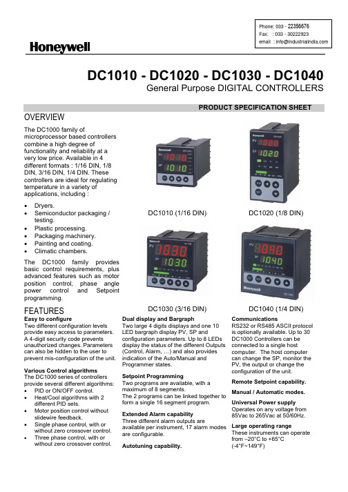
DC1010 - DC1020 - DC1030 - DC1040General Purpose DIGITAL CONTROLLERSPRODUCT SPECIFICATION SHEETDC1010 (1/16 DIN) DC1020 (1/8 DIN)OVERVIEWThe DC1000 family ofmicroprocessor based controllers combine a high degree offunctionality and reliability at a very low price. Available in 4 different formats : 1/16 DIN, 1/8 DIN, 3/16 DIN, 1/4 DIN. These controllers are ideal for regulating temperature in a variety of applications, including : x Dryers.x Semiconductor packaging /testing.x Plastic processing.x Packaging machinery.x Painting and coating.x Climatic chambers.The DC1000 family provides basic control requirements, plus advanced features such as motor position control, phase angle power control and Setpoint programming.FEATURESDC1030 (3/16 DIN)DC1040 (1/4 DIN)Easy to configureTwo different configuration levels provide easy access to parameters. A 4-digit security code prevents unauthorized changes. Parameters can also be hidden to the user to prevent mis-configuration of the unit. Various Control algorithms The DC1000 series of controllers provide several different algorithms: x PID or ON/OFF control.x Heat/Cool algorithms with 2different PID sets.x Motor position control withoutslidewire feedback.x Single phase control, with orwithout zero crossover control. x Three phase control, with orwithout zero crossover control.Dual display and BargraphTwo large 4 digits displays and one 10 LED bargraph display PV, SP andconfiguration parameters. Up to 8 LEDs display the status of the different Outputs (Control, Alarm, …) and also provides indication of the Auto/Manual and Programmer states.Setpoint ProgrammingTwo programs are available, with amaximum of 8 segments. The 2 programs can be linked together to form a single 16 segment program.Extended Alarm capability Three different alarm outputs areavailable per instrument, 17 alarm modes are configurable.CommunicationsRS232 or RS485 ASCII protocol is optionally available. Up to 30 DC1000 Controllers can be connected to a single host computer. The host computer can change the SP, monitor the PV, the output or change the configuration of the unit.Remote Setpoint capability. Manual / Automatic modes. Universal Power supplyOperates on any voltage from85Vac to 265Vac at 50/60Hz. Large operating rangeThese instruments can operate from –20°C to +65°CSPECIFICATIONSThermocouples : K, J, R, S, B, E, N, T, W, PL II, U, L Type of InputRTD : Pt100, JPt100, JPt50PV InputLinear : 4~20mAInput Sampling Time 500 msInput Resolution 14 bit (each)PV/SP Indication 4-digit, 7 segment displayIndicationConstant Value Storage System Non-volatile memory (E2PROM)Indication Accuracy 0.5%FSProportional Band ( P ) 0~200% (On/Off action at P=0)Integral Time ( I ) 0~3600 sec (PD action at I=0)Control ModeDerivative Time ( D ) 0~900 sec (PI action at D=0)Cycle Time 0~150 sec (4~20mA=0, SSR=1, Relay=10)Dead Band Time 0~1000 sec (dead time compensation)Relay Output Electromechanical relayx SPDT contactsx 3A/240VacStatic relay driver output Voltage Pulse, 20VDC/20mAOutputCurrent & Voltage outputs 0~20mA, 4~20mA,0~5V, 0~10V, 1~5V, 2~10VMotor Control Output Servo motor valve control (open loop circuit)Others Phase angle control :9 1M SSR, 3M SSR, 1M SCR, 3M SCRNumber Up to 3 (optional)Modes 17 alarm modes available, hability to ignore the alarmthe first time it occurs :9 Deviation high or low alarms.9 Deviation alarms.9 Band alarm.Alarm9 High or low alarm.9 End of segment alarm.9 Program run indication alarm.9 Timer alarm.Timer One timer is associated with each alarm.Output Signal SP, PVRetransmissionoutput Type of Output 4~20mA, 0~20mA, 0~5V, 0~10V, 1~5V, 2~10VType of Input4~20mA, 0~20mA, 0~5V, 0~10V, 1~5V, 2~10V 2nd Input (Remote SP) Sampling Time 500 ms.Programs Number2 programs of 8 segments each. CommunicationType of CommunicationRS-232 or RS-485. ASCII protocol.Rated Power Supply Voltage & FrequencyAC 85 ~ 265V, 50/60Hz Power Consumption 8VA (110V), 12VA (220V) Ambient Temperature -20°C ~ 65°C (-4°F ~ 149°F) Operating conditionsAmbient Humidity50 ~ 85% RH (non condensing) ApprovalsUL Pending. CE Mark.x PID or ON/OFF control.x Heat/Cool algorithms with 2 different PID sets.x Phase angle controlSingle PhaseThree Phase3I LOADIn phase angle control, power is regulated by changing the point at which the SCR is turned on within each 1/2 period. Single Phase : Output is changed every half-cycle in response to output signals from the Temperature Controller. Three Phase : The outputs are changed every 120° in response to signals from the Temperature Controller. Using this form of control, high-precision temperature control is possible.x Zero-crossover controlSingle Phase1I LOADThree Phase3I LOADThe term Zero-Crossover means that the SCR's are turned on only when the instantaneous value of the sinusoidal wave is zero. Power is then applied for a several continuous half-cycles and then removed for several half-cycles to achieve the desired load power.x Motor position control without slidewire Feedback.MOTOR VALVEMotor position is achieved by using time proportional controlwithout the need for slidewire feedback from the motor shaft. Slidewires wear over a period of time, which can result in poor or intermittent control. This type of control reduces maintenance requirements and removes the need for the controller to be calibrated to the motor feed back potentiometer.DC101050 mm - 1.97 in74.5 mm - 2.97 in13.5 mm 0.53 in6 mm 0.24 in 44 m m - 1.73 i n50 m m - 1.97 i n68 mm - 2.68 in60 m m - 2.36 i n45.5 mm - 1.79 in 45.5 m m - 1.79 i nDC102074.5 mm - 2.97 in13.5 mm 0.53 in6 mm 0.24 in86 mm 3.39 in96 m m - 3.78 i n48 mm - 1.89 in60 mm - 2.36 in91mm 3.58 in45.5mm 1.79 in116 mm 4.57 inDC103074.5 mm - 2.97 in13.5 mm 0.53 in6 mm 0.24 in66 m m - 2.60 i n72 mm - 2.83 in72 m m - 2.83 i n91 mm - 3.58 in69.55 mm 2.74 in91 m m - 3.58 i n69.55 mm 2.74 inContact Details:Industrial Supply Syndicate54, Ezra Street, Kolkata - 700 001, INDIAPhone: 22350923, 22356676 Fax: 91-33-30222923。
DC1000说明书

安全预防……………………………………………………………………………
8
选择合适的位置…………………………………………………………………
8
叠放………………………………………………………………………………… 8
输入接线…………………………………………………………………………… 8
输出连接………………………………………………………………………………… 9
气瓶有爆炸的危险性 7.a.只能使用含有正确焊接保护气体的压缩气 体气瓶,并正确操作气体和压力调节器。所有 胶管和配件等等必须符合应用且状况良好。 7.b.使用角架或固定支座固定气瓶并保持气瓶 直立。 7.c.气瓶应位于: • 远离能够被打击或有形损坏的地方。 • 与焊接或切割操作和气体热源,火源,飞
溅等保持安全距离。 7.d.禁止用焊条,焊钳或其它带电物体接触气 瓶。 7.e.当打开气瓶阀门时操作者的头及脸应避免 正对阀门出口。 7.f.阀门保护应在正确位置并用手拧紧,除非 气瓶将要或正在使用。 7.g.从压缩气体组织 1235 Jefferson Daves Highway, Arlington, VA22202 处得到 CGA 发 行 P-1”正确处理气瓶中的压缩气体的安全防范
谨防焊接烟尘 5.a.焊接产生的废气等不利于身体健康。应避免吸入 这些废气。当焊接时,头部不要面对这些废气。使 用足够的通风设备以使废气远离呼吸区。在使用焊 条焊接不锈钢或覆硬层(参照有关容器或 MSDS 的条 款)或含铅或镀镉钢或其它材料或覆有其它能够产生 有毒烟雾的涂层等需要特殊通风设备材料时,尽量 减少暴露并且当低于最低限值(TLV)时使用局部排 气或机械通风设备。在限定区域或户外,需要防护 面罩。焊接镀锌钢时也需注意。 5.b.禁止在因润滑,清洁或喷雾操作而来的氯化碳氢 化合物蒸汽附近焊接。电弧热和弧光与其反应生成 有剧毒的气体碳酰氯和气体刺激物。 5.c.用于焊接的保护气体会对身体造成伤害甚至死 亡。需使用足够的通风设备,尤其在狭窄的工作 区,更应保证呼吸的安全。 5.d.阅读并理解厂家说明书中的设备,消耗品,包括 材料安全数据库(MSDS)并遵照雇主的安全经验。请 从分销商或厂家处获得 MSDS。 5.e.参照第 1.B 款。
霍尼韦尔温控器DC10选型资料
1DC1010/1020/1030/1040 产品手册1DC1000系列通用控制器中文操作手册½öÓÃÓÚÆÀ¹À¡£°æȨËùÓÐ (c) by Foxit Software Company, 2004ÓÉ Foxit PDF Editor ±à¼-2DC1010/1020/1030/1040 PRODUCT MANUAL3DC1010/1020/1030/1040 产品手册34DC1010/1020/1030/1040 PRODUCT MANUAL5DC1010/1020/1030/1040 产品手册 5LCK=0001, 只进入LEVEL1并允许改变SP 值 LCK=0101, 除改变LCK 功能外,其它任何参数不能改变7DC1010/1020/1030/1040 产品手册79DC1010/1020/1030/1040 产品手册9假设SET8.3=1,SP值西安市将被改成PV值显示。
达到期望SP值的时间将被减少。
达到SP值的剩余时间显示在参数‘TMER’中。
在此,倒计数的时间是与PV值相关,而不是程序段。
11DC1010/1020/1030/1040 产品手册1112DC1010/1020/1030/1040 PRODUCT MANUAL13DC1010/1020/1030/1040 产品手册133) 结束功能如果ALD 设定为 17 (* 参看选择表), 此程序将在程序8或程序段16结束。
* 这样,在显示窗口中的 PV 和 END 将闪烁,报警继电器动作。
如果程序少于八个程序段,控制器就没有END 命令。
这样,请将下一程序段的 OUT 设定为0(out=0),程序就将在下一设定程序段结束。
工业测量与控制DC1000系列数字控制器产品手册说明书

Copyright, Notices, and TrademarksPrinted in Taiwan - © Copyright 2004 Honeywell International Inc.Issue 1 - March 2004Warranty / RemedyHoneywell warrants goods of its manufacture as being free to defective materials and faulty workmanship. Contact your local sales office for warranty information. If warranted goods are returned to Honeywell during the period of coverage, Honeywell will repair or replace without charge those items it finds defective. The foregoing is Buyer’s sole remedy and is in lieu of all other warranties, expressed or implied, including those of merchantability and fitness for a particular purpose. Specifications may change without notice. The information we supply is believed to be accurate and reliable as of this printing. However, we assume no responsibility for its use.While we provide application assistance personally, through our literature and the Honeywell web site, it is up to the customer to determine the suitability of the product in the application.© Copyright 2004 Honeywell International Inc.Sales and ServiceHoneywell serves its customers through a worldwide network of sales offices and distributors. For application assistance, current specifications, pricing, or name of the nearest Authorized Distributor, contact your local sales office. See back pageIndustrial Measurement and ControlHoneywell Korea191 HanGangRo 2ga, YongSanGuSeoul, KoreaContents1.Overview (1)1.1Introduction (1)2.Installation (2)2.1Model Number Interpretation (2)2.2Specification (3)2.3Mounting (4)2.4External Dimension (4)2.4.1DC1010 (4)2.4.2DC1020 (5)2.4.3DC1030 (5)2.4.4DC1040 (5)2.5Wiring Diagrams (6)2.5.1DC1010 (7)2.5.2DC1020 (8)2.5.3DC1030 (9)2.5.4DC1040 (10)3.Configuration (11)3.1Operator Interface (11)3.2MODE Access (12)3.3MODEs (13)3.3.1Operation (13)3.3.2Configuration 1 (14)3.3.3Configuration 2 (15)3.4Alarms (17)3.4.1Deviation Alarm (17)3.4.2Absolute Value Alarm (18)3.4.3Program Alarm (19)3.4.4System Alarm (19)3.5Function Lock (20)4.Input Codes (21)4.1Thermocouples (21)4.2RTDs (22)4.3Linear Inputs (22)5.Operation (23)5.1Type of Control (23)5.1.1Manual Operation (23)5.1.2ON/OFF Control (23)5.1.3PID Control (23)5.2Set Point (23)5.3Alarm Set Point (23)6.Error Message (24)1. Overview1.1 IntroductionFunction The DC1000 family of microprocessor based controllers combine ahigh degree of functionality and reliability in 4 different formats: 1/16DIN, 1/8 DIN, 3/16 DIN, and 1/4 DIN.With a typical accuracy of ± 0.5% of span, the DC1000 is an idealcontroller for regulating temperature and other process variables in avariety of applications including dryers, semiconductor packaging &testing, plastic processing, packaging machinery, painting & coating,and climatic chambers.Easy to Configure Two different configuration levels provide easy access to parameters.A 4-digit security code prevents unauthorized changes. Parameterscan also be hidden to the user to prevent improper configuration ofthe unit.Various Control Algorithms The DC1000 series of controllers provides several differentalgorithms:PID or ON/OFF ControlHear/Cool Algorithms with 2 different PID setsMotor Position Control without slidewire feedbackSingle Phase Control with/without zero crossover controlThree Phase Control with/without zero crossover controlMount Anywhere The DC1000 family is industrial control equipments that must bepanel mounted. The wiring terminals must be enclosed within thepanel. The DC1000 is environmentally hardened and, when suitablyenclosed, can be mounted virtually anywhere in plant or factory; onthe wall, in a panel, or even on the process machine. It withstandsambient temperature up to 50°C (122°F).CE Conformity (Europe) This product is in conformity with the protection requirements of thefollowing European Council Directive: 73/23/EEC, the Low VoltageDirective, and 89/336/EEC, the EMC Directive. Conformity of thisproduct with any other “CE Mark” Directive(s) is not guaranteed.Enclosure Rating: Panel-mounted equipment rating IP00. Thiscontroller must be panel mounted and all terminals must be enclosedwithin the panel. Front panel IP65 (IEC 529) option is available.2.4.1 DC10102.4.2 DC10202.4.3 DC10302.4.4 DC1040Upper Limit Deviation Alarm (Alarm Code 11, No alarm release in the first alarming situation)Lower Limit Deviation Alarm (Alarm Code 12, No alarm release in the first alarming situation) Dev. Band Breakaway Alarm(Alarm Code 03, Alarm release in the first alarming situation)Dev. Band Breakaway Alarm(Alarm Code 13, No alarm release in the first alarming situation) Deviation Band Alarm (Alarm Code 04, Alarm release in the first alarming situation) Deviation Band Alarm (Alarm Code 14, No alarm release in the first alarming situation)Absolute Upper Limit Alarm (Alarm Code 15, No alarm release in the first alarming situation)3.4.2.3 Absolute Lower Limit Alarm (Alarm Code 06, Alarm release in the first alarming situation)3.4.2.4 Absolute Lower Limit Alarm (Alarm Code 16, No alarm release in the first alarming situation)Alarm3.4.3 Program3.4.3.1 Segment End Alarm (Alarm Code 07)Once the selected segment is completed, the alarm becomes actuated- ALD1 – ALD3 Set the Alarm Code 07- AL1 – AL3 Enter Segment No. for alarms- ALT1 – ALT3 Define the alarm timing(0 Flickering, 99.59 Continuant, Others Time Delay)3.4.3.2 Program RUN Alarm (Alarm Code 17)While a program runs, the alarm becomes actuatedAlarm3.4.4 System3.4.4.1 System Error Alarm (Alarm Code 08)3.4.4.2 System Error Alarm (Alarm Code 18)3.4.4.3 Timer Alarm (Alarm Code 19)Once the PV reaches to the SP, the alarm becomes actuated after a certain time delay.(Range: 00 hour 00 min – 99 hour 59 min)5. Operation5.1 Type of ControlOperation5.1.1 ManualThe control output can be managed manually. When the ‘A/M’ key is pressed, the parameter of ‘OUTL’ will appear in the upper display, and a fixed control output is shown in lower display (% value). Once the value is changed, the control output is changed and fixed again.Control5.1.2 ON/OFFThe output type must be Relay Output (DC10X0XX-1XX-XXX-X). The ‘P’ value can be changed to 0 in ‘Configuration 1’ mode to produce an ON/OFF control output.When the PV (process variable) reaches the SP (set point), the control output is ON (100%), when it reaches the SP the control output becomes OFF (0%).* To prevent the control output from flickering too frequently the hysteresis (‘HYS1’ in ‘Operation’ mode) is to be set.Control5.1.3 PIDPID control is the default control type of this controller. If ‘AT’ in ‘Operation’ mode becomes ‘YES’, the auto tuning process will start. After the auto tuning is completed, the controller gets optimum PID values for the control system and starts the operation automatically. (PID values can be set manually in ‘Configuration 1’ mode without auto tuning procedure.)Point5.2 SetAfter all the wiring connection is completed and power is applied, the targeted SP (Set Point) is to be entered. When power is applied, the default display is the PV & SP display. The SP may now be entered. (Change the value targeted, and press ‘SET’ key for saving)SetPoint5.3 AlarmIf necessary, each alarm should be set properly.- Set the Alarm Code required in ‘ALd1’ (ALd2 / ALd3) in ‘Configuration 2’ mode(Alarm Code: 00 to 19)- Define the alarm timing required for ‘ALt1’ (ALt2 / ALt3) in ‘Configuration 2’ mode‘0000’ flickering alarm, ‘9959’ continuant alarm‘XXXX’ XX min XX sec (Time Delay)- Enter the deviation value or absolute value in ‘AL1’ (AL2 / AL3) in ‘Operation’ modedepending on the Alarm Code selected above.- Set the hysteresis of alarms in ‘HYSA’ in ‘Configuration 2’ mode. (If necessary)DC1010/1020/1030/1040 Product Manual25Sales and ServiceFor application assistance, current specifications, pricing, or name of the nearest Authorized Distributor, contact one of the offices below. Warranty/RemedyHoneywell warrants goods of its manufacture as being free of defective materials and faulty workmanship. Contact your local sales office for warranty information. If warranted goods are returned to Honeywell during the period of coverage, Honeywell will repair or replace without charge those items it finds defective. The foregoing is Buyer’s sole remedy and is in lieu of all other warranties, expressed or implied, including those of merchantability and fitness for a particular purpose. Specifications may change without notice. The information we supply is believed to be accurate and reliable as of printing. However, we assume no responsibility for its use. While we provide application assistance personally, through our literature and the Honeywell website, it is up to the customer to determine the suitability of the product in the application. © Copyright 2004. Honeywell International Inc. All rights reserved.ASIA PACIFICAustraliaHoneywell Limited Phone: +(61) 2-9370-4500 FAX: +(61) 2-9370-4525 BeijingHoneywell (Tianjin) Ltd Phone: +(86-10) 8458-3280 Fax: +(86-10) 8458-3103 ShanghaiHoneywell (Tianjin) Ltd Phone: (86-21) 6237-0237 Fax: (86-21) 6237-0775 Hong Kong S.A.R. Honeywell Ltd.Phone: +(852) 2953-6412 Fax: +(852) 2953-6767 ChengduHoneywell China Inc. Phone: +(86-28) 8678-6348 Fax: +(86-28) 8678-7061 GuangzhouHoneywell China Inc. Phone: +(86-20) 3879-1169 Fax: +(86-20) 3879-1269 ShenzhenHoneywell China Inc. Phone: +(86) 755-2518-1226Fax: +(86) 755-2518-1221 IndonesiaPT Honeywell Indonesia Phone: +(62) 21-535-8833 FAX: +(62) 21-536-71008 IndiaTATA Honeywell Ltd. Phone: +(91) 20 687 0445/0446Fax: +(91) 20 681 2243/ 687 5992JapanHoneywell IncPhone: +(81) 3 5440 1425 Fax: +(81) 3 5440 1368 South KoreaHoneywell Co., Ltd Phone: +(82) 2 799-6146 Fax: +(82) 2 792-9013 MalaysiaHoneywell Engineering Sdn BhdPhone: +(60-3) 7958-4988 Fax: +(60-3) 7958-8922New ZealandHoneywell LimitedPhone: +(64-9) 623-5050Fax: +(64-9) 623-5060PhilippinesHoneywell Systems(Philippines) Inc.Phone: +(63-2) 633-2830Fax: +(63-2) 638-4013SingaporeHoneywell Pte LtdPhone: +(65) 6355-2828Fax: +(65) 6445-3033ThailandHoneywell Systems(Thailand) Ltd.Phone: +(662) 693-3099FAX: +(662) 693-3085Taiwan R.O.C.Honeywell Taiwan Ltd.Phone: +(886-2) 2245-1000FAX: +(886-2) 2245-3242LATIN AMERICAArgentinaHoneywell S.A.I.C.Phone: +(54-11) 4383-3637FAX: +(54-11) 4325-6470BrazilHoneywell do Brasil & CiaPhone: +(55-11) 7266-1900FAX: +(55-11) 7266-1905ChileHoneywell Chile, S.A.Phone: +(56-2) 233-0688FAX: +(56-2) 231-6679Mexic oHoneywell S.A. de C.V.Phone: +(52) 55 5259-1966FAX: +(52) 55 5570-2985Puerto RicoHoneywell Inc.Phone: +(809) 792-7075FAX: +(809) 792-0053TrinidadHoneywell IncPhone: +(868) 624-3964FAX: +(868) 624-3969VenezuelaHoneywell CAPhone: +(58-2) 238-0211FAX: +(58-2) 238-3391NORTH AMERICACanadaHoneywell LTDPhone: 1-800-737-3360FAX: 1-800-565-4130USAHoneywellControl Products,International HeadquartersPhone: 1-800-537-69451-815-235-6847FAX: 1-815-235-6545E-mail:*********************EUROPEAustriaHoneywell AustriaGes.m.b.H.Phone: +43 (1) 727 80 – 0Fax: +43 (1) 727 80 – 8Balkan CountriesPlease contact theHoneywell Italian officeBelgiumHoneywell SA/NVPhone: +32(0)27282776FAX: +32(0)27282329BulgariaHoneywell EOODPhone: +359 29790017& ext /18 /23 /26FAX: +35-929 790024& +359 29713213Czech RepublicHoneywell spol. s.r.o.Phone: +420 242442205FAX: +420 242442131DenmarkHoneywell A/SPhone: +(45) 39 55 55 55FAX: +(45) 39 55 55 58FinlandHoneywell OYPhone: +358 (3) 2727625FAX: +358 (3) 2728600Franc eHoneywell SAPhone: +33 (0)1 60198075FAX: +33 (0)1 60198201GermanyHoneywell GmbHPhone: +49 (69)8064299FAX: +49 (69)8064931HungaryHoneywell Kft.Phone: +36-1-451 4335FAX: +36-1-451 4343ItalyHoneywell S.p.A.Phone: +39 02 9214 6347FAX: +39 029*******The NetherlandsHoneywell B.V.Phone: +31(0)205656200FAX: +31(0)205656210NorwayHoneywell A/SPhone: +47 66762000FAX: +47 66762090PolandHoneywell Sp. zo.oPhone: +48-22-6060900FAX: +48-22-6060901PortugalHoneywell Portugal S.A.Phone: +351 21 424 5000FAX: +351 21 424 50 99RomaniaHoneywell BucharestPhone: 0040212316437 &0040212316438FAX: 0040212316439Russia and (CIS)Z.A.O. Honeywell, MoscowPhone: +(7 095) 796 98 00/81FAX: +(7 095) 796 98 93/94Slovak RepublicHoneywell s.r.o.Phone: +421-2-58247 400FAX: +421-2-58247 415SpainHoneywell S.A.Phone: +34 (0)91313 61 00FAX: +34 (0)91313 62 78SwedenHoneywell ABPhone: +(46) 8 775 55 00FAX: +(46) 8 775 56 00SwitzerlandHoneywell AGPhone: +41 (1) 855 24 24FAX: +41 (1) 855 24 25TurkeyHoneywell Turkey A.S.Phone: +90 216 575 6600FAX: +90 216 575 6637United KingdomHoneywell Control SystemsL tdPhone: +(44) 1344 655251FAX: +(44) 1344 655554UkraineHoneywellPhone: 38-044 201 4474Fax: 38-044 201 4475AFRICASouth Africa (Republic of)Honeywell Southern AfricaHoneywell S.A. Pty. LtdPhone: +27 11 6958000FAX +27 118051504English Speaking AfricaPlease contact theHoneywell South Africanoffice.French Speaking AfricaPlease contact theHoneywell French office inEUROPEMIDDLE EASTAbu Dhabi U A EMiddle East HeadquartersHoneywell Middle East LtdPhone: +971 24432119FAX: +971 24432536Sultanate of OmanHoneywell & Co Oman LLCPhone: +968 701397FAX +968 787351EgyptHoneywell Egypt LtdPhone: +202 6905516& ext. /17 /18 /19FAX : +202 6905523Saudia ArabiaHoneywell Turki ArabiaLimitedPhone: +966-3-341-0140Fax: +966-3-341-0216KuwaitHoneywell Kuwait KSCPhone: +965 2421327Fax: +965 2428315QatarHoneywell Middle EastPhone: 974-4837768/9Fax: 974-4837765Industrial Measurement & Controls Honeywell Korea191 HanGangRo 2ga YongSanGuSeoul, Korea51-52-25-113 Issue 1 March 2004。
Honeywell DC1000中文说明书
DC1000系列通用调节器简要说明书(中文版)HONEYWELL 你值得信赖的合作伙伴注意:使用本手册前,请检查量程,输入,输出是否符合您的要求。
1、面板说明DC1010 DC1020 DC1030 DC10401.1 显示说明PV:过程值(process value),四位显示(红色)SV:设定值( Set Point ),四位显示(绿色)1.2 LED指示灯说明OUT1:第一路输出(OUTPUT1),绿色灯OUT2:第二路输出(OUTPUT2),绿色灯AT :自整定,黄色灯PRO :程序运行中,黄色灯AL1 :第一路报警(ALARM1),红色灯AL2 :第二路报警(ALARM2),红色灯AL3 :第三路报警(ALARM3),红色灯MAN :手动控制,黄色灯。
(DC1010无此功能)1.3 按键SET :设定键(写入设定值或切换模式):移位键(移动设定位数):减少键:增加键A/M :自动(Auto)/手动(Manual)切换键HONEYWELL 你值得信赖的合作伙伴122、 自整定功能(AutoTuning )2.1 将AT 设置为“YES ”,启动自整定功能 2.2 自整定完成后,PID 参数将被自动设定 2.3 ATVL=自整定偏移量,由SP 值推导出来 (它在自整定时,可防止振荡超过设定点)2.4 自整定点失败3、 故障信息(注意)当有“*”标记的故障发生时,控制器需要返修。
主控制传感器开路(INP1) A/D 转换器故障 冷端补偿故障子控制传感器开路(INP2) PV 值超过 USPL (INP1) PV 值低于 LSPL (INP1) 子控制输入信号超过上限(INP2) 子控制输入信号低于下限(INP2) 内存(RAM )故障接口故障自整定失败4.操作流程各阶层进出及参数锁定●进入LEVEL2中设定LCK参数HONEYWELL 你值得信赖的合作伙伴3HONEYWELL 你值得信赖的合作伙伴 44.1.1 按移位键( ◄ )改变参数。
- 1、下载文档前请自行甄别文档内容的完整性,平台不提供额外的编辑、内容补充、找答案等附加服务。
- 2、"仅部分预览"的文档,不可在线预览部分如存在完整性等问题,可反馈申请退款(可完整预览的文档不适用该条件!)。
- 3、如文档侵犯您的权益,请联系客服反馈,我们会尽快为您处理(人工客服工作时间:9:00-18:30)。
DC1000 Series Digital Controller Product Manual51-52-25-113August 2005Copyright, Notices and TrademarksPrinted in Taiwan - © Copyright 2005 by HoneywellRevison 1 - August 2005WARRANTY/REMEDYHoneywell warrants goods of its manufacture as being free of defective materials and faultyworkmanship. Contact your local sales office for warranty information. If warranted goods arereturned to Honeywell during the period of coverage, Honeywell will repair or replace without charge those items it finds defective. The foregoing is Buyer's sole remedy and is in lieu of all otherwarranties, expressed or implied, including those of merchantability and fitness for aparticular purpose. Specifications may change without notice. The information we supply isbelieved to be accurate and reliable as of this printing. However, we assume no responsibility for its use.While we provide application assistance personally, through our literature and the Honeywell website, it is up to the customer to determine the suitability of the product in the application.Industrial Measurement and ControlHoneywell Korea191 HanGangRo 2ga, YongSanGuSeoul, KoreaAbout This DocumentAbstractThis document provides descriptions and procedures for the Installation, Configuration, and Operation of your DC1000Controller.ContactsWorld Wide WebThe following lists Honeywell’s World Wide Web sites that will be of interest to our customers.Honeywell Organization WWW Address (URL)Corporate Industrial Measurement and Control /imcTelephoneContact us by telephone at the numbers listed below.NumberOrganization PhoneSupportTech.United States and Canada Honeywell 1-800-423-98831-800-525-7439 ServiceAsia Pacific Asia Pacific Headquarters (63-2) 633 2830Europe Honeywell PACE, Brussels, Belgium Contact your Local Sales OfficeLatin America Honeywell, Ft. Washington, PA U.S.A. 215-641-3610IntroductionSymbol DefinitionsThe following table lists those symbols used in this document to denote certain conditions.Symbol DefinitionThis CAUTION symbol on the equipment refers the user to the Product Manual foradditional information. This symbol appears next to required information in the manual.WARNINGPERSONAL INJURY: Risk of electrical shock. This symbol warns the user of apotential shock hazard where HAZARDOUS LIVE voltages greater than 30 Vrms, 42.4Vpeak, or 60 VDC may be accessible. Failure to comply with these instructionscould result in death or serious injury.ATTENTION, Electrostatic Discharge (ESD) hazards. Observe precautions forhandling electrostatic sensitive devicesProtective Earth (PE) terminal. Provided for connection of the protective earth (greenor green/yellow) supply system conductor.Functional earth terminal. Used for non-safety purposes such as noise immunityimprovement. NOTE: This connection shall be bonded to protective earth at the sourceof supply in accordance with national local electrical code requirements.Earth Ground. Functional earth connection. NOTE: This connection shall be bonded toProtective earth at the source of supply in accordance with national and local electricalcode requirements.Chassis Ground. Identifies a connection to the chassis or frame of the equipment shallbe bonded to Protective Earth at the source of supply in accordance with national andlocal electrical code requirements.Equipment protected throughout by DOUBLE INSULATION or REINFORCEDINSULATIONIntroductionContents1INTRODUCTION (1)1.1Overview (1)2INSTALLATION (3)2.1Overview (3)2.2Condensed Specifications (4)2.3Model Number Interpretation (6)2.4Mounting (8)2.4.1Physical Considerations (8)2.4.2Overall Dimensions (8)2.4.3Mounting Procedure (10)2.5Wiring (11)2.5.1Electrical Considerations (11)2.6Wiring Diagrams (12)2.6.1Identify Your Wiring Requirements (12)2.6.2Making Terminal Connections (12)2.6.3Wiring Diagrams (13)3OPERATION (17)3.1Overview (17)3.2Operator Interface Overview (17)3.2.1Displays, LEDs, and Keys (18)3.3Mode Access (19)3.3.1How to move from one mode to another (19)3.4Operation Mode (20)3.4.1Key Functions (20)3.4.2Operation Mode Prompts (20)3.4.3Control Types (21)3.4.4Set Point (22)3.4.5Alarm Functions and Associated Prompts (23)4CONFIGURATION (24)4.1Introduction (24)4.2Configuration 1 (24)4.2.1Configuration 2 (26)4.3ALARMS CONFIGURATION (29)4.3.1Alarm Function Selections (29)4.3.2Deviation Alarm Overview (30)4.3.3Absolute Value Alarm Overview (32)4.3.4Program Alarm (33)Introduction4.3.5System Alarm (33)4.4Function Lock (34)4.5Parameter Display Set (Hide or Display) (35)4.5.1Overview (35)4.5.2Functions of SETs (35)4.6Input Codes (37)4.6.1Code Selection (37)5PROGRAMMER (OPTIONAL) (41)5.1Overview (41)5.1.1Introduction (41)5.2Programmer Terminologies (41)5.3Operating Key Functions (41)5.4Program Functions (41)5.4.1Program Running Alarm (41)5.4.2Segment Completion Alarm (42)5.4.3END Function (42)5.4.4Linking Function (42)5.4.5Wait Function (42)5.4.6Other Functions (43)5.5Program Configuration Prompts (44)5.5.1Overview (44)5.5.2Configuration (44)5.5.3Program Example (47)6ERROR CODES (48)6.1Overview (48)7INDEX (49)IntroductionTablesTable 2-1 Condensed Specifications_____________________________________________________4Table 3-1 Displays, LEDs, and Keys____________________________________________________18Table 3-2 Mode Change Instructions____________________________________________________19Table 3-3 Operation Mode Prompts_____________________________________________________20Table 4-1 Configuration 1 Mode________________________________________________________24Table 4-2 Configuration 2 Mode________________________________________________________26Table 4-3 Alarm Function Selections____________________________________________________29Table 4-4 Functions of Sets____________________________________________________________35Table 4-5 Thermocouple Inputs________________________________________________________37Table 4-6 RTD Inputs________________________________________________________________38Table 4-7 Linear Inputs_______________________________________________________________39Table 5-1 Key Functions______________________________________________________________41Table 5-2 Associated Program Functions_________________________________________________43Table 5-3 Program Configuration Prompts________________________________________________44Table 6-1 Error Codes________________________________________________________________48IntroductionFiguresFigure 2-1 Model DC1010 Dimensions___________________________________________________8 Figure 2-2 Model DC1020 Dimensions___________________________________________________8 Figure 2-3 Model DC1030 Dimensions___________________________________________________9 Figure 2-4 Model DC1040 Dimensions___________________________________________________9 Figure 2-5 Mounting Procedure________________________________________________________10 Figure 2-6 Model DC1010 Wiring______________________________________________________13 Figure 2-7 Model DC1020, DC1025 Wiring______________________________________________14 Figure 2-8 Model DC1030 Wiring______________________________________________________15 Figure 2-9 Model DC1040 Wiring______________________________________________________16 Figure 3-1 Operator Interface__________________________________________________________17 Figure 3-2 Mode Access Diagram_______________________________________________________19 Figure 4-1 Deviation Alarms___________________________________________________________30 Figure 4-2 Upper Limit Deviation Alarm (Alarm Code 01, Alarm release in the first alarming situation)___30 Figure 4-3 Upper Limit Deviation Alarm (Alarm Code 11, No alarm release in the first alarming situation)_30 Figure 4-4 Lower Limit Deviation Alarm (Alarm Code 02, Alarm release in the first alarming situation)___31 Figure 4-5 Lower Limit Deviation Alarm (Alarm Code 12, No alarm release in the first alarming situation)_31 Figure 4-6 Dev. Band Breakaway Alarm (Alarm Code 03, Alarm release in the first alarming situation)____31 Figure 4-7 Dev. Band Breakaway Alarm (Alarm Code 13, No alarm release in the first alarming situation)__31 Figure 4-8 Deviation Band Alarm (Alarm Code 04, Alarm release in the first alarming situation)_________31 Figure 4-9 Deviation Band Alarm (Alarm Code 14, No alarm release in the first alarming situation)_______31 Figure 4-10 Absolute Value Alarm______________________________________________________32 Figure 4-11 Absolute Upper Limit Alarm (Alarm Code 05, Alarm release in the first alarming situation)___32 Figure 4-12 Absolute Upper Limit Alarm (Alarm Code 15, No alarm release in the first alarming situation)_32 Figure 4-13 Absolute Lower Limit Alarm (Alarm Code 06, Alarm release in the first alarming situation)___32 Figure 4-14 Absolute Lower Limit Alarm (Alarm Code 16, No alarm release in the first alarming situation)32 Figure 4-15 Program RUN Alarm – Code 17______________________________________________33 Figure 4-16 System Error Alarm – Code 08_______________________________________________33 Figure 4-17 System Error Alarm – Code 18_______________________________________________33 Figure 4-18 Display Status____________________________________________________________35 Figure 5-1 Program Example__________________________________________________________47Introduction1 Introduction1.1 OverviewFunctionThe DC1000 family of microprocessor-based controllers combine a high degree offunctionality and reliability in 4 different formats: 1/16 DIN, 1/8 DIN, 3/16 DIN, and 1/4 DIN.With a typical accuracy of ± 0.5% of span, the DC1000 is an ideal controller forregulating temperature and other process variables in a variety of applications including dryers, semiconductor packaging & testing, plastic processing, packaging machinery,painting & coating, and climatic chambers.Easy to ConfigureTwo different configuration levels provide easy access to parameters. A 4-digit security code prevents unauthorized changes. Parameters can also be hidden to the user to prevent unauthorized configuration of the unit.Various Control AlgorithmsThe DC1000 series of controllers provides several different algorithms:• PID or ON/OFF Control• Hear/Cool Algorithms with 2 different PID sets• Motor Position Control without slidewire feedback• Single Phase Control with/without zero crossover control• Three Phase Control with/without zero crossover controlMount AnywhereThe DC1000 controller family is industrial control equipment that must be panelmounted. The wiring terminals must be enclosed within the panel. The DC1000 isenvironmentally hardened and, when suitably enclosed, can be mounted virtuallyanywhere in a plant or factory; on a wall, in a panel, or even on the process machine. Itwithstands ambient temperature of up to 50°C (122°F).IntroductionCE Conformity (Europe)This product is in conformity with the protection requirements of the following:European Council Directive; 73/23/EEC - the Low Voltage Directive, and 89/336/EEC - the EMC Directive. Conformity of this product with any other “CE Mark” Directive(s)shall not be assumed.Enclosure Rating: Panel-mounted equipment, IP00. This controller must be panelmounted. Terminals must be enclosed within panel. Front panel IP65 (IEC 529)optionally.2 Installation2.1 OverviewIntroductionInstallation of the DC1000 consists of mounting and wiring the controller according to the instructions given in this section. Read the pre-installation information, check themodel number interpretation (Subsection 2.3), and become familiar with your modelselections, then proceed with installation.CAUTIONInstallation should be performed only by personnel who are technically competent to do so. Local Regulations regarding electrical & safety must be observed.Pre-installation InformationIf the controller has not been removed from its shipping carton, inspect the carton fordamage then remove the controller.• Inspect the unit for any obvious shipping damage and report any damage due to transit to the carrier.• Make sure a bag containing mounting hardware is included in the carton with the controller.• Check that the model number shown on the inside of the case agrees with what you have ordered.2.2 Condensed SpecificationsHoneywell recommends that you review and adhere to the operating limits listed in Table2-1 when you install your controller.Table 2-1 Condensed SpecificationsTECHNICAL DATAType of InputTC (K, J, R, S, B, E, N, T, W, PL II, U, L)RTD (Pt100Ω, JPt100Ω, JPt50Ω) Linear (4 – 20mA) Input Sampling Time 500 ms PV InputInput Resolution 14 bit (each)PV/SP Indication4-digit, 7 segment display Constant Value Storage SystemNon-volatile memory (EEPROM) IndicationIndication Accuracy ± 0.5%FSProportional Band (P)0~200% (On/Off action at P=0) Integral Time (I) 0~3600 sec (PD action at I=0) Derivative Time (D) 0~900 sec (PI action at D=0)Control ModeCycle Time 0~150 sec (4~20mA Æ 0, SSR Æ1, relay Æ10)Relay Output Contact, SPST(DC1010)/SPDT(1020,1030,1040), 3A/240VAC Voltage OutputVoltage Pulse, 20VDC/20mA Linear Output 4~20mA, 0~5V, 0~10V, 1~5V, 2~10VMotor Control Output Three Position Step Control (Time proportional motor control) OutputOthers 1ϕ SSR, 3ϕ SSR, 1ϕ SCR, 3ϕ SCR Channel3 channels (optional) Mode 17 alarm mode availableAlarmTimerFlicker alarm, continued alarm, on delay timer alarm Output Signal SP, PVAux. Output Type of Output 4~20mA, 0~20mA, 0~5V, 0~10V, 1~5V, 2~10V Type of Input 4~20mA, 0~20mA, 0~5V, 0~10V, 1~5V, 2~10V 2nd Input (RSP) Sampling Time 500 msPattern/Segment 2 pattern/ 8 segment (each)Program AvailabilityPattern link & repeat, program/segment end alarm CommunicationType of Communication RS-232, RS-485Rated Power Supply Voltage & FrequencyAC 100-240V, 50/60Hz or DC15-50V, 4VA Power Consumption Max. 8VA Storage Temperature -25°C~65°C Ambient Temperature 0°C~50°CGeneral SpecificationsAmbient Humidity50~85% RH (no condensation)INPUT ACTUATIONSK 0.0~200.0, 400.0, 600, 800, 1000, 1200 °CJ 0.0~200.0, 400.0, 600, 800, 1000, 1200 °CR 0.0~1600, 1769 °CS 0.0~1600, 1769 °CB 0.0~1820 °CE 0.0~800, 1000 °CN 0.0~1200,1300 °CT 0.0~400.0, 200.0 °C, 0.0~350.0 °CW 0.0~2000, 2320 °CPL II 0.0~1300, 1390 °CU -199.9~600.0, 200.0 °C, 0.0~400.0 °CTCL 0.0~400.0, 800.0 °CPt100 -199.9~600.0, 400.0, 200.0 °C, 0.0~200.0, 400.0, 600.0 °CJPt100 -199.9~600.0, 400.0, 200.0 °C, 0.0~200.0, 400.0, 600.0 °C RTDJPt50 -199.9~600.0, 400.0, 200.0 °C, 0.0~200.0, 400.0, 600.0 °CLinear AN4AN50~50mV10~50mV0~20mA, 0~1V, 0~5V, 0~10V4~20mA, 1~5V, 2~10V2.3 Model Number InterpretationIntroductionWrite your controller’s model number in the spaces provided below and circle the corresponding items in each table. This information will also be useful when you wire your controller.Availability0 : Option Not Selected2.4 MountingConsiderations2.4.1 PhysicalThe controller can be mounted on either a vertical or tilted panel using the mounting bracket supplied. Adequate access space must be available at the back of the panel for installation and servicing activities.• Overall dimensions and panel cutout requirements for mounting the controller are shown in Figure 2-1 through.Figure 2-4Dimensions2.4.2 OverallFigure 2-1 Model DC1010 DimensionsFigure 2-2 Model DC1020 DimensionsFigure 2-3 Model DC1030 DimensionsFigure 2-4 Model DC1040 Dimensions2.4.3 MountingProcedureBefore mounting the controller, refer to the nameplate on the outside of the case and make a note of the model number. It will help later when selecting the proper wiring configuration.c 1. Put the mounting bracket inthe rail on the top & bottomof the case.2. Bend the grip of the bracket& slide the bracket alongthe rail until the case issecured against the panel.3. Put the grip of the bracketon the groove to fasten thecase to the panel.Figure 2-5 Mounting Procedure2.5 WiringConsiderations2.5.1 ElectricalPrecautionsThe controller is considered “rack and panel mounted equipment” per EN61010-1, Safety Requirements for Electrical Equipment for Measurement, Control, and Laboratory Use, Part 1: General Requirements. Conformity with 72/23/EEC, the Low Voltage Directiverequires the user to provide adequate protection against a shock hazard, The user shallinstall this controller in an enclosure that prevents the OPERATOR access to the rearterminals.Mains Power SupplyThis controller is suitable for connection to 100-240 Vac, 50/60 Hz or 15-50 Vdc, power supply mains. It is the user’s responsibility to provide a switch and non-time delay (North America), quick-acting, high breaking capacity, Type F(Europe), 1/2A, 250V fuse(s) or circuit breaker for 100-240Vac operation as part of the installation. The switch or circuit-breaker should be located close to the controller, within easy reach of the operator. Theswitch or circuit-breaker should be marked as the disconnecting device for the controller.When applying power to multiple instruments, make sure that sufficient current issupplied. Otherwise, the instruments may not start up normally due to the voltage dropcaused by the in-rush current.Applying 100-240Vac to a controller rated for 15-50Vdc will severely damage the controller and is a fire and smoke hazard2.6 Wiring Diagrams2.6.1 Identify Your Wiring RequirementsTo determine the appropriate diagrams for wiring your controller, refer to the modelnumber interpretation in this section. The model number of the controller is on theoutside of the case.Shielded twisted pair cable are required for all Analog I/O, Process Variable, RTD,Thermocouple, dc millivolt, low level signal, mA, Digital Output, and computer interface circuits.2.6.2 Making Terminal Connections(1) Connection of power supply input terminal• Type: Round• Cable square: 1.25 mm(0.049 in)• Diameter: 3.0 ~ 3.7 mm(0.118~ 0.145 in)Terminal with tube(R, 1.25 * M3)• Tighten the terminal screws using a torque between 0.8 N_ m or less.Installation Diagrams2.6.3 WiringFigure 2-6 Model DC1010 WiringInstallationFigure 2-7 Model DC1020, DC1025 WiringInstallationFigure 2-8 Model DC1030 WiringInstallationFigure 2-9 Model DC1040 WiringOperation3 Operation3.1 OverviewThis section gives you all the information necessary to help you monitor and operate your controller including an Operator Interface overview, an explanation of the Displays, keys, and LEDs, and Mode access, and Operation Modes.3.2 Operator Interface OverviewFigure 3-1 is a view of the operator interface. See Table 3-1 for a description of Displays, LEDs, and Keys.Also, see section 4.5 to allow parameters to be hidden or diplayed.Figure 3-1 Operator InterfaceOperation3.2.1 Displays, LEDs, and KeysTable 3-1 Displays, LEDs, and KeysDisplaysUpper Display 4 digits dedicated to display the PV. In configuration mode, this displayindicates the name of a parameter.Lower Display 4 digits dedicated to display the SP. In configuration mode, this displayindicates the value of a parameter or the status of the parameter selected Bargraph A 10 green LEDs’ bargraph indicates the value of the output in percentage IndicationsLEDsOUT 1 Status of ‘Output 1’OUT 2 Status of ‘Output 2’AT When the LED is ON, it indicates that the controller is doing automatictuning.AL 1 Status of ‘Alarm 1’AL 2 Status of ‘Alarm 2’AL 3 Status of ‘Alarm 3’MAN When the LED is ON, it indicates that the controller is in manual mode.PRO When a program is running, the LED flickersWhen a program is suspended, the LED is ONWhen no program is running, the LED is OFFFunctionKeysSET SET key allows moving from one parameter to another or saving a newvalue of a parameter or the status of a parameter changed.A/M A/M key allows switching from automatic mode to manual mode or frommanual mode to automatic mode.SHIFT SHIFT key allows shifting the digits to modify parameters.UP Up key allows increasing the value of a digit selected or changing thestatus of a parameter.DOWN DOWN key allows decreasing the value of a digit selected or changing thestatus of a parameter.Operation 3.3 Mode AccessFigure 3-2 Mode Access Diagram3.3.1 How to move from one mode to anotherRefer to Figure 3-2 and Table 3-2 for instructions.Table 3-2 Mode Change InstructionsStep Action(1) Press ‘SET’ key for 5 seconds, it grants access to‘Configuration 1’ mode or return to ‘Operation’ mode from‘Configuration 1’ mode.(2) Press ‘SHIFT’ key for 5 seconds while pressing ‘SET’ key first, itgrants access to ‘Configuration 2’ mode or return to ‘Operation’mode.(3) All parameters related to program configuration will be displayednext to parameters in ‘Operation’ mode. (* These parameters willbe shown in program model only)ATTENTION Do not access ‘set up’ mode without technical assistance.Operation3.4 Operation ModeFunctions3.4.1 Key3.4.1.1 Changing Parameter ValuePress the SHIFT KEY to change the parameters. If the SHIFT KEY is pressed, the first digit begins blinking. Press the UP KEY or DOWN KEY to increase or decrease thevalue of this digit, and then press the SHIFT KEY again to go to the next digit. As allthe digits are written, press SET KEY to enter the value.3.4.1.2 Changing ModesSET KEY also has the function of changing MODEs. If the SET KEY is pressed, thedisplay shows the next MODE.If any key were not pressed for 1 minute, the display will return to Operation Mode.Press the A/M KEY twice to go to Operation Mode, no matter what mode it’s in.If OUTL is set to "0", it means the controller has no output.3.4.2 Operation Mode PromptsTable 3-3 Operation Mode Prompts*The ‘OUTL’ is not shown in default mode**AL2’ & ‘AL3’ are shown only in models with the relevant options.Operation Types3.4.3 Control3.4.3.1 Manual OperationIn the manual mode, the operator directly controls the controller output level.Press the “A/M”key until you see “OUTL” in the upper display and a fixed controloutput value in the lower display.SETTo change the value of the Output (%), refer to Paragraph 3.4.1.1 Changing ParameterValue.Press the “SET” key to save the value.3.4.3.2 ON/OFF ControlON/OFF is the simplest control type. The output can be either ON (100 %) or OFF (0%). The Process Variable (PV) is compared with the setpoint (SP) to determine the sign of the error (ERROR = PV–SP). The ON/OFF algorithm operates on the sign of the error signal.The output type must be the relay output (DC10X0XX-1XX-XXX-X).See ‘Configuration 1” Mode (Table 4-1). Change ‘P’ value to 0. Until PV reaches SP, the control output is just ON (100%), and then the control output becomes OFF (0%).* To prevent the control ouput from flickering too frequently, set the hysteresis ‘HYS1’ in ‘Operation’ mode (Table 3-3).3.4.3.3 PID ControlPID control is the default control type of this controller.PID is normally used for three-mode control. This means that the output can be adjusted somewhere between 100 % and 0 %. It applies all three control actions—Proportional(P), Integral (I), and Derivative (D)—to the error signal.See ‘Configuration 1” Mode (Table 4-1). Set the PID Values “P”, “I”, “D”, “db”, and“CYC”.Auto TuningSee ‘Operation” Mode (Table 3-3). Set ‘AT’ prompt to ‘YES’. The auto tuning processwill start. After the auto tuning is completed, the controller gets optimum PID values for the control system and starts the operation automatically.Auto tuning allows the controller to automatically adjust the PID parameters, and issuitable for use when temperature control is not accurate enough.See ‘Configuration 1’ Mode (Table 4-1). Prompt ATVL = auto tuning offset. It will bededucted from the Set Value [SV] (it can prevent overshoot during auto tuning)SV-ATVL=Auto-tuning value, ATVL=auto tuning offsetOperationExample:SV=200ºC, ATVL=5, Auto tuning point is at 195ºCDuring auto tuning the PV value will oscillate around 195ºC.Hence the PV will not go over 200ºC.Note: In programmable model, ATVL means Auto-tuning point Auto tuning failurePossible cause 1: ATVL is too big. (If not sure, set ATVL = 0)Possible cause 2: System time is too long. (Set PID parameter manually)FuzzyFuzzy Overshoot Suppression: The fuzzy logic observes the speed and direction of the PV signal as it approaches the setpoint and temporarily modifies the internal controller response action as necessary to avoid an overshoot. There is no change to the PIDalgorithm, and the fuzzy logic does not alter the PID tuning parameters.See “Configuration 2” Mode (Table 4-2). Press the “A/M”key until you see:Select the “Fuzzy” code in the lower display.Point3.4.4 SetWhen power is applied, the default display is PV (Upper display) and Setpoint (Lower display).See ‘Operation” Mode (Table 3-3).To change the setpoint value, see changing parameter values (paragraph 3.4.1.1).Press the “SET” key to save the value.Operation3.4.5 Alarm Functions and Associated PromptsMake sure each alarm is set properly.• See “Configuration 2” Mode (Table 4-2). Set the required Alarm Code in prompts “Ald1”, “Ald2”, and “Ald3”.Alarm Code: 00 to 19 (Table 4-3 Alarm Function Selections)• See “Configuration 2” Mode (Table 4-2). Define the Alarm timing required for prompts “Alt1”, “Alt2”, and “Alt3”.Range: 0-99 min, 59 seconds0= flickering alarm, 99:59= continual alarmOther = Time delay for alarm• See ‘Operation” Mode (Table 3-3). Enter the deviation value or absolute value for prompts “Al1”, “Al2”, and “Al3” depending on the Alarm Code selectedabove.• See “Configuration 2” Mode (Table 4-2). Set the hysteresis of alarms inprompt “HYSA”.Configuration4 Configuration4.1 IntroductionConfiguration is a dedicated operation where you use straightforward keystrokesequences to select and establish (configure) pertinent control data best suited for your application. To assist you in the configuration process, there are prompts that appear in the upper and lower displays. Refer to Figure 3-14.2 Configuration 1To access ‘Configuration 1’ mode, press the ‘SET’ key for 5 seconds while in‘Operation’ mode (Section 3.4)Table 4-1 Configuration 1 ModeConfiguration* Will only appear in models with “OUT2” option.Configuration24.2.1 ConfigurationTo access ‘Configuration 2’ mode, press the ‘SHIFT’ key for 5 seconds WHILE pressing ‘SET’ key FIRST when in ‘Operation’ or ‘Configuration 1’ mode.Table 4-2 Configuration 2 Mode。