外文翻译----宽槽圆柱凸轮数控加工技术的研究
数控加工技术概述外文翻译、中英文翻译、外文文献翻译

原文:The digital control process technology is summarized1. digital control programming reaches such developmentThe digital control programming is the segment that be able to obviously bring into play the beneficial result in at the moment CAD/CAPP/CAM's system the most most , such is living to achieve to design the process automation and raise process accuracy and processes the quality and cuts down the product development cycle and so on the respect is brining into play the significant action . Being living possess the greats quantity applications such as aviation industry and auto industry and so on territorys . Since giving birth to the intense demand of practice , wide-ranging research has wholly been carried on to the digital control programming technique in the home and abroad , and acquires the plentiful and substantial fruit . The next reaches such to the digital control programming and develops to act as some to introduce .1.1 basic concept of digital control programmingThe digital control programming is through the spare parts drawings up the full process that obtains the digital control processing program . Its main mission is that the sword spot ( Cutterlocationpoint abbreviate CL's spot ) in the sword is processed away in the calculation .The point of intersection that sword the spot was oridinarily get to the cutting tool axial line against the cutting tool face still will be give out the sword shaft vector in much processs1.2 digital control programming technique development surveyMIT designed one kind of special language that is used in the inflexible spare parts digital control processing program establishments to the program problem in order to resolve in the digital control process , andis called APT ( AutomaticallyProgrammedTool ) in the 50's .Well-developed editions such as after APT time and again develops , takeed shape such as APTII and APTIII ( the stereoscopic cutting action is employd ) and APT ( the algorithm improves , add much coordinates surface processes the programming meritorous service capacity ) and APTAC ( Advancedcontouring ) ( add cuts the database administration system ) and APT/SS ( SculpturedSurface ) ( add engraves the camber processes the programming meritorous service capacity ) and so on .Adoping APT language drawing up digital control order to have easy the refineing of order , and gos away the strongs point such as sword control is agile and so on , and causes the digital control process the programming , and moves upward up yet possess much not suitable points to geometry element .APT through " assemble language " grade to the machine tool order : Adoping language definition spare parts geometry form shape , and is difficult to depict complex geometry form shape , and lack audio-visual quality of geometry ;The certification measure that the figure audio-visual that is short of to spare parts form shape and the cutting tool movement locus displays and the cutting tool locus ;Being difficult to effectively join with CAD's data bank and CAPP's system ;Not to act as easily up the high automation , the integrationizationIn view of the APT's language defect , in 1978 , France attained the system that the large rope airplane corporation starts development gathers assemble three dimensions design , analysis and NC's process integration , and is called in the interest of CATIA .Having ariseed alikely the systems such as EUCLID and NPU/GNCP and so on soon afterwards very quickly , the geometry moldswholly valid settlements of these systems and the spare parts geometry form shape display is designed mutually and mends generates the cutting tool locus , and the problems such as the imitation to go away the sword process displays and certification and so on promoteed CAD and CAM developing to the integration orientation . The approximately idea that system ( CIMS ) and parallel project ( CE ) was manufacture in the calculating machine integration take shape up the 80's gradually on the base that the CAD/CAM's integration being living is approximately attend school . At the moment , and the necessaries that CE developed in order to adapt to CIMS , the digital control programming system to integrationization and intelligentization the development .Being living the integration respect , with the development accords with the STEP ( StandardfortheExchangeofProductModelData ) criterion parameterization feature moldmaking and systematically gives priority to , having carried on the highly effective work of greats quantity at the moment is the home and abroad development heatpointBeing living the intelligentization respect , the work has start only a short while ago , and still awaits that we leave hard2、NCs' cutting tool locus generates the method study developing actualityDigital control programming core work is generateing the cutting tool locus , afterwards by such scattered one-tenth sword spot , places that the handle comes into being the digital control processing program afterwards viaing .The next cutting tool locus comes into being the means and actes as some and introduce2.1 baseding on a little and string , surface and part of the body NC's sword track formation meansCAD's technique moves through the two dimension mapping , andudergo the three dimensions wires frame and camber and the solid modelling generation , now the parameterization feature reacing is always moldded .Is living two dimension mapping together with three dimensions wires frame phase , in case the opening processes , the rough sketch is processed the digital control process is main with spot and string act as drive target , the plane area process and so on .This kind of level that personnel staff was requireed manipulating in the process is taller , complex mutually .Being living camber and the solid modelling generation , entity process had ariseed to based on .The entity process target is an entity ( oridinarily blendes for CSG and BREP express ) , its ( moreover , intersects , falls short of to operate ) but get yield through some fundamental parts of the body habitually after the set operation .The entity is processed not merely usable rough machining and semi precision work to the spare parts , and the great area cuts Yu Liang , and the effectiveness is processed in the raise , but also usable research together with development to digital control baseding on the feature programming system , is the feature process baseEntity process oridinarily possess entity rough sketch process and the entity area and processes two kinds .The entity process realization means slices law ( SLICE ) in the interest of the straturm , in immediate future slices by the process entity in the way of one series of level , afterwards to obtains the intersection comes into being the isometry string dos worthwhile the sword the going away locus .The original slave system needs the angle depart , the digital control process that the ACIS's geometry moldmaking being living achieved thiskind to based on a little on the terrace and the string and surface and entity Feature NC's sword track formation means 2.2 baseding onThe parameterization feature molds to possess the specified development particular period , yet baseds on that feature cutting tool locus formation means research starts only a short while ago .The feature processes to cause digital control programming personnel staff to be out to let drop the step geometry message to those ( in case : Spot , string , surface and entity ) manipulate , but transforing to carry on the digital control programming in the interest of directly to accords with the feature that engineers and technicians are used to , and liftd the programming effectiveness enormouslyW.R.Mail and A.J.Mcleod are living in their research to give out one to based on feature NC's code generating sub system , and this systematic work rule is : Spare parts every one process wholly may be regarded as to adjust to make up the total that the spare parts form shape feature group processed .In immediate future the queen completees spare parts process is not processed that to the feature adjusting entirely form the shape in that way either form shape feature component .But each form shape feature either form shape feature series NC's code may generate voluntarily .The system opened up at the moment merely is applicable to 2.5D's spare parts processThe LeeandChang opened up one kind of raised liberal camber feature cutting tool locus of means autogeneration in the way of fictitious border system .This systematic work rule is : Being living to inlay inner place the raised liberal camber into one the minimal long and square , so raised liberal camber feature is transformd into the hollow feature .Minimal the long and square incorporation against the end product pattern constituteed to be called one kind of indirect produce pattern on the fictitious pattern .That the cutting tool locus formation means separates into completees three paces : ( 1 ) and the cutting action polyhedron feature ;( 2 ) and cuts the liberal camber feature ;( 3 ) and the cutting action intersects the featureJongYunJung researcies baseds on the non- cutting action cutting tool locus formation problem of feature .The article process baseding on the feature locus separates into rough sketch process and processes two types with the inside area , and the definition this two types of process cutting action orientations , attains the aim that the entirety optimizes the cutting tool locus by means of decreasing the cutting action cutting tool locus .Type who talked about these fundamental features gos away sword way and cutting tool selection and process order and so on to main being aimed at of article some kinds of fundamental features ( hollow inner place Kong and step , trough ) , and averting repeatedly going away the sword by means of IP ( InterProgramming ) technique , with the non- cutting action cutting tool locus of optimization .Besides JongYunJong still is living , and his doctor in 1991 researcied tabrication feature extraction and baseds on feature cutting tool and the cutting tool way in the dissertationThe feature process base is an entity process , and surely of course also may think the entity process being more high-quality .Yet feature process distinct entity process , and entity process possess it oneself the limitations .Feature process chiefly possess below difference against entity process :Through approximately attends school says that the feature is the meritorous service capacity key element to make up the spare parts , and the operation that accords with engineers and technicians is used to , by engineers and technicians are know intimately ;The entity is the geometry target on low straturm , and is a geometric object that obtains after a series of Booleans calculation , and does not have whatever meritorous service capacity semantic information ;It frequently is adjusting the once only process of entire spare parts ( entity ) that the entity is processed .Yet in reality the spare parts is not very much probably merely once processed through in the way of the sword , frequently will go through a series of workmans of rough machining and semi precision work and precision work and so on stage , the place of spare parts difference oridinarily will be employd the difference cutting tool and process ;Now and then not only the spare parts will be employd up turning , but also employ up mill .Hence entity process is chiefly used spare parts rough machining and semi precision work .But but the feature on processing through essentially resolved the above-mentioned issue ;Feature process havees even more intellect .May regulate some kinds of settled admittedly process meanss as to the specially designated feature , particularly those have been living , and STEP's criterion the person who regulates the feature still more is such in this way .In case we wholly draw up the specially designated process means to all standards feature , it is you can imagine that spare parts that in thatway sufficiently succeed through the standard feature to those are processed such convenient quality .In case CAPP systematically be able to supply the relevant technology feature , NCP's system may decrease inputing mutually , and havees even more intellect enormously in that way .But these entity process can not achievedFeature process is favour of achieving through comprehensive integration of CAD , CAPP , NCP and CNC's system , and achieves the two-way going from place to place of message , in the interest of CIMS and even parallel project ( CE ) are settleed the well base ;It be helpless that but the entity is processed to theseNC's sword track formation means 2.3 being on active service in several main CAD/CAM's systems is analysedActive duty CAM constitutes reaching the main meritorous service capacityThat at the moment comparatively more mature CAM's system is main with two kinds of shapes achieves CAD/CAM's system integration : Integration CAD/CAM's system ( in case : UGII , Euclid and Pro/ENGINEERs and so on ) and independent relatively CAM's system ( in case : Mastercam and Surfcams and so on ) . Unitary less than the former data format is directly gaind the produce geometric model through CAD's system , but the latter is main gains the produce geometric model by means of the neutral papers through else CAD's systems . However , no matter is what the CAM's system growed the shape , wholly consising of five modules , in immediate future mutually technology parameter input module and cutting tool locus formation module and cutting tool locus compiler module and three dimensions process that dynamic imitation module and afterwards places the processing module . Next merely some famous CAD/CAM's system NC's process meanss are holied discussions .UGII's process means is analysedOridinarily think that UGII is the best in trade circle , and havees representativeness digital control software most .That such havees the distinguishing feature most is the cutting tool locus formation means that such meritorous service capacity is powerful .Consists of turning , milling and string cuts and so on the consummate process means .In it milling chiefly possess the below meritorous service capacity :And PointtoPoint: Completeing the different openings processesAnd PanarMill: Plane is milled .Consising of that the one-way walkes surely , the two-way row are slice , and the hoop is slice along with rough sketch process to await And FixedContour: Admittedly much projectionss are areed processed stably .Dominateeing on being living on the single camber either much camber the removing of cutting tool in the way of the projection means , and that the control cutting tool is removed may be the cutting tool locus that has generateed , a series of either suite stringAnd VariableContour: Variable projection is processedAnd Parameterline: Await that the parameter string is processed .The successive process of single camber either much camber may be adjustAnd ZigZagSurface: Cutting out processAnd RoughtoDepth: Rough machining .The depth is reachd assigning in the rough machining by Mao PiAnd CavityMill: The many stages depth mould cavity processes .Rough machining that particularly is applicable to the male contact with the hollow standardAnd SequentialSurface: The camber occuies simultaneously the workman .In accordance the spare parts and guides that and the thinking of check adjust the removing suppling the largesttest degree control of cutting toolEDSUnigraphics still consists of greats quantity else the respects meritorous service capacitys , and did not enumerate one by one here STRATA's process means is analysedSTRATA is a digital control programming system development environment , and it is establishing ACIS's geometry model building terrace onIt supplys two kinds of programming development environments in the interest of consumer , in immediate future NC's command language interface and the NC's operation C++ storehouse . It may back three to mill , and turning and string cut NC and process , and may back wire frame , camber and the entity geometry model building . Such NC's cutting tool locus formation means is baseding on the physical model . STRATA is baseded on , and what supplys the process means in entity NC's cutting tool locus formation type storehouse consists of : ProfileToolpath: Rough sketch processAreaClearToolpath: The area on plane processesSolidProfileToolpath: The entity rough sketch is processedSolidAreaClearToolpath: The area on entity plane processesSolidFaceToolPath: The entity face processesSolidSliceToolPath: The entity severs process on planeLanguagebasedToolpath: Baseding on , language cutting tool locus generatesElse CAD/CAM software , in case Euclid the person who awaits the NC's meritorous service capacity is each has his strong point , yet suchfundamental substance is almost alike , the not natural difference .2.4 main problem of systematic sword track formation means of active duty CAMIn accordance tradition CAD/CAM's system and CNC's system work means , CAM's system is with directly either the indirect means gains the produce geometry data model through CAD's system ( by means of neutral papers ) . CAM's system is with spot , string , surface in the three dimensions geometrics model and either the entity is the drive target , the cutting tool locus is processed in the formation , and afterwards the shape with the cutting tool locating file viaes the handle is placed , with the NC's code shape supplys to CNC's machine tool , the some respects problems under being living in entire CAD/CAM and the CNC's system operation process to be :CAM systematically can only gain produce low tier of geometry message through CAD's system , and can not seize voluntarily meritorous service capacity and the semantic information of produce geometry shape information and produce higher level .Hence manufacturing engineering master that entire CAM's process have to be living is very experience haves a hand in secondly , and completees mutually by means of the figure .In case : Manufacturing engineering master .The entire system automation degree is leted dropBeing living in the CAM's system generation cutting tool locus , equal also merely embodying low straturm geometry message ( right line and arc geometry locating information ) , along with the a little process control information ( as moving forward ) to rate , main shaft rotation speed and trading sword and so on .Hence , can not obtain the process technology parameter that haves something to do with against generateing the cutting tool locus yetThe produce data between CAM's system every module are not unitied , and the independence is opposite to each other to every module .For instance the cutting tool locating file is merely keep the minutes the cutting tool locus and is not keep the minutes the relevant process technology parameter , the dynamic imitation of three dimensions merely keeps the minutes that the cutting tool locus interference against runs into , but keep the minutes interference and process target and correlation process technology parameter that runs into happen against suchThe CAM systematically is an independence system .Not thering is the unitary produce data model between CAD's system together with the CAM's system , even if being the integrated CAD/CAM's system of integration in , one-way and unity is enjoyed also being only to message in all . CAM systematically can not sufficiently comprehend and complete message utilizing CAD's system to have something to do with the produce , feature message that especially haves something to do with against process , equal CAD's system can not gain the process data message that CAM systematically come into being yet . This is give parallel project implementation to bring the hardship3、digitals control techniques of simulation3.1 calculating machine imitation approximately idea and applicationThe angle through the project is see , and the imitation is the system by means of the test to the system model leave to research in the existing either design .Analysing the complex dynamic target , the imitation is one kind of valid means , may decrease the hazard , cuts down design and manufactures cycle , and practise thrift the investment .Calculating machine imitation is draing support from the calculatingmachine , and utilizes the system model to adjust actually systematically testing the process which researcied .It is swiftly developed in the wake of the calculating machine technique development , and is living in the imitation to passess the more and more significant position .Three foundation maneuveies between the key element that the calculating machine imitation process may be notify by means of the picture 1 are depictd :The model building maneuver is by means of viewing either examination to the actual system , and is living to over look the less important element to reach on the base that examine the variable , and the means in the way of physics either mathematics is depictd , thereby obtains the similar pattern of actual system simplification .The meritorous service with the actual system of the pattern here be able to together with between the parameter ought to have similarity and homologous qualityThe imitation pattern is the mathematical model to the system ( simplifying the pattern ) carries on the specified algorithm handle , and causes such become the appropriate shape ( in case turns into iterative operation pattern by the numerical integration ) afterwards , yet becomes " computation module computational mode " that be able to be receiveed by the calculating machine .The imitation pattern is two simplification patterns to the actual systemThe imitation test is shall system imitation pattern be living the process rund in the calculating machine .The imitation is researching actual system one kind of technique by means of the test , may clarify systematically immanent structure variable and the ambient condition effect by means of the technique of simulationCalculating machine technique of simulation main expressing of development tendency be living two respects : Application territory enlargement and imitation calculating machine intelligentization .The calculating machine technique of simulation not merely is living tradition project technique territory ( respects such as aviation , spaceflight and chemical industry and so on ) subsequent development , but also broadens up community economy and living beings and so on much non- project territorys , moreover , technique such as parallel processing , artificial intelligence , knowledge base and expert system and so on the development is affecing the imitation calculating machine development Digital control process imitation utilizes the calculating machine imitation practice process , being the forceful means to verify digital control processing program dependability and the calculation cutting action process , in order to decrease work attempies surely , and lifts production efficiency3.2 digital control technique of simulation research present situationThe APT process spare parts are completeed near the digital control order program control .In the interest of right quality to guarrantee the digital control order , guard against in process to intervene happenning , and is living in the actual manufacture , and constantly adopts attempting the anxious means to examine with what runs into .Yet this kind of means requiring a lot of labor expense is anticipateed , the cost expansively causes the manufacturing cost move upward , addd produce process time and production cycle .Adoping once more the locus to display the law afterwards , in immediate future in order to mark needle either pencil or writing brush replace the cutting tool , with colouring plank either paper replaces the work imitation cutting tool movement locus two dimension figure ( alsomay display the two dimension semi process locus ) , possess the considerably great limitations .Three dimension and the many-dimensionss as to the work are processed , the cutting action locus that the inspection that the stuff that also possess use easily to cut replaces the work ( in case , paraffin wax , lumber , midified resin and plastic material and so on ) comes is processed .Yet APT and the process field is very important occupied in the attempt .For this reason , people are living always to research replace gradually attempting the anxious calculating machine emulation mode , and is living to attempt to slice that the respects such as environment modeling and imitation calculation and graphic display and so on acquire the significant progress , and develops to raise pattern accurateness and imitation calculation real timeization and improvement real feeling of graphic display and so on orientations at the momentThrough attempies the pattern distinguishing feature sliceeing the environment seeing , NC's cutting action process imitation branch geometry imitation and mechanics imitation at the moment two respects .Geometry imitation is not consider that cutting action parameter and cutting force reach else the physics elements effects , the imitation cutting tool work geometric object movement , and with right quality of certification NC's order .The problem such as it may decrease either remove as a result of the machine tool injury that the program error causes and clamping apparatus damage either the cutting tool rolls over to snap and the spare parts are reported something as worthless and so on ;May decrease moreover through the product design up time manufacturing , and cut down the manufacturing cost .Cutting action process mechanics imitation pertains to the physics imitation category , and its dynamic mechanics property by means of the imitation cutting action process is forecast that the cutting tool breakage and cutting tool vibration and control cuts the parameter , thereby attains to optimize the cutting action process aimThe geometry technique of simulation development is in the wake of geometry model building technique development but development , and consists of that quality graphic display and the ration is intervened verifying two respects .At the moment the means in common use possess the immediate solid modelling law , and the means of figure image space baseding on is requestted the intersection law with the scattered vector3.3 immediate solid modelling lawThis kind of enveloping solid that the means is the work part of the body against the cutting tool movement takes shape is underway that the entity Boolean falls short of operating , and the work part of the body three dimensions patterns are continuously replaceed in the wake of the cutting action processSungurtekin and Velcker opened up a miller simulation system .The three dimensions patterns that ought to systematically adopt CSG's law to keep the minutes Mao Pi utilize some fundamental primitives like cuboid , the cylindrical body and taper part of the body , and the set operation , particularly operating , the area by Mao Pi and a series of cutting tool scannings is keep the minutes , afterwards usies the set difference and operates through Mao Pizhong's order take-offing the scanning area .Traverse when the so-called area by has sweep is cutting the cutting tool to move along some locuss area .Per length of Mao Pixing's shape that NC's code afterwards。
机床的论文中英文资料外文翻译文献
机床的论文中英文资料外文翻译文献引言机床是制造业中重要的设备,用于加工各种零部件和制造产品。
本文汇总了关于机床的论文中英文资料的外文翻译文献,以供参考和研究使用。
外文翻译文献列表Author: John Smith John SmithYear: 2015 20152. Title: Advanced Techniques for Machine Tool Analysis Title: Advanced Techniques for Machine Tool AnalysisAuthor: Jennifer Lee Jennifer LeeYear: 2016 20163. Title: Intelligent Control Systems for Precision Machining Title: Intelligent Control Systems for Precision MachiningAuthor: David Wang David WangYear: 2018 2018Abstract: This paper focuses on intelligent control systems for precision machining. It discusses the integration of artificial intelligence and control algorithms to enhance the precision and performance of machine tools. The paper presents case studies on the application of intelligent control systems in precision machining processes. This paper focuses on intelligent control systems for precision machining. It discusses the integration of artificial intelligence and control algorithms to enhance the precision and performance of machine tools. The paper presents case studies on the application of intelligent control systems in precision machining processes.4. Title: Advances in Machining Processes for Hard-to-Machine Materials Title: Advances in Machining Processes for Hard-to-Machine MaterialsAuthor: Emily Chen Emily ChenYear: 2019 2019Abstract: This paper reviews recent advances in machining processes for hard-to-machine materials. It discusses the challenges associated with machining materials such as titanium, nickel-basedalloys, and ceramics. The paper highlights the development of new cutting tools, machining strategies, and technologies to improve the machinability of these materials. This paper reviews recent advances in machining processes for hard-to-machine materials. It discusses the challenges associated with machining materials such as titanium, nickel-based alloys, and ceramics. The paper highlights the development of new cutting tools, machining strategies, and technologies to improve the machinability of these materials.5. Title: Optimization of Machining Parameters for Energy Efficiency Title: Optimization of Machining Parameters for Energy EfficiencyAuthor: Michael Liu Michael LiuYear: 2020 2020Abstract: This paper explores the optimization of machining parameters for energy efficiency. It discusses the impact of machining parameters, such as cutting speed, feed rate, and depth of cut, on energy consumption in machining processes. The paper presents optimization techniques and case studies on reducing energy consumption in machining operations. This paper explores theoptimization of machining parameters for energy efficiency. It discusses the impact of machining parameters, such as cutting speed, feed rate, and depth of cut, on energy consumption in machining processes. The paper presents optimization techniques and case studies on reducing energy consumption in machining operations.结论以上是关于机床的论文中英文资料的外文翻译文献,希望对研究和了解机床技术的人员有所帮助。
数控专业外文翻译---宽槽圆柱凸轮数控加工技术的研究
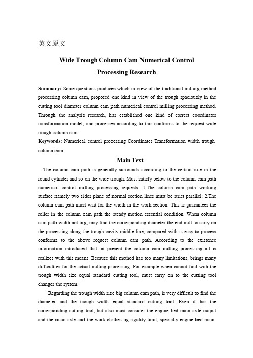
英文原文Wide Trough Column Cam Numerical ControlProcessing ResearchSummary: Some questions produces which in view of the traditional milling method processing column cam, proposed one kind in view of the trough spaciously in the cutting tool diameter column cam path numerical control milling processing method. Through the analysis research, has established one kind of correct coordinates transformation model, and processes according to this conforms to the request wide trough column cam.Keywords: Numerical control processing Coordinates Transformation width trough column camMain TextThe column cam path is generally surrounds according to the certain rule in the round cylinder and so on the wide trough. Must satisfy below to the column cam path numerical control milling processing requests: 1.The column cam path working surface namely two sides plane of normal section lines must be strict parallel; 2.The column cam path must wait for the width in the work section. This is guarantees the roller in the column cam path the steady motion essential condition. When column cam path width not big, may find the corresponding diameter the end mill to carry on the processing along the trough cavity middle line, compared with is easy to process conforms to the above request column cam path. According to the existence information introduced that, at present the column cam milling processing all is realizes with this means. Because this method has too many limitations, brings many difficulties for the actual milling processing. For example when cannot find with the trough width size equal standard cutting tool, must carry on to the cutting tool changes the system.Regarding the trough width size big column cam path, is very difficult to find the diameter and the trough width equal standard cutting tool. Even if has the corresponding cutting tool, but also must consider the engine bed main axle output and the main axle and the work clothes jig rigidity limit, specially engine bed mainaxle structure to cutting tool limit. For example the numerical control engine bed host axle neck is 7: 24 40 inner cones, uses for parts JT40 the tool system, then most greatly only can use φ20mm end mill (no matter straight handle bit holder). This regarding the trough width is the 38mm column cam (is processing cam which this article narrates) said is unable to process, must seek the new processing method.Under and analyzes the research according to the experience, introduced one kind is smaller than the cam path width end mill with the diameter to carry on the numerical control processing to the column cam path the method, calls it the width trough column cam numerical control processing.First, Processing craftThe column cam path is surrounds in the round cylinder and so on the width trough, when its processing often is bigger than 360°. along the circumference surface milling scopeIs suitable for with to have the numerical control rotary abutment the vertical numerical control milling machine to carry on the processing. According to the column cam actual structure, selects the belt key the spindle makes when the cam processing the radial direction and the week to the localization datum, makes the axial localization datum by the spindle ledge, and the nose thread contracts the column cam with the spindle in front of through the nut. The column cam axial and the radial direction size is generally big, in order to overcome because the bracket processes time the cutting force creates in the spindle distortion and the processing process produces inspires trembles, uses a supporting on the tailstock, withstands the spindle center bore with the numerical control turnplate rotation spool thread coaxial apex to make the auxiliary supporting.The column cam path base on each section usually is and so on deep, selects the flat base column end mill processing generally. Before the column cam milling processing usually is a solid circular cylinder, must pass through working procedure and so on slot, rough machining, half precision work, precision work; Because the trough cavity width is big, Therefore, except the trough working procedure and a rough machining working procedure part of knives positions path may along beside the trough cavity middle line production, other knife position paths then must bealong the trough cavity center alignment left, are right nearby two according to theCorresponding .Figure 1 column cam path two-dimensional developed viewSecond, Solution modelIn the column cam path numerical control processing, how extracts in each working procedure to process two sides surfaces the knife position path is key. Regarding the periphery on cam path, usually is launches first the round cylinder, extracts this working procedure in the XOS plane to process two sides surfaces the knife position path to launch curve XS; Then transforms through the coordinates, will launch the curve XS transformation will be on four coordinates engine beds knife position path. Under discusses no matter what in a processing working procedure launches curve XS the solution method, as well as production final knife position path coordinates transformation method.unches curve XS the solutionLike chart 2 shows, L o is the column cam path middle line, regarding the i working procedure, L li and L ri respectively the trough cavity which is going to process be this working procedure left, the right two sides surface launches the curve, this width is B i , processes the cutting tool radius is r (obviously 2r ≤ B i ), processes this cavity to be left, the right side knife position path launches the curve is CL li and CL ri ,supposes P o is in a trough cavity middle line spot, P o is the trough cavity middle line in the P o place law arrow, Then is left, the right knife position path launches in the curvecorresponding points pli and the pri computational method is:(1)Figure 2 column cam path two-dimensionaldeveloped viewP o along the trough cavity middle line migration, namely may extract this working procedure knife position path to launch curveXS in the XOS plane; According to the processing working procedure, changes in each working procedure in turn trough width Bi, then extracts the processing to need the trough cavity all knives position path to launch the curve.2.Along cam path middle line processing coordinates transformation methodAbove the computation is launches in the plane in the round cylinder to carry on, in order to extract the processing column cam path cavity the knife position path, must launch the plane in the curve to transform to the round cylinder in.The supposition rotating axis for circles Xaxis A axis, pi is in a knife position path knife position spot, it launches in the curve in the two-dimensional surface the coordinates for (x,s), on four coordinates engine beds coordinates is (x,y,z,a). Because the column cam path cavity usually is and so on deep, therefore, the z coordinates in establish after depths which needs to process, in the processing isinvariable; Below(2)In the formula, R is the column cam shaft radius. The previous type is the present universal use coordinates transformation formula, regarding uses the standard cutting tool to process the column cam along the cam path middle line milling is correct.3.Has the question analysis to the previous type in the width trough column cam processingWhen applies the previous type promotion in the width trough column camnumerical control processing, has had some questions actually through the coordinates transformation computation knife position path in the actual processing. Finished after the column cam path processing, in order to examine whether conforms to the requirement, with the diameter was equal to the column cam bowl examines has carries on the examination, discovered actually processes the trough width does not wait for the phenomenon which, has jams. The careful observation, processes originally on trough cavity plane of normal section not always inferior width rectangular trough, but sometimes is on under the width the narrow loudspeaker trough. In order to clarify reason, (2) expressed the coordinates transformation method to the formula to carry on the thorough analysis and the research.Like chart 3 shows, (1) may know by the formula, processes the trough cavity two sides surfaces knife position path on-line pl and the pr spot is by the trough cavity middle line in po equal-space bias but, (2) transforms after the formula, pl and the pr point correspondence corner is not equal to a P o corner, also is pl and pr corresponding cutter bar vector vlvl and po point correspondence cutter bar vector vovo not parallel, therefore, processes the trough cavity has become on under naturally the width the narrow loudspeaker trough, but is not on inferior width rectangular trough which needs. Supposes the section and the spool thread included angle for theta, the column cam shaft radius is R, cutter bar vector V l V l andV o V o theangle error is:δa=(B/2-r)sinθ/R (3)a)Cylinder cam slot sketch map b)The A-A cuts to face enlargethe sketch mapChart 3 Column cam path processing schematic drawing(3) may know by the formula, whenθ= 0°, when is the cam path middle line and the column spool thread vertical, the angle error is a zero, namely the trough cavity ison the inferior width rectangular mouth; When θ= 90°, when is the cam path middle line and the column spool thread parallel, the angle error achieved biggest, this time the trough cavity trumpet-shaped object phenomenon is most serious; When 0 <θ< 90°, along with θincreasing, angle error bigger, the trumpet-shaped object phenomenon is also more serious. The actual processing appears the phenomenon is completely consistent with the above analysis, this explained formula (3) the analysis is entirely accurate.4.Wide trough column cam numerical control processing coordinates transformation methodMay know by the above analysis, the formula (2) creates the cam path for on width under the narrow trumpet-shaped object main reason is, pl and the pr point correspondence corner is defers to these two, but sl and sr which selects own arc length value sl and sr calculates are is not equal to trough cavity central point po arc length value so. Therefore, if pl and the pr point correspondence corner defers to trough cavity central point po arc length value so to calculate, may eliminate this kind of loudspeaker trough phenomenon. According to this kind of mentality, again structure coordinates transformation formula.Two-dimensional launches in the plane in the round cylinder, supposes the trough cavity middle line to launch in the curve a spot is po (xo,So), processes on two sides surfaces to correspond the knife position spot in to launch in the curve the spotis pl (xl,sl) and pr (xr,pr), then, the coordinates transformation formulais:(4)The application formula (4) produces when knife position path processing column cam path, the result conforms to the above tentative plan completely, processes the column cam path already did not have on under the width the narrow loudspeaker trough phenomenon, but was the true on inferior wide rectangle trough.R e f ere n ce:1.Chang W C,Van Y T.Researching Design Trens for the Redesign of Product From Design Studies 2003.24(2):173-1802.Mou J,Liu C R.An error correction method for CNC machine tools using reference parts.transactions of NAMRE/SME,1994.3.Sutton G P.The machine tool task forch. Bal Harbour Bal Habour Hotel,1980.4.Gene F.Franklin Feedback control of Dynamis .systems,4E.译文:宽槽圆柱凸轮数控加工技术的研究摘要:针对传统铣削方法加工圆柱凸轮所产生的一些问题,提出了一种针对槽宽大于刀具直径的圆柱凸轮槽的数控铣削加工方法。
机械类数控车床外文翻译外文文献英文文献数控

数控加工中心技术发展趋势及对策原文来源:Zhao Chang-ming Liu Wang-ju (CNC Machining Process and equipment, 2002,China)一、摘要Equip the engineering level, level of determining the whole national economy of the modernized degree and modernized degree of industry, numerical control technology is it develop new developing new high-tech industry and most advanced industry to equip (such as information technology and his industry, biotechnology and his industry, aviation, spaceflight, etc. national defense industry) last technology and getting more basic most equipment. Numerical control technology is the technology controlled to mechanical movement and working course with digital information, integrated products of electromechanics that the numerical control equipment is the new technology represented by numerical control technology forms to the manufacture industry of the tradition and infiltration of the new developing manufacturing industry,Keywords:Numerical ControlTechnology, E quipment,industry二、译文数控技术和装备发展趋势及对策装备工业的技术水平和现代化程度决定着整个国民经济的水平和现代化程度,数控技术及装备是发展新兴高新技术产业和尖端工业(如信息技术及其产业、生物技术及其产业、航空、航天等国防工业产业)的使能技术和最基本的装备。
机械制造及自动化专业外文翻译--运动的综合,凸轮和齿轮
外文原文:Kinematic Synthesis ,Cams and Gears Mechanisms form the basic geometrical elements of many mechanical devices including automatic packaging machinery, typewriters, mechanical toys, textile machinery, and others. A mechanism typically is designed to create a desired motion of a rigid body relative to a reference member. Kinematic design, or kinematic syntheses, of mechanisms often is the first step in the design of a complete machine. When forces are considered, the additional problems of dynamics, bearing loads, stresses, lubrication, and the like are introduced, and the larger problem becomes one of machine design.A kinematician defined kinematics as “the study of the motion of mechanisms and methods of creating them.” The first part of this definition deals with kinematic analysis. Given a certain mechanism, the motion characteristics of its components will be determined by kinematic analysis. The statement of the tasks of analysis contains all principal dimensions of the mechanism, the interconnections of its links, and the specification of the input motion or method of actuation. The objective is to find the displacements, velocities, accelerations, shock or jerk (second acceleration) , and perhaps higher accelerations of the various members, as well as the paths described and motions performed by certain elements. In short, in kinematic analysis we determine the performance of a given mechanism. The second part of definition may be paraphrased in two ways:1. The study of methods of creating a given motion by means of mechanisms.2. The study of methods of creating mechanisms having a given motion.In either version, the motion is given and the mechanism is to be found. This is the essence of kinematic synthesis. Thus kinematic synthesis deals with the systematic design of mechanisms for a given performance. The area of synthesis may be grouped into two categories.1. Type synthesis. Given the required performance, what type of mechanism will be suitable? (Gear trains? Linkages? Cam mechanisms? ) Also, how many links should the mechanism have? How many degrees of freedom are required? What configuration id desirable? And so on. Deliberations involving the number of links and degrees of freedom are often referred to as the province of a subcategory of type synthesis called number synthesis.2. Dimensional synthesis. The second major category of kinematic synthesis is best defined by way of its objective: Dimensional synthesis seeks to determine the significant dimensions and the starting position of a mechanism of preconceived type for a specified task and prescribed performance.Significant dimensions mean link lengths or distances on binary, ternary, and so on, links, angles between axis, cam-contour dimensions and cam-follower diameters, eccentricities, gear rations, and so forth. A mechanism of preconceived type may be a slider-crank linkage, a four-bar linkage, a cam with flat follower, or a more complex linkage of a certain configuration defined topologically but not dimensionally. Thereare three customary tasks for kinematic synthesis: function generation, path generation and motion generation.In function generation mechanisms rotation or sliding motions of input and output links must be correlated. For an arbitrary function )(x f y =, a kinematic synthesis task may be to design a linkage to correlate input and output such that the input moves by x , the output moves by )(x f y = for the range 10+<<n x x x . In the case of rotary input and output, the angles of rotation ϕ and ψ are the linear analogs of x and y respectively. When the input link is rotated to a value of the independent x , the mechanism in a “black box” causes the output link to turn to the corresponding value of the dependent variable )(x f y =. This may be regarded as a simple case of a mechanical analog computer. A variety of different mechanisms cou ld be contained within the “black box”. However, the four -bar linkage is not capable of error-free generation of an arbitrary function and can match the function at only a limited number of precision points. It is widely used in industry because the four-bar linkage id simple to construct and maintain.In path generation mechanism a point on a “floating link” is to trace a path defined with respect to a fixed frame of reference. If the path points are to be correlated with either time or input-link positions, the task is called path generation with prescribed timing. An example of path generation mechanisms id a four-bar linkage designed to pitch a baseball or tennis ball. In this case the trajectory of point p would be such as to pick up a ball at a prescribed location and to deliver the ball along a prescribed path with prescribed timing for reaching a suitable throw-velocity and direction.There are many situations in the design of mechanical devises in which it is necessary either to guide a rigid body through a series of specified, finitely separated positions or to impose constraints on the velocity and/or acceleration of the moving body at a reduced number of finitely separated positions. Motion-generation or rigid-body guidance mechanism requires that an entire body be guided through a prescribed motion sequence. The body to be guided usually is a part of a floating link, of which not only is the path of a point p prescribed, but also the rotation of a line passing through the point and embedded in the body,. For instance, the line might represent a carrier link in a automatic machinery where a point located on the carrier link has a prescribed path while the carrier has a prescribed angular orientation. Prescribing the movement of the bucket for a bucket loader id another example of motion generation mechanisms, the path of tip of the bucket is critical since the tip must perform a scooping trajectory followed by a lifting and a dumping trajectory. The angular orientation of the bucket are equally important to ensure that load is dumped from the correct position.A cam is a convenient device for transforming one motion into another. Thismachine element has a curved or grooved surface which mates with a follower and imparts motion to it. The motion of the cam (usually rotation) is transformed into follower oscillation, translation, or both. Because of the various cam geometries and the large number of cam and follower combinations, the cam is an extremely versatile mechanical element. Although a cam and follower may be designed for motion, path, or function generation, the majority of applications utilize the cam and follower for function generation.The most common cam types according to cam shapes are: disk or plate translating (two-dimensional or planar), and cylindrical (three-dimensional or spatial) cams. Followers can be classified in several ways: according to follower motion, such as translation or oscillation; according to whether the translational (straight-line) follower motion is radial of offset from the center of the cam shaft; and according to the shape of the follower contact surface (e. g. , flat-face, roller, point (knife-edge), spherical, planar curved, or spatial-curved surface).In the case of a disk cam with a radial (in-line) translating roller follower the smallest circle that can be drawn tangent to the cam surface and concentric with the camshaft is the base circle. The tracer point is a point at the center of the roller center and the normal to the pitch curve. The pressure angle is the angle between the direction of the path of the roller center and the normal to the pitch curve through the center of the roller and is the complement of the transmission angle. Neglecting friction, this normal is collinear with the contact force between the cam and follower. As in a linkage, the pressure angle varies during the cycle and is a measure of the ability of the cam to transfer motive effort to the follower. A large pressure angle will produce an appreciable lateral force exerted on the stem of the follower, which, in the presence of friction, would tend to bind the follower in the guide.Numerous applications in automatic machinery require intermittent motion. A typical example will call for a rise-dwell-return and perhaps another dwell period of a specified number of degrees each, together with a required follower displacement measured in centimeters or degrees. The designer’s job is to lay out the cam accordingly. The first decision to be made is to choose the cam follower type. The specified application may dictate the combination of the cam and follower. Some factors that should enter into the decision are: geometric considerations, dynamic considerations, environmental considerations and economic matters. Once a type of cam and follower pair has been selected, the follower motion must be chosen. Therefore, the velocity, acceleration, and in some cases further derivatives of the displacement of the follower are of great importance.Gears are machine elements that transmit motion by means of successively engaging teeth. Gears transmit motion from one rotating shaft to another, or to a rack that translates. Numerous applications exist in which a constant angular velocity ratio (or constant torque ratio) must be transmitted between shafts. Based on the variety of gear types available, there is no restriction that the input and the output shafts need be either in-line or parallel. Nonlinear angular velocity ratios are also available by using noncircular gears. In order to maintain a constant angular velocity, the individual tooth profile must obey the fundamental law of gearing: for a pair of gears to transmita constant angular velocity ratio, the shape of their contacting profiles must be such that the common normal passes through a fixed point on the line of the centers.Any two mating tooth profiles that satisfy the fundamental law of gearing are called conjugate profiles. Although there are many tooth shapes possible in which a mating tooth could be designed to satisfy the fundamental law, only two are in general use: the cycloidal and involute profiles. The involute has important advantages: it is easy to manufacture and the center distance between a pair of involute gears can be varied without changing the velocity ratio. Thus chose tolerances between shafts are not required when utilizing the involute profile.There are several standard gear types. For applications with parallel shafts, straight spur gear, parallel helical, or herringbone gears are usually used. In the case of intersecting shafts, straight bevel of spiral bevel gears are employed. For nonintersecting and nonparallel shafts, crossed helical, worm, face, skew bevel or hypoid gears would be acceptable choices. For spur gears, the pitch circles of mating gears are tangent to each other. They roll on one another without sliding. The addendum is the height by which a tooth projects beyond the pitch circle (also the radial distance between the pitch circle and the addendum circle). The clearance is the amount by which the addendum (tooth height below the pitch circle) in a given gears exceeds the addendum of its mating gear. The tooth thickness is the distance across the tooth along the arc of the pitch circle while the tooth space is the distance between adjacent teeth along the arc of the pitch circle. The backlash is the amount by which the width of the tooth space exceeds the thickness of the engaging tooth at the pitch circle.中文译文:运动的综合,凸轮和齿轮机构是形成许多机械装置的基本几何结构单元,这些机械装置包括自动包装机、打印机、机械玩具、纺织机械和其他机械等。
宽槽圆柱凸轮数控加工的研究
宽槽圆柱凸轮数控加工的研究摘要针对传统铣削方法加工圆柱凸轮所产生的一些问题,提出了一种针对槽宽大于刀具直径的圆柱凸轮槽的数控铣削加工方法。
通过分析研究,建立了一种正确的坐标转换模型,并依此加工出符合要求的宽槽圆柱凸轮。
关键词:数控加工坐标转换宽槽圆柱凸轮圆柱凸轮槽一般是按一定规律环绕在圆柱面上的等宽槽。
对圆柱凸轮槽的数控铣削加工必须满足以下要求:1.圆柱凸轮槽的工作面即两个侧面的法截面线必须严格平行;2.圆柱凸轮槽在工作段必须等宽。
这是保证滚子在圆柱凸轮槽中平稳运动的必要条件。
当圆柱凸轮槽宽度不大时,可以找到相应直径的立铣刀沿槽腔中心线进行加工,比较容易加工出符合上述要求的圆柱凸轮槽。
据现有资料介绍,目前圆柱凸轮的铣削加工都是用这种办法来实现。
由于这种方法有太多的局限性,给实际铣削加工带来许多困难。
例如一旦找不到与槽宽尺寸相等的标准刀具时,就必须对刀具进行改制。
对于槽宽尺寸较大的圆柱凸轮槽,很难找到直径与槽宽相等的标准刀具。
即使有相应的刀具,还要考虑机床主轴输出功率及主轴和工装夹具刚度的限制,特别是机床主轴结构对刀具的限制。
例如数控机床主轴头为7∶24的40号内锥,配用JT40的工具系统,则最大只能使用φ20mm的立铣刀(不论直柄还是锥柄)。
这对于槽宽为38mm的圆柱凸轮(就是本文所叙述的加工凸轮)来说是无法加工的,必须寻求新的加工方法。
下面根据实践经验和分析研究,介绍一种用直径小于凸轮槽宽的立铣刀对圆柱凸轮槽进行数控加工的方法,称之为宽槽圆柱凸轮的数控加工。
一、加工工艺圆柱凸轮槽是环绕在圆柱面上的等宽槽,其加工时沿圆周表面铣削的范围往往大于360°,适于用带有数控回转台的立式数控铣床进行加工。
根据圆柱凸轮的实际结构,选用带键的心轴作凸轮加工时径向和周向定位基准,以心轴的台肩作轴向定位基准,并用心轴前端部的螺纹通过螺母压紧圆柱凸轮。
圆柱凸轮的轴向和径向尺寸一般较大,为了克服由于悬臂加工时切削力所造成的心轴变形和加工过程中产生的振颤,使用一个支承于尾座上的、与数控转台的回转轴线同轴的顶尖顶住心轴中心孔作辅助支承。
关于凸轮设计的外文翻译-其他专业
关于凸轮的外文资料ELEMENTS OF CAM DESIGNHow to plan and produce simple but efficient cams for petrol engines and other mechanismsCams are among the most versatile mechanisms available.A cam is a simple two-member device.The input member is the cam itself,while the output member is called the follower.Through the use of cams,a simple input motion can be modified into almost any conceivable output motion that is desired.Some of the common applications of cams are——Camshaft and distributor shaft of automotive engine——Production machine tools——Automatic record players——Printing machines——Automatic washing machines——Automatic dishwashersThe contour of high-speed cams (cam speed in excess of 1000 rpm) must be determined mathematically.However,the vast majority of cams operate at low speeds(less than 500 rpm) or medium-speed cams can be determined graphically using a large-scale layout.In general,the greater the cam speed and output load,the greater must be the precision with which the cam contour is machined.Cams in some form or other are essential to the operation of many kinds of mechanical devices. Their best-known application is in the valve-operating gear of internal combustion engines, but they play an equally important part in industrial machinery, from printing presses to reaping machines.In general, a cam can be defined as a projection on the face of a disc or the surface of a cylinder for the purpose of producing intermittent reciprocating motion of a contacting member or follower. Most cams operate by rotary motion, but this is not an essential condition and in special cases the motion may be semi-rotary,oscillatoryor swinging. Even straight-line motion of the operating member is possible, though the term cam may not be considered properly applicable in such circumstances.Most text books on mechanics give some information on the design of cams and show examples of cam forms plotted to produce various orders of motion. Where neither the operating speed nor the mechanical duty is very high, there is a good deal of latitude in the nermissible design of the cam and it is only necessary to avoid excessively steep contours or abrupt changes which would result in noise, impact shock, and side pressure on the follower. But, with increase of either speed or load, much more exacting demands are made on the cam, calling for the most careful design and, at very high speed, the effect of inertia on the moving parts is most pronounced, so that the further factors of acceleration and rate of lift have to be taken into account and these are rarely dealt with in any detail in the standard text books.The design of the cam follower is also of great importance and bears a definite relation to the shape of the cam itself. This is because the cam cannot make contact with the follower at a single fixed point. Surface contact is necessary to distribute load and avoid excess wear, thus the cam transmits its motion through various points of location on the follower, depending on the shape of the two complementary cams for operating . engine valves present specially difficult problems in design. In the case of racing engines, both the load and speed may be regarded as extreme, because in many engines the rate at which the valves can be effectively controlled is the limiting factor in engine performance. In some respects, cam design of miniature engines is simplified by reason of their lighter working parts (and consequent less inertia) but on the other hand, working friction is usually greater and rotational speeds are generally considerably higher than in full-size practice.In the many designs for small four-stroke engines which I have published, I have sought to simplify valve operation and to provide designs for cams which can be simply and accurately produced with the facilities of the amateur workshop. Numerous engine designs which have been submitted to me by readers have contained errors in the valve gear and particularly in the cams and in view of prevalent misconceptions in the fundamental principles of these items, I am givingsome advice on the matter which I trust will help individual designers to obtain the best results from their engines. There have been many engines built with cams of thoroughly bad design but which, in spite of this, have produced results more or less satisfactory to their constructors. It may be said that within certain limits of speed one can get away with murder but in no case can an engine perform efficiently with badly designed cams, or indeed errors in any of its working details. This article is concerned mainly with the design of cams for operating the valves of . engines and, in order to avoid any confusion of terms, Fig. 1 shows the various parts of a cam of this type and explains their functions. The circular, concentric portion of the cam, which has no operative effect, is known as the base circle: the humy of the cam (shown shaded) is known as the lobe, and the flanks on either side rise from the base circle to the nose, which is usually may be defined as the difference between the radius of the base circle and that of the nose. the anele enclosed between the points where the flanks join the base circle is termed the angular ‘period, representing the proportion of the full cycle during which the cam operates the valve gear. In Fig. 2, typical examples of cams used in . engines are illustrated. The tangent cam, A, has dead straightflanks-which as the name implies form tangents to the base circle. This type of cam is easy to design and produce, the simplest method of machining being by a circular milling process forming a concentric surface on the base circle and running straight out tangentially where the flanks start and finish. It can also be produced by filing and I have in the past described how to make it with the aid of a roller filing rest in the lathe, in conjunction with indexing gear to locate the flank angles.Tangent cams can only work efficiently in conjunction with a convex curved follower, as this is the only way in which the flank can be brought progressively and smoothly into action. Some time ago an engine was described having tangent cams in conjunction with flat followers. This was not intended for extremely high speed and very likely produced all the power required of it, but it is quite clear that the flat face of the tangent cam. On engaging the flat tappet-over the full length of the flank all at once, must produce an abrupt slapping action which is noisy, inefficient and destructive in the long run. Rollers are often used as followers with tangent cams andare satisfactory in respect of their shape, but the idea of introducing rolling motion at this point is not as good as it seems at first sight, because it merely transfers the sliding friction to a much smaller area--that of the pivot pin. It is possible in some cases, however, to use a ball or roller race for the follower and this, at any rate, has the merit of distributing and equalizing the wearing surface.Tangent cams have been used with a certain degree of success forhigh-performance-engines and were at one time popular on racing motorcycle engines, though usually with some slight modification of shape-often “ designed ” by the tuner with the aid of .a Carborundum slip! Their more common application, however, has been on gas and oil engines running at relatively slow speeds, where they work wellin contact with rollers attached to the ends of the valve rockers. Cams with convex flanks are extensively used in motor cars and other mass-produced engines. One important advantage in this respect is that they are suited to manufacture in quantity by a copying process from accurately formed master cams. The fact that hat-based tappets can be used also favours quantity production and they can be designed to work fairly silently. The contour of the flank can be plotted so that violent changes in the acceleration of the cam are avoided and, more important still, the tappet will follow the cam on the return motion without any tendency to bounce or float at quite high speeds. In such cases, it may be necessary to introduce compound curves which are extremely difficult to copy on a small scale, but cams made with flanks formmg true circular arcs will give reasonably efficient results, and are very easily produced in any scale: Concave-flanked cams.Comparatively few examples of concave-flanked cams (Fig. 2c) are to be seen nowadays, though they have been used extensively in the past with the idea of obtaining the most rapid opening and closing of the valves. Theoretically, they can be designed to produce constant-acceleration, but in practice they render valve control very difficult at high speed and their fierce angle of attack produces heavy side pressure on the tappet. The concave flank must always have a substantially greater radius than the follower, or a slapping action like that of a tangent cam on a flat follower is produced.The shape of the nose in most types of cams is dictated mainly by the need to decelerate the follower as smoothly as possible. It is one thing to design it in such a way that ideal conditions are obtained, and quite another to ensure in practice that the follower retains close contact with the cam. If the radius of the nose is too small, the follower will bounce and come down heavily on the return flank of the cam and,. if too great, valve opening efficiency will be reduced.Of the three types of cams, A, B and C, which all have identically equal lift and angular period, the lobe of B encloses the smallest area, and on first sight it might appear that it is the least efficient in producing adequate valve opening, or mean lift area, but owing to the use of a flat based tappet, its lift characteristics are not very different from those of a tangent cam with round-based tappet, and not necessarily inferior to those of a concave-flank cam.Unsymmetrical camsIt is not common to make the two flanks of a cam of different contours to produce some particular result which the designer may consider desirable. In some cases, the object is to produce rapid opening and gradual closing, but sometimes the opposite effect is preferred. When all things are considered, however, most attempts to monkey about with cam forms lead to complications which may actually defeat their own object, at least at really high speeds.In many engines, particularly those of motorcycles, the cams operate the valves through levers or rockers which move in an arc instead of in a straight line, as in the orthodox motor car tappet. This may be mechanically efficient, but it modifies the lift characteristic of the cam, as the point at which the latter transmits motion to the follower varies in relation to the radius of the lever arm, (Fig. 3).With the cam rotating in a clockwise direction, the effective length of the lever will be greater in the position.A during valve opening than in positionB during closing, as indicated by dimensions X and Y. This amounts to the same as using an unsymmetrical cam, and in the example shown, would result in slow opening and rapid closing of the valve, or vice versa if either the direction of r otation of the cam, or the relative “hand ” of thelever, is reversed. The shorter the lever, the greater the discrepancy in the rate of movement, Neither the unsymmetrical cam form nor the pivoted lever is condemned as bad design, but I have sought to avoid them in most of the engines I have designed because they are a complicating factor in what is already a very involved problem, and by keeping to fairly simple cams and straight-line tappets, one can be assured that there are not too many snags.The employment of cams with flanks of true circular arc has enabled me to devise means of producing them on the lathe without elaborate attachments and, what is more important still, to produce an entire set of cams for a multi-cylinder engine in correct angular relation to each other by equally simple means. There is no doubt whatever that these methods have enabled many engine constructors (some without previous experience) to tackle successfully a problem which would otherwise have been formidable, to say the least.Many designers have attempted to improve valve efficiency by designing cams which hold the valve at maximum opening for as long a period as possible. This is done by providing dwell or, in other words, making the top of the lobe concentric with the cam axis over a certain angular distance in the center of its lift. To do this, however, it is necessary to make the flanks excessively steep, thus producing heavy side thrust on the tappet, and making control at high speed more difficult, (Fig. 4A).A little consideration, however, will show that the same result can be achieved, with much less mechanical difficulty, by lifting the valve somewhat higher at an easier rate, as shown at B. This avoids the need for sudden acceleration and deceleration of the tappet and promotes flow efficiency of the valve. The shaded portions of the two cams show the differences in the area of the lobe, showing that nothing is really gained by the dwell. Factors in efficiency High valve lift is a desirable feature, but only if it can be obtained without making extra difficulties in controlling the valve. The maximum port area of a valve is obtained when the lift is equal to one-fourth of the seat diameter, but owing to the baffling effect on the valve head, a higher lift is better for flow efficiency-if it is practicable.中文翻译凸轮设计的基本内容如何为汽油发动机和其他机械设计和生产简单有效的凸轮凸轮是被应用的最广泛的机械结构之一。
凸轮设计外文翻译参考文献
外文文献翻译(含:英文原文及中文译文)英文原文Failure Analysis, Dimensional Determination And Analysis , ApplicationsOf CamsINTRODUCTIONIt is absolutely essential that a design engineer know how and why parts fail so that reliable machines that require minimum maintenance can be designed. Sometimes a failure can be serious, such as when a tire blows out on an automobile traveling at high speed. On the other hand, a failure may be no more than a nuisance. An example is the loosening of the radiator hose in an automobile cooling system. The consequence of this latter failure is usually the loss of some radiator coolant, a condition that is readily detected and corrected. The type of load a part absorbs is just as significant as the magnitude . Generally speaking , dynamic loads with direction reversals cause greater difficulty than static loads, and therefore, fatigue strength must be considered. Another concern is whether the material is ductile or brittle. For example, brittle materials are considered to be unacceptable where fatigue is involved.Many people mistakingly interpret the word failure to mean the actual breakage of a part . However , a design engineer must consider abroader understanding of what appreciable deformation occurs. A ductile material, however will deform a large amount prior to rupture. Excessive deformation, without fracture, may cause a machine to fail because the deformed part interferes with a moving second part . Therefore , a part fails(even if it has not physically broken)whenever it no longer fulfills its required function . Sometimes failure may be due to abnormal friction or vibration between two mating parts. Failure also may be due to a phenomenon called creep, which is the plastic flow of a material under load at elevated temperatures. In addition, the actual shape of a part may be responsible for failure . For example , stress concentrations due to sudden changes in contour must be taken into account . Evaluation of stress considerations is especially important when there are dynamic loads with direction reversals and the material is not very ductile.In general, the design engineer must consider all possible modes of failure, which include the following.—— Stress—— Deformation—— Wear—— Corrosion—— Vibration—— Environmental damage—— Loosening of fastening devicesThe part sizes and shapes selected also must take into account many dimensional factors that produce external load effects , such as geometric discontinuities , residual stresses due to forming of desired contours, and the application of interference fit joints.Cams are among the most versatile mechanisms available . A cam is a simple two-member device. The input member is the cam itself, while the output member is called the follower. Through the use of cams, a simple input motion can be modified into almost any conceivable output motion that is desired. Some of the common applications of cams are : —— Camshaft and distributor shaft of automotive engine—— Production machine tools—— Automatic record players—— Printing machines—— Automatic washing machines—— Automatic dishwashersThe contour of high-speed cams (cam speed in excess of 1000 rpm) must be determined mathematically. However , the vast majority of cams operate at low speeds(less than 500 rpm) or medium-speed cams can be determined graphically using a large-scale layout . In general, the greater the cam speed and output load, the greater must be the precision with which the cam contour is machined.DESIGN PROPERTIES OF MATERIALSThe following design properties of materials are defined as they relate to the tensile test .Static Strength. The strength of a part is the maximum stress that the part can sustain without losing its ability to perform its required function. Thus the static strength may be considered to be approximately equal to the proportional limit , since no plastic deformation takes place and no damage theoretically is done to the material.Stiffness . Stiffness is the deformation-resisting property of a material. The slope of the modulus line and , hence , the modulus of elasticity are measures of the stiffness of a material .Resilience . R esilience is the property of a material that permits it to absorb energy without permanent deformation. The amount of energy absorbed is represented by the area underneath the stress-strain diagram within the elastic region.Toughness . Resilience and toughness are similar properties. However , toughness is the ability to absorb energy without rupture. Thus toughness is represented by the total area underneath the stress-strain diagram , as depicted in Figure 2. 8b . Obviously , the toughness and resilience of brittle materials are very low and are approximately equal. Brittleness . A brittle material is one that ruptures before any appreciable plastic deformation takes place. Brittle materials are generally considered undesirable for machine components because they are unable to yieldlocally at locations of high stress because of geometric stress raisers such as shoulders, holes , notches , or keyways.Ductility . A ductility material exhibits a large amount of plastic deformation prior to rupture. Ductility is measured by the percent of area and percent elongation of a part loaded to rupture. A 5%elongation at rupture is considered to be the dividing line between ductile and brittle materials.Malleability . Malleability is essentially a measure of the compressive ductility of a material and, as such, is an important characteristic of metals that are to be rolled into sheets .Hardness . The hardness of a material is its ability to resist indentation or scratching . Generally speaking, the harder a material, the more brittle it is and, hence , the less resilient. Also , the ultimate strength of a material is roughly proportional to its hardness .Machinability . M achinability is a measure of the relative ease with which a material can be machined. In general, the harder the material, the more difficult it is to machine.Figure 2.8COMPRESSION AND SHEAR STATIC STRENGTHIn addition to the tensile tests, there are other types of static load testing that provide valuable information.Compression Testing. Most ductile materials have approximately thesame properties in compression as in tension. The ultimate strength, however , can not be evaluated for compression . As a ductile specimen flows plastically in compression, the material bulges out , but there is no physical rupture as is the case in tension. Therefore , a ductile material fails in compression as a result of deformation, not stress.Shear Testing. Shafts, bolts , rivets , and welds are located in such a way that shear stresses are produced. A plot of the tensile test. The ultimate shearing strength is defined as the stress at which failure occurs. The ultimate strength in shear, however , does not equal the ultimate strength in tension . For example , in the case of steel , the ultimate shear strength is approximately 75% of the ultimate strength in tension. This difference must be taken into account when shear stresses are encountered in machine components.DYNAMIC LOADSAn applied force that does not vary in any manner is called a static or steady load. It is also common practice to consider applied forces that seldom vary to be static loads. The force that is gradually applied during a tensile test is therefore a static load.On the other hand, forces that vary frequently in magnitude and direction are called dynamic loads. Dynamic loads can be subdivided to the following three categories. Varying Load. With varying loads , the magnitude changes , but the direction does not . For example, the loadmay produce high and low tensile stresses but no compressive stresses .Reversing Load. In this case, both the magnitude and direction change. These load reversals produce alternately varying tensile and compressive stresses that are commonly referred to as stress reversals.Shock Load. This type of load is due to impact. One example is an elevator dropping on a nest of springs at the bottom of a chute. The resulting maximum spring force can be many times greater than the weight of the elevator, The same type of shock load occurs in automobile springs when a tire hits a bump or hole in the road.FATIGUE FAILURE-THE ENDURANCE LIMIT DIAGRAMThe test specimen in Figure 2.10a . , after a given number of stress reversals will experience a crack at the outer surface where the stress is greatest. The initial crack starts where the stress exceeds the strength of the grain on which it acts. This is usually where there is a small surface defect, such as a material flaw or a tiny scratch. As the number of cycles increases, the initial crack begins to propagate into a continuous series of cracks all around the periphery of the shaft . The conception of the initial crack is itself a stress concentration that accelerates the crack propagation phenomenon . Once the entire periphery becomes cracked , the cracks start to move toward the center of the shaft . Finally , when the remaining solid inner area becomes small enough , the stress exceeds the ultimate strength and the shaft suddenly breaks. Inspection of the break reveals avery interesting pattern, as shown in Figure 2.13. The outer annular area is relatively smooth because mating cracked surfaces had rubbed against each other . However , the center portion is rough, indicating a sudden rupture similar to that experienced with the fracture of brittle materials.This brings out an interesting fact. When actual machine parts fail as a result of static loads , they normally deform appreciably because of the ductility of the material.Thus many static failures can be avoided by making frequent visual observations and replacing all deformed parts. However , fatigue failures give to warning. Fatigue fail mated that over 90% of broken automobile parts have failed through fatigue.The fatigue strength of a material is its ability to resist the propagation of cracks under stress reversals. Endurance limit is a parameter used to measure the fatigue strength of a material . By definition, the endurance limit is the stress value below which an infinite number of cycles will not cause failure.Let us return our attention to the fatigue testing machine in Figure 2.9. The test is run as follows:A small weight is inserted and the motor is turned on. At failure of the test specimen , the counter registers the number of cycles N, and the corresponding maximum bending stress is calculated from Equation 2.5. The broken specimen is then replaced by an identical one, and an additional weight is inserted to increase the load. Anew value of stress is calculated, and the procedure is repeated until failure requires only one complete cycle . A plot is then made of stress versus number of cycles to failure. Figure 2.14a shows the plot, which is called the endurance limit or S-N curve. Since it would take forever to achieve an infinite number of cycles, 1 million cycles is used as a reference. Hence the endurance limit can be found from Figure 2.14a by noting that it is the stress level below which the material can sustain 1 million cycles without failure.The relationship depicted in Figure 2.14 is typical for steel, because the curve becomes horizontal as N approaches a very large number. Thus the endurance limit equals the stress level where the curve approaches a horizontal tangent. Owing to the large number of cycles involved , N is usually plotted on a logarithmic scale, as shown in Figure 2.14b. When this is done , the endurance limit value can be readily detected by the horizontal straight line . For steel , the endurance limit equals approximately 50% of the ultimate strength . However , if the surface finish is not of polished equality , the value of the endurance limit will be lower. For example, for steel parts with a machined surface finish of 63 microinches ( μin. ) , the percentage drops to about 40%. For rough surfaces (300μin. or greater), the percentage may be as low as 25%.The most common type of fatigue is that due to bending. The next most frequent is torsion failure, whereas fatigue due to axial loads occursvery seldom. Spring materials are usually tested by applying variable shear stresses that alternate from zero to a maximum value , simulating the actual stress patterns.In the case of some nonferrous metals , the fatigue curve does not level off as the number of cycles becomes very large . This continuing toward zero stress means that a large number of stress reversals will cause failure regardless of how small the value of stress is. Such a material is said to have no endurance limit. For most nonferrous metals having an endurance limit, the value is about 25% of the ultimate strength.EFFECTS OF TEMPERATURE ON YIELD STRENGTH AND MODULUS OF ELASTICITYGenerally speaking , when stating that a material possesses specified values of properties such as modulus of elasticity and yield strength, it is implied that these values exist at room temperature. At low or elevated temperatures, the properties of materials may be drastically different. For example, many metals are more brittle at low temperatures. In addition , the modulus of elasticity and yield strength deteriorate as the temperature increases . Figure 2.23 shows that the yield strength for mild steel is reduced by about 70% in going from room temperature to 1000o F .Figure 2.24 shows the reduction in the modulus of elasticity E for mild steel as the temperature increases. As can be seen from the graph, a 30% reduction in modulus of elasticity occurs in going from roomtemperature to 1000o F . In this figure, we also can see that a part loaded below the proportional limit at room temperature can be permanently deformed under the same load at elevated temperatures.CREEP: A PLASTIC PHENOMENONTemperature effects bring us to a phenomenon called creep, which is the increasing plastic deformation of a part under constant load as a function of time. Creep also occurs at room temperature, but the process is so slow that it rarely becomes significant during the expected life of the temperature is raised to 300o C or more , the increasing plastic deformation can become significant within a relatively short period of time . The creep strength of a material is its ability to resist creep, and creep strength data can be obtained by conducting long-time creep tests simulating actual part operating conditions. During the test , the plastic strain is monitored for given material at specified temperatures.Since creep is a plastic deformation phenomenon , the dimensions of a part experiencing creep are permanently altered. Thus , if a part operates with tight clearances, the design engineer must accurately predict the amount of creep that will occur during the life of the machine. Otherwise , problems such binding or interference can occur. Creep also can be a problem in the case where bolts are used to clamp tow parts together at elevated temperatures. The bolts, under tension, will creep as a function of time . Since the deformation is plastic, loss of clamping forcewill result in an undesirable loosening of the bolted joint. The extent of this particular phenomenon, called relaxation, can be determined by running appropriate creep strength tests.SUMMARYThe machine designer must understand the purpose of the static tensile strength test . This test determines a number of mechanical properties of metals that are used in design equations. Such terms as modulus of elasticity, proportional limit, yield strength, ultimate strength, resilience , and ductility define properties that can be determined from the tensile test.Dynamic loads are those which vary in magnitude and direction and may require an investigation of the machine part’s resistance to failure. Stress reversals may require that the allowable design stress be based on the endurance limit of the material rather than on the yield strength or ultimate strength.Stress concentration occurs at locations where a machine part changes size, such as a hole in a flat plate or a sudden change in width of a flat plate or a groove or fillet on a circular shaft. Note that for the case of a hole in a flat or bar, the value of the maximum stress becomes much larger in relation to the average stress as the size of the hole decreases . Methods of reducing the effect of stress concentration usually involve making the shape change more gradual.Machine parts are designed to operate at some allowable stress below the yield strength or ultimate strength. This approach is used to take care of such unknown factors as material property variations and residual stresses produced during manufacture and the fact that the equations used may be approximate rather that exact . The factor of safety is applied to the yield strength or the ultimate strength to determine the allowable stress. Temperature can affect the mechanical properties of metals. Increases in temperature may cause a metal to expand and creep and may reduce its yield strength and its modulus of elasticity . If most metals are not allowed to expand or contract with a change in temperature , then stresses are set up that may be added to the stresses from the load. This phenomenon is useful in assembling parts by means of interference fits. A hub or ring has an inside diameter slightly smaller than the mating shaft or post. The hub is then heated so that it expands enough to slip over the shaft. When it cools, it exerts a pressure on the shaft resulting in a strong frictional force that prevents loosening.中文译文失效分析,尺寸确定与分析,凸轮的应用引言设计工程师知道如何以及为什么部件出现故障是绝对必要的,这样可以设计出需要最少维护的可靠机器。
圆柱凸轮数控加工工艺技术研究
加 圆柱 凸轮 廓 面检 测 等 工 艺环 节进 行 了分析 研 究 , 在 DMU7 V加 工 中心 上 并 0
完成 了圆柱 凸轮 的数 控 加 工 , 高 了圆柱 凸轮 的加 工 品质 。 提
关 键 词 : 柱 凸 轮 数 控 加 工 工 艺 展 成 法 圆
圆柱 凸轮 廓 面属 于 空 间复 杂 曲 面 , 的加 工 品质 的 高 它 低直 接影 响 圆柱 分 度 凸轮 机构 ( 1 的 性 能 。长 期 以来 , 图 ) 我 们往 往 探 讨 和重 点分 析 的是 如 何 利用 各 种 先 进 制 造 技 术 ( A /A N C DC M, C技 术 等 ) 提 高 圆柱 凸轮 的加 工 品 质 , 来 实
图 2 展 成 法加 工 示 意 图
作 轴 向 定位 基准 ,并 用 心 轴 前端 部 的螺 纹 通 过 螺母 压 紧
维普资讯
现 造 术与 备 代制 技 装
圆 柱凸 轮 。
2 7 期总 8期 0 第5 第1 0 0
减 少加 工 误差 。 26 圆柱 凸轮 的廓 形 检测 .
求 的圆柱 凸 轮槽 。
圆柱 凸轮槽 是 环 绕在 圆柱 面上 的等 宽槽 , 加 工 时 沿 其 圆周 表 面铣 削 的范 围往 往 大 于 3 0 , 于用 带 有 数 控 回 6。 适 转 台 的立 式 数 控铣 床进 行 加 工 。 我们 采 用 悬 臂 加 工 的 方 式, 即在 工作 台上 安 装完 圆柱 凸 轮 , 工作 台绕 B轴 旋 转 将 9 。 立起 来 加工 。根 据 圆柱 凸 轮 的实 际结 构 , 用带 键 的 0 选 心 轴 作 凸 轮 加工 时 径 向和 周 向定 位 基 准 , 以心 轴 的 台 肩
正 刀 位轨 迹 ,对 影 响 圆 柱 凸 轮 加工 品质 的因 素进 行 有 效
机电专业毕业设计中英文翻译资料--圆柱凸轮的设计和加工
机电专业毕业设计中英文翻译资料--圆柱凸轮的设计和加工英文资料翻译英文原文:Design and machining of cylindrical cams with translating conical followersBy DerMin Tsay and Hsien Min WeiA simple approach to the profile determination and machining ofcylindrical cams with translating conical followers is presented .On thebasis of the theory of envelopes for a 1-parameter family of surfaces,acam profile with a translating conical follower can be easily designedonce the follower-motion program has been given .In the investigation ofgeometric characteristics ,it enables the contact line and the pressureangle to be analysed using the obtained analytical profile expressions .Inthe process of machining ,the required cutter path is provided for atapered endmill cutter ,whose size may be identical to or smaller thanthat of the conical follower .A numerical example is given to illustrate theapplication of the procedure .Keywords : cylindrical cams, envelopes , CAD/CAMA cylindrical cam is a 3D cam which drives its follower in a groove cut onthe periphery of a cylinder .The follower, which is either cylindrical orconical, may translate or oscillate. The cam rotates about its longitudinalaxis, and transmits a transmits a translation or oscillation displacementto the follower at the same time. Mechanisms of this type have long beenused in many devices, such as elevators, knitting machines, packingmachines, and indexing rotary tables.In deriving the profile of a 3Dcam, various methods have used.Dhande et al.1 and Chakraborty and dhande2 developed a method tofind the profiles of planar and spatial cams. The method used is based onthe concept that the common normal vector and the relative velocityvector are orthogonal to each other at the point of contact between thecam and the follower surfaces. Borisov3 proposed an approach to theproblem of designing cylindrical-cam mechanisms by a computeralgorithm. By this method, the contour of a cylindrical cam can beconsidered as a developed linear surface, and therefore the designproblem reduces to one of finding the centre and side profiles of the camtrack on a development of the effective cylinder. Instantaneousscrew-motion theory4 has been applied to the design of cam mechanisms.Gonzalez-Palacios et al.4 used the theory to generate surfaces of planar,spherical, and spatial indexing cam mechanisms in a unified framework.Gonzalez-Palacios and Angeles5 again used the theory to determine thesurface geometry of spherical cam-oscillating roller-follower mechanisms.Considering machining for cylindrical cams by cylindrical cutters whosesizes are identical to those of the followers, Papaioannou and Kiritsis6proposed a procedure for selecting the cutter step by solving aconstrained optimization problem.The research presented in this paper shows q new, easy procedure fordetermining the cylindrical-cam profile equations and providing thecutter path required in the machining process. This is accomplished bythe sue of the theory of envelopes for a 1-parameter family of surfacesdescribed in parametric form7 to define the cam profiles. Hanson andChurchill8 introduced the theory of envelopes for a 1-parameter familyof plane curves in implicit form to determine the equations of plate-camprofiles Chan and Pisano9 extended the envelope theory for the geometryof plate cams to irregular-surface follower systems. They derived ananalytical description of cam profiles for general cam-follower systems,and gave an example to demonstrate the method in numerical form.Using the theory of envelopes for a 2-parameter family of surfaces inimplicit form, Tsay and Hwang10 obtained the profile equations ofcamoids. According to the method, the profile of a cam is regarded as anenvelope for the family of the follower shapes in different cam-followerpositions when the cam rotates for a complete cycle.THEORY OF ENVELPOES FOR 1-PARAMETER FAMILY OFSURFACES IN PARAMETRIC FORMIn 3D xyz Cartesian space , a 1-parameter family of surfaces can be givenin parametric form as()12,,r r μμζ= (1)w here ζ is the parameter of the family, and u1, u 2, are theparameters for a particular surface of the family. Then, the envelope forthe family described in Equation 1 satisfies equation 1 and the followingEquation:0211=∂∂⨯∂∂⨯∂∂ςμμr r r (2) where the right-hand side is a constant zero7. Litvin showed the provingprocess of the theorem in detail.If we can solve Equation2 and substitute into equation1to eliminateone of the three parameters u1, u 2, and ζ , we may obtain the envelope inparametric form. However, one important thing should be pointed outhere. Equations 1 and 2 can also be satisfied by the singular points ofsurfaces described below I the family, even if they do not belong to theenvelope. Points which are regular points of surfaces of the family andsatisfy Equation 2 lie on the envelope.The condition for the singular points of a surface is discussed here.. aparametric representation of a surface is()12,r r μμ= (3)where u1 and u 2 are the parameters of the surface. A point of thesurface that corresponds to120r r μμ∂∂⨯=∂∂ in a given parameterization is called a singular point of theparameterization. A point of a surface is called singular if it is singularfor every parameterization of the surface7. A point that is singular in oneparameterization of a surface may not be singular in otherparameterizations.For a fixed value of ζ, equations 1 and 2 represent, in general, a curveon the surface which corresponds to this value of the parameter. If this isnot a line of singular points, the curve slso lies on the envelope. Thesurface and the envelope are tangent to each other along this curve. Suchcurves are called characteristic lines of the family7. they can be used tofind the contact lines between the surfaces of the cylindrical cam and thefollower.THEORY OF ENVELOPES FOR DETERMINATION OFCYLINDRICAL-CAM PROFILESOn the basis of the theory of envelopes, the profile of a cylindrical camcan be regarded as the envelope of the family of follower surfaces inrelative positions between the cylindrical cam and the follower while themotion of cam proceeds. In such a condition, the input parameters of thecylindrical cam serve as the family parameters. Because the cylindricalor conical follower surface can be expressed in parametric form withoutdifficulty, the theory of envelopes for a 1-parameter of surfacesrepresented in parametric form (see equations 1 and 2) is used indetermining the analytical equations of cylindrical-cam profiles. Asstated in the last section, a check for singular points on the followersurface is always needed.Figure 1a shows a cylindrical-cam mechanism with a translatingconical follower. The axis which the follower translates along is parallelto the axis of rotation of the cylindrical cam. a is the offset, that is, thenormal distance between the longitudinal axis of the cam and that of thefollower. R and L are the radius and the axial length of the cam,respectively.The rotation angle of the cylindrical cam is Ф2 about its axis. Thedistance traveled by the follower is s1 , which is a function of parameterФ2 ,as follows:()112S S φ= (4)The displacement relationship (see equation 4 ) for the translatingfollower is assumed to be given.In figure 1b, the relative position of the follower when the follower movesis shown. The follower is in the form of a frustum of a cone. Thesemicone angle is α, and the smallest radius is r. δ1 is the height, and μ isthe normal distance from the xz plane to the base of the cone. The fixedcoordinate system Oxyz is located in such a way that the z axis is alongthe rotation axis of the cam, and the y axis is parallel to the longitudinalaxis of the conical follower. the unit vectors of the x axis, y axis and z axisare i , j and k, respectively.By the use of the envelope technique to generate the cylindrical-camprofile, the cam is assumed to be stationary. The follower rotates aboutthe dam axis in the opposite direction. It is assumed that the followerrotates through an angle Ф2 about the axis. At the same time, thefollower is transmitted a linear displacement s1 by the cam, as shown inFigure 1b. Consequently using the technique, if we introduce θ and δ astwo parameters for the follower surface, the family of the followersurfaces can be described as()()()()()()2222222,,cos sin tan cos cos sin cos tan cos sin 1tan sin r r a r ia r js r kθδφφμδφδαθφφμδφδαθφδαθ==++-+⎡⎤⎣⎦+-++++⎡⎤⎣⎦+--+⎡⎤⎣⎦ (5)where0≤θ<2piAnd ф2 is the independent parameter of the cam motion.Referring to theory of envelopes for surfaces represented inparametric form (see equations 1and 2), we proceed with the solvingprocess by finding()()()()2222tan cos cos sin tan cos sin cos tan sin r r r i j kδαθφδαθδθφφαθ∂∂⨯=++⎡⎤⎣⎦∂∂+-++⎡⎤⎣⎦ (6)There are no singular points on the family of surfaces, since(r +δtanα) >0 in actual applications. The profile equation satisfies equation 5 and the following equation:()()(){}2'1sec tan cos sin tan sin cos cos sin 0r r r r s r a αδαθδφαθδααμδαθα∂∂∂⨯=-+⨯∂∂∂+-+-++⎡⎤⎣⎦=(7)Where 1'12ds s d φ=or()22212tan E E F G θ--±+-= ⎪⎝⎭ (8) Where ()()'1cos tan sin cos sin E s F r G a αδααμδαα==-+--+=Substituting equation 8 in to equation 5, and eliminating θ, we obtain theprofile equation of the cylindrical cam with a translating conical follower,and denote it as()2,c c r r δφ= (9)As shown in equation 8,θ is a function of the selected follower -motionprogram and the dimensional parameters. As a consequence, thecylindrical-com profile can be controlled by the chosen follower-motioncurves and the dimensional parameters. Two values of θ correspond tothe two groove walls of the cylindrical cam.Now the profile of the cylindrical cam with a translating conicalfollower is derived by the new proposed method. As stated above,Dhande et al.1 and Chakraborty and Dhande2 have derived the profileequation of the same type of cam by the method of contact points. Acomparison of the result is carried out here. Since the same fixedcoordinate system and symbols are used, one can easily see that theprofile equation is identical although the methods used are different.Moreover, we find that the process of finding the cam profile issignificantly reduced by this method.CONTACT LINEAt every moment, the cylindrical cam touches the follower along spacelines. The contact lines between the cylindrical cam and its follower arediscussed in this section.The concept of characteristic lines in the theory of envelopes for a1-parameter family of surfaces mentioned above could be applied tofinding the contact lines in a cylindrical com. The profile of a cylindricalcam with a translating conical follower is given by Equation9. Then, thecontact line at a specific value of ф2, say ф20, is()()20,cl cl c r r r δδφ== (10)Where, in Equation 10, the value of θ is a function of δ defined byEquation 8.The contact lines between the surfaces of the cam and the follower ateach moment is determined by Equation 10. we see that the relationshipbetween the two parameters θ and δ of the follower surface is given byEquation 8, a nonlinear function. Thus, one can easily find that thecontact line is not always a straight line on the conical follower surface.PRESSURE ANGLEThe angle that the common normal vector of the cam and the followermakes with the path of the follower is called the pressure angle12. thepressure angle must be considered when designing a cam, and it is ameasure of the instantaneous force-transmission properties of themechanism13. The magnitude of the pressure angle in such acam-follower system affects the efficiency of the cam. The smaller thepressure angle is, the higher its efficiency because14.In figure2, the unit normal vector which passes through the point ofcontact between the cylindrical cam and the translating conical followerin the inversion position, i.e. point C, is denoted by n. The path of thefollower labeled as the unit vector p is parallel to the axis of the follower.from the definition, the pressure angle Ψ is the angle between the unitvectors n and p.Since, at the point of contact, the envelope and the surface of thefamily possesses the same tangent plane, the unit normal of thecylindrical-cam surface is the same as that of the follower surface.Referring to the family equation Equation5 and Figure2, we can obtainthe unit vector as()()()2222cos cos cos sin tan cos sin cos tan sin r r n i j k θδαθφφαθφφαθ∂∂=⨯∂∂=++-++⎡⎤⎣⎦(11)where the value of θ is given by equation 8, and the unit vector of thefollower path isp k = (12)By the use of their inner product, the pressure angle Ψ can be obtainedby the following equation:cos cos sin n p ψαθ=•= (13)The pressure angle derived here is identical to that used in the earlywork carried out by Chakraborty and Dhande2.CUTTER PATHIn this section, the cutter path required for machining the cylindricalcam with a translating conical follower is found by applying theprocedure described below.Usually, with the considerations of dimensional accuracy and surfacefinish, the most convenient way to machine a cylindrical cam is to use acutter whose size is identical to that of the conical roller. In the process ofmachining, the cylindrical blank is held on a rotary table of a 4-axismilling machine. As the table rotates, the cutter, simulating the givenfollower-motion program, moves parallel to the axis of the cylindricalblank. Thus the cutter moves along the ruled surface generated by thefollower axis, and the cam surface is then machined along the contactlines step by step. If we have no cutter of the same shape, an availablecutter of a smaller size could also be sued to generate the cam surface.Under the circumstances, the cutter path must be found for a generalendmill cutter. Figure 3 shows a tapered endmill cutter machining acurved surface. The front portion of the tool is in the form of a cone. Thesmallest radius is R, and the semicone angle is β.If the cutter moves along a curve δ =δ0 on the surface X=X (δ,ф2),the angle σ between the unit vector of the cutter axis ax and the unitcommon normal vector n at contact point C is determined bycos x n a δ=• (14)Thus the path of the point ό on the cutter axis that the vector n passesthrough is()()''000202,,sin X X R X δφδφδ==+ (15) and the tip centre T follows the path()()0202,11,sin tan T T x X X X R n a δφδφδδ=⎛⎫+- ⎪⎝⎭ (16) Figure 4 shows a tapered endmill cutter machining the groove wall of acylindrical cam. The axis of the tapered endmill is parallel to the y axis.Note that the two conditionsαβ≥ (17)r R ≥ (18)for the geometric parameters of the cutter and the roller follower musthold, or otherwise the cutter would not fit the groove. The unit vector ofthe cutter axis is()()22sin cos ax i j φφ=+ (19)For the profile of the cylindrical cam with a translating conical followergiven by equation 9, the angle σ is determined by the inner product:()()()()()222222cos cos cos sin tan cos sin cos tan cos sin sin cos xn a i j x ki j δθφφαθφφαθφφ=•++-+⎡⎤=⎢⎥+⎢⎥⎣⎦•+⎡⎤⎣⎦ (20)Thus, by using the results obtained earlier, the position of the tip centreof the cutter can be derived as()2,11sin tan T T x r r rc r n a Ai Bj Ckδφδδ=⎛⎫=+- ⎪⎝⎭=++ (21) where22sin cos cos 2sin tan cos cos sin tan sin R R R A a r ααφμδφδαθφδδδ⎛⎫⎛⎫=+++--+- ⎪ ⎪⎝⎭⎝⎭22sin cos cos 2cos tan cos s sin tan sin R R R B a r in ααφμδφδαθφδδδ⎛⎫⎛⎫=-+++-++- ⎪ ⎪⎝⎭⎝⎭cos 1tan sin sin r C s r αδαθδ⎛⎫=--+- ⎪⎝⎭NUMERICAL EXAMPLEThe procedures developed are applied in this section to determine thecylindrical-cam profile, and to analyse its characteristics. The motionprogram of the follower for the cylindrical cam with a translatingcylindrical cam is given as()()112022122sin 22220222221sin 2h s h h φλφπφλφπλπλδφλφλπφλφλλπλ≤≤⎛⎫⎛⎫- ⎪ ⎪≤≤⎝⎭ ⎪ ⎪== ⎪≤≤-⎡⎤- ⎪--⎢⎥ ⎪⎣⎦⎝⎭(22) where h and λ are two constants. And h=20 units and λ=60℃. Themotion program is a dwell-rise-dwell-return-dwell curve, and the riseand return portions are cycloidal curves 15. Figure 5 shows the motionprogram. The dimensional parameters used for the cylindrical cam andthe follower are as follows:semicone angle of follower α = 0℃height of follower δ1 =15 unitsdistance from bottom of follower to xz plane μ =55 unitssmallest radius of follower r =7.5 unitsoffset a = 20 unitsradius of cam R = 73 unitsaxial length of cam L = 100 unitsThe profile of the cylindrical cam obtained by applying Equation 9 isshown in Figure 6. In Figure 6, the groove wall with the smaller z coordinates is side Ⅰ, and the other is side Ⅱ. The variations of the pressure angles for the rise and return portions are shown in Figures 7 and 8 for side Ⅰand Ⅱ, respectively. It can be seen that the pressure angles for both sides happen to be identical.CONCLUSIONSAs has been shown above , the application of the theory of envelopes affords a convenient and versatile tool for determining the cylinder-cam profiles with translating conical followers. By means of the analytical cam profile equations, it can be easily extended to accomplish the task for the analysis of the contact line and the pressure angle. Further , the cutter path required in the process of machining is generated for tapered endmill cutters.Since the same fixed coordinate system and symbols are used in this study, one can see that the results for cam profiles and pressure angles are identical to those obtained in previous research1,2. Only one coordinate system is used in this approach. As a result, the process of derivation is simple.Work is currently under way to facilitate the implementation of the tool path for the machining of the cylindrical cam on a numerically controlled milling machine.翻译:圆柱凸轮的设计和加工有人提出了具有平移圆锥传动件的圆柱凸轮的轮廓确定及其机加工的简单方法.在单参数曲面族的包络线理论的基础上,给定从动件运动规律的具有平移圆锥传动件的圆柱凸轮的轮廓的设计是很简单的.通过这种设计方法得到的轮廓曲线可以进行凸轮切线和压力角等几何特征的分析研究.在机加工过程中,可以使用锥形端铣刀,它的尺寸小于等于圆锥传动件的尺寸.很多实例证明该方法的实用性.关键词:圆柱凸轮,包络线,计算机辅助设计和计算机辅助制造.圆柱凸轮是利用其圆周上的沟槽来驱动传动件的空间凸轮.传动件是圆柱或者圆锥形状的,可以做平行移动也可以做摆动.凸轮绕着它的纵向轴线旋转,同时将平移或摆动运动传递给传动件.这种机械原理长期广泛应用在各种设备中,比如,运输机,纺织机,包装机,旋转分度盘等等.为获得三维凸轮的轮廓曲线,曾用过各种方法.DHANDE 和CHAKRABORTY 和 DHANDE 发明了确定平面和立体凸轮轮廓的一种方法.这种方法是在一个前提下使用的,即认为在主动轮和从动件交点处,凸轮的径向矢量和速度矢量二者相互垂直.BROISOV提出了借助计算机辅助计算的方法来解决圆柱凸轮机构设计上的问题.通过这种方法,可以把圆柱凸轮的轮廓考虑成为展开的线性曲面.这样,设计时就只需在实际圆柱上找到凸轮轨迹的中心和轮廓边缘.瞬间螺旋运动理论已经应用到凸轮机构的设计中.GONZALEZ-PALACIOS在统一标准下应用这种理论得到了平面,球面和柱面凸轮机构. GONZALEZ-PALACIOS 和ANGLES 又应用这个理论确定了球面摆动辊子凸轮机构的几何形状.考虑到用与传动件同样尺寸的圆柱刀具加工圆柱凸轮,PAPAIOANNOU 和KIRITSIS 提出了通过解决最优化受限问题来选择刀具步距的程序.在这份研究报告提出了一个新的简单的程序来确定圆柱凸轮的轮廓方程并提供机加工过程中所要求的刀具路径.它是通过应用以参数形式描述的单参数曲面族的包络线理论来完成的.Hanson 和Churchill 引用隐函数形式的单参数平面曲线族包络线理论确定盘形凸轮的轮廓曲线方程。
- 1、下载文档前请自行甄别文档内容的完整性,平台不提供额外的编辑、内容补充、找答案等附加服务。
- 2、"仅部分预览"的文档,不可在线预览部分如存在完整性等问题,可反馈申请退款(可完整预览的文档不适用该条件!)。
- 3、如文档侵犯您的权益,请联系客服反馈,我们会尽快为您处理(人工客服工作时间:9:00-18:30)。
附录1外文翻译及原文外文翻译宽槽圆柱凸轮数控加工技术的研究摘要:针对传统铣削方法加工圆柱凸轮所产生的一些问题,提出了一种针对槽宽大于刀具直径的圆柱凸轮槽的数控铣削加工方法。
通过分析研究,建立了一种正确的坐标转换模型,并依此加工出符合要求的宽槽圆柱凸轮。
关键词:数控加工坐标转换宽槽圆柱凸轮圆柱凸轮槽一般是按一定规律环绕在圆柱面上的等宽槽。
对圆柱凸轮槽的数控铣削加工必须满足以下要求:1.圆柱凸轮槽的工作面即两个侧面的法截面线必须严格平行;2.圆柱凸轮槽在工作段必须等宽。
这是保证滚子在圆柱凸轮槽中平稳运动的必要条件。
当圆柱凸轮槽宽度不大时,可以找到相应直径的立铣刀沿槽腔中心线进行加工,比较容易加工出符合上述要求的圆柱凸轮槽。
据现有资料介绍,目前圆柱凸轮的铣削加工都是用这种办法来实现。
由于这种方法有太多的局限性,给实际铣削加工带来许多困难。
例如一旦找不到与槽宽尺寸相等的标准刀具时,就必须对刀具进行改制。
对于槽宽尺寸较大的圆柱凸轮槽,很难找到直径与槽宽相等的标准刀具。
即使有相应的刀具,还要考虑机床主轴输出功率及主轴和工装夹具刚度的限制,特别是机床主轴结构对刀具的限制。
例如数控机床主轴头为7∶24的40号内锥,配用JT40的工具系统,则最大只能使用φ20mm的立铣刀(不论直柄还是锥柄)。
这对于槽宽为38mm的圆柱凸轮(就是本文所叙述的加工凸轮)来说是无法加工的,必须寻求新的加工方法。
下面根据实践经验和分析研究,介绍一种用直径小于凸轮槽宽的立铣刀对圆柱凸轮槽进行数控加工的方法,称之为宽槽圆柱凸轮的数控加工。
一、加工工艺圆柱凸轮槽是环绕在圆柱面上的等宽槽,其加工时沿圆周表面铣削的范围往往大于360°,适于用带有数控回转台的立式数控铣床进行加工。
根据圆柱凸轮的实际结构,选用带键的心轴作凸轮加工时径向和周向定位基准,以心轴的台肩作轴向定位基准,并用心轴前端部的螺纹通过螺母压紧圆柱凸轮。
圆柱凸轮的轴向和径向尺寸一般较大,为了克服由于悬臂加工时切削力所造成的心轴变形和加工过程中产生的振颤,使用一个支承于尾座上的、与数控转台的回转轴线同轴的顶尖顶住心轴中心孔作辅助支承。
圆柱凸轮槽的底部在每一个截面上通常是等深的,一般选用平底圆柱立铣刀加工。
圆柱凸轮铣削加工前通常是一个实心的圆柱体,要经过开槽、粗加工、半精加工、精加工等工序;由于槽腔宽度较大,因此,除开槽工序及粗加工工序的一部分刀位轨迹可以沿槽腔的中心线生成之外,其余刀位轨、迹则必须是沿槽腔中心线向左、右两边按相应的距离等距偏置生成,如图1所示。
图 1 圆柱凸轮槽的二维展开图二、求解模型在圆柱凸轮槽的数控加工中,如何求出每道工序中加工两个侧表面的刀位轨迹是其中的关键。
对于圆柱表面上的凸轮槽,通常是先将圆柱面展开,在XOS 平面内求出该工序加工两个侧表面的刀位轨迹的展开曲线XS;然后通过坐标转换,将展开曲线XS转换为四坐标机床上的刀位轨迹。
下面讨论任一加工工序中展开曲线XS的求解方法,以及生成最后刀位轨迹的坐标转换方法。
1.展开曲线XS的求解如图2所示,其中Lo 为圆柱凸轮槽的中心线,对于第i道工序,Lli和Lri分别为该工序将要加工的槽腔的左、右两个侧表面展开曲线,此槽宽为Bi,加工刀具半径为r(显然2r≤Bi ),加工此槽腔左、右侧面的刀位轨迹展开曲线为CLli和CLri ,设Po为槽腔中心线上的一个点,no为槽腔中心线在Po点处的法矢,那么左、右刀位轨迹展开曲线上对应点Pli 和Pri的计算方法为:(1)图 2 圆柱凸轮槽的二维展开图将P o点沿着槽腔中心线移动,即可以求出该工序刀位轨迹在XOS平面内的展开曲线XS;按照加工工序,依次改变每道工序中的槽宽度B i,即可求出加工所需槽腔所有刀位轨迹的展开曲线。
2.沿凸轮槽中心线加工的坐标转换方法以上计算是在圆柱面的展开平面内进行的,为了求出加工圆柱凸轮槽腔的刀位轨迹,必须将平面内的展开曲线转换到圆柱面上。
假设转动轴为绕X轴的A轴,P i为刀位轨迹上的一个刀位点,它在二维平面展开曲线上的坐标为(x,s),在四坐标机床上的坐标为(x,y,z,a)。
由于圆柱凸轮槽腔通常是等深的,因此,z坐标在设置为所需要加工的深度值之后,在加工中是不变的;对于其余三个坐标,构造出以下坐标转换公式:(2)式中,R为圆柱凸轮轴的半径。
上式是目前普遍使用的坐标转换公式,对于用标准刀具沿凸轮槽中心线铣削加工圆柱凸轮是正确的。
3.对上式在宽槽圆柱凸轮加工中产生问题的分析当将上式推广应用于宽槽圆柱凸轮的数控加工时,通过坐标转换计算的刀位轨迹在实际加工中却产生了一些问题。
在圆柱凸轮槽加工完毕后,为了检验是否符合要求,用直径等于圆柱凸轮滚子的检具进行检验,却发现所加工的槽宽窄不等、有卡壳的现象。
仔细观察,原来加工出来的槽腔的法截面并不总是上下等宽的矩形槽,而有时是上宽下窄的喇叭槽。
为了弄清楚其中的原因,对公式(2)所表示的坐标转换方法进行了深入的分析和研究。
如图3所示,由公式(1)可知,加工槽腔两个侧表面的刀位轨迹线上的P l和P r点是由槽腔中心线上的P o等距偏置而得,按公式(2)转换之后,P l和P r点对应的转角并不等于P o点的转角,也即P l和P r对应的刀轴矢量V l V l与P o点对应的刀轴矢量V o V o不平行,因此,加工出来的槽腔自然就成了上宽下窄喇叭槽,而不是所需要的上下等宽的矩形槽。
设截面与轴线的夹角为θ,圆柱凸轮轴的半径为R,刀轴矢量V l V l与V o V o的角度误差为:Δa=(B/2-r)sinθ/R(3)图 3 圆柱凸轮槽加工示意图由公式(3)可知,当θ=0°,也即凸轮槽中心线与圆柱轴线垂直时,角度误差为零,即槽腔是上下等宽的矩形口;当θ=90°,也即凸轮槽中心线与圆柱轴线平行时,角度误差达到最大,此时槽腔的喇叭口现象最严重;当0<θ<90°时,随着θ的增大,角度误差越大,喇叭口现象也就越严重。
实际加工出现的现象与上述分析完全一致,这说明公式(3)的分析是完全正确的。
4.宽槽圆柱凸轮数控加工的坐标转换方法由上面的分析可知,公式(2)造成凸轮槽为上宽下窄喇叭口的主要原因是,P l和P r点对应的转角是按照这两个点自己的弧长值S l和S r来计算的,而S l和S r 是不等于槽腔中心点P o的弧长值S o。
因此,如果P l和P r点对应的转角均按照槽腔中心点P o的弧长值S o来计算,就可以消除这种喇叭槽现象。
根据这种思路,重新构造坐标转换公式。
在圆柱面的二维展开平面上,设槽腔中心线展开曲线上的一个点为P o(x o,s o),加工两个侧表面上对应刀位点在展开曲线上的点为P l(x l,s l)和P r(x r,s r),那么,坐标转换公式为:(4)应用公式(4)生成的刀位轨迹加工圆柱凸轮槽时,结果完全符合上述的设想,加工出来的圆柱凸轮槽已经没有了上宽下窄的喇叭槽现象,而是真正的上下等宽矩形槽。
参考文献:1.Chang W C,Van Y T.Researching Design Trens for the Redesign of Product From Design Studies 2003.24(2):173_1802.Mou J,Liu C R.An error correction method for CNC machine tools using reference parts.transactions of NAMRE/SME,1994.3.Sutton G P.The machine tool task forch. Bal Harbour Bal Habour Hotel,1980.4.Gene F.Franklin Feedback control of Dynamis .systems,4E.英文原文Wide Trough Column Cam Numerical ControlProcessing ResearchSummary: Some questions produces which in view of the traditional milling method processing column cam, proposed one kind in view of the trough spaciously in the cutting tool diameter column cam path numerical control milling processing method. Through the analysis research, has established one kind of correct coordinates transformation model, and processes according to this conforms to the request wide trough column cam.Keywords:Numerical control processing Coordinates Transformation width trough column camMain TextThe column cam path is generally surrounds according to the certain rule in the round cylinder and so on the wide trough. Must satisfy below to the column cam path numerical control milling processing requests: 1.The column cam path working surface namely two sides plane of normal section lines must be strict parallel; 2.Thecolumn cam path must wait for the width in the work section. This is guarantees the roller in the column cam path the steady motion essential condition. When column cam path width not big, may find the corresponding diameter the end mill to carry on the processing along the trough cavity middle line, compared with is easy to process conforms to the above request column cam path. According to the existence information introduced that, at present the column cam milling processing all is realizes with this means. Because this method has too many limitations, brings many difficulties for the actual milling processing. For example when cannot find with the trough width size equal standard cutting tool, must carry on to the cutting tool changes the system.Regarding the trough width size big column cam path, is very difficult to find the diameter and the trough width equal standard cutting tool. Even if has the corresponding cutting tool, but also must consider the engine bed main axle output and the main axle and the work clothes jig rigidity limit, specially engine bed main axle structure to cutting tool limit. For example the numerical control engine bed host axle neck is 7: 24 40 inner cones, uses for parts JT40 the tool system, then most greatly only can use φ20mm end mill (no matter straight handle bit holder). This regarding the trough width is the 38mm column cam (is processing cam which this article narrates) said is unable to process, must seek the new processing method.Under and analyzes the research according to the experience, introduced one kind is smaller than the cam path width end mill with the diameter to carry on the numerical control processing to the column cam path the method, calls it the width trough column cam numerical control processing.First, Processing craftThe column cam path is surrounds in the round cylinder and so on the width trough, when its processing often is bigger than 360°. along the circumference surface milling scopeIs suitable for with to have the numerical control rotary abutment the vertical numerical control milling machine to carry on the processing. According to the column cam actual structure, selects the belt key the spindle makes when the cam processing the radial direction and the week to the localization datum, makes the axiallocalization datum by the spindle ledge, and the nose thread contracts the column cam with the spindle in front of through the nut. The column cam axial and the radial direction size is generally big, in order to overcome because the bracket processes time the cutting force creates in the spindle distortion and the processing process produces inspires trembles, uses a supporting on the tailstock, withstands the spindle center bore with the numerical control turnplate rotation spool thread coaxial apex to make the auxiliary supporting.The column cam path base on each section usually is and so on deep, selects the flat base column end mill processing generally. Before the column cam milling processing usually is a solid circular cylinder, must pass through working procedure and so on slot, rough machining, half precision work, precision work; Because the trough cavity width is big, Therefore, except the trough working procedure and a rough machining working procedure part of knives positions path may along beside the trough cavity middle line production, other knife position paths then must be along the trough cavity center alignment left, are right nearby two according to the Corresponding .Figure 1 column cam path two-dimensional developed viewSecond, Solution modelIn the column cam path numerical control processing, how extracts in each working procedure to process two sides surfaces the knife position path is key. Regarding the periphery on cam path, usually is launches first the round cylinder, extracts this working procedure in the XOS plane to process two sides surfaces the knife position path to launch curve XS; Then transforms through the coordinates, will launch the curve XS transformation will be on four coordinates engine beds knifeposition path. Under discusses no matter what in a processing working procedure launches curve XS the solution method, as well as production final knife position path coordinates transformation method.unches curve XS the solutionLike chart 2 shows, L o is the column cam path middle line, regarding the i working procedure, L li and L ri respectively the trough cavity which is going to process be this working procedure left, the right two sides surface launches the curve, this width is B i, processes the cutting tool radius is r (obviously 2r ≤ B i), processes this cavity to be left, the right side knife position path launches the curve is CL li and CL ri ,supposes P o is in a trough cavity middle line spot, P o is the trough cavity middle line in the P o place law arrow, Then is left, the right knife position path launches in the curve corresponding points pli and the pri computational method is:(1)Figure 2 column cam path two-dimensional developed viewP o along the trough cavity middle line migration, namely may extract this working procedure knife position path to launch curveXS in the XOS plane; According to the processing working procedure, changes in each working procedure in turn trough width Bi, then extracts the processing to need the trough cavity all knives position path to launch the curve.2.Along cam path middle line processing coordinates transformation methodAbove the computation is launches in the plane in the round cylinder to carry on, in order to extract the processing column cam path cavity the knife position path, must launch the plane in the curve to transform to the round cylinder in.The supposition rotating axis for circles Xaxis A axis, pi is in a knife position path knife position spot, it launches in the curve in the two-dimensional surface the coordinates for (x,s), on four coordinates engine beds coordinates is (x,y,z,a).。