外文翻译参考格式
外文翻译格式参考报告

外文翻译格式参考报告毕业设计外文资料翻译学院:电子工程学院专业班级:自动化071学生姓名:陈新鹏学号:030713103指导教师:马娟丽外文出处:Multi-focus Image Fusion Algorithms Research Based on Curvelet Transform附件:1.外文资料翻译译文; 2.外文原文基于曲波变换的多聚焦图像融合算法研究摘要:由于光学透镜聚焦深度的限制,往往很难得到一个包含所有相关聚焦目标的图像。
多聚焦图像融合算法可以有效地解决这个问题。
基于广泛应用的多聚焦图像融合算法的分析,本文提出一种基于多聚焦图像融合算法的曲波变换。
根据曲波变换分解的不同频率区,分别讨论低频系数和高频系数的选择规律。
本文中低频系数和高频系数被分别与NGMS(就近梯度最大选择性)和LREMS (局部区域能量最大的选择性)融合。
结果表明,提出的多聚焦图像融合算法可以获得和图像聚焦融合算法相同的图像,在客观评价和主观评估方面较其他算法有明显的优势。
关键字:曲波变换;多聚焦图像;融合算法1.简介如今,图像融合被广泛应用于军事、遥感、医学和计算机图像等领域。
图像融合的主要目的将来自两个或更多相同场景的信息相结合以获得一个包含完整信息的图像。
比如,廉价相机的主要问题是我们不能获得不同距离的每个目标以获得一个聚焦所有目标的图像。
因此,我们需要一种多聚焦图像融合方法来聚焦和获得更清晰的图像。
经典融合算法包括计算源图像平均像素的灰度值,拉普拉斯金字塔,对比度金字塔,比率金字塔和离散小波变换(DWT)。
然而,计算源图像平均像素灰度值的方法导致一些不期望的影响例如对照物减少。
小波变换的基本原理是对每个源图像进行分解,然后将所有这些分解单元组合获取合成表示,从中可以通过寻找反变换恢复融合图像。
这种方法显然是有效的。
但是,小波变化只能通过变换边缘特征反映出来,却不能表达边缘的特点。
同时,也因为它采用各向同性所以小波变化无法显示边缘方向。
毕业论文 外文翻译格式

毕业论文外文翻译格式毕业论文外文翻译格式在撰写毕业论文时,外文翻译是一个重要的环节。
无论是引用外文文献还是翻译相关内容,都需要遵循一定的格式和规范。
本文将介绍一些常见的外文翻译格式,并探讨其重要性和应用。
首先,对于引用外文文献的格式,最常见的是使用APA(American Psychological Association)格式。
这种格式要求在引用外文文献时,先列出作者的姓氏和名字的首字母,然后是出版年份、文章标题、期刊名称、卷号和页码。
例如:Smith, J. D. (2010). The impact of climate change on biodiversity. Environmental Science, 15(2), 145-156.在翻译外文文献时,需要注意保持原文的准确性和完整性。
尽量避免意译或添加自己的解释,以免歪曲原文的意思。
同时,还需要在翻译后的文献后面加上“译者”和“翻译日期”的信息,以便读者可以追溯翻译的来源和时间。
其次,对于翻译相关内容的格式,可以参考国际标准组织ISO(International Organization for Standardization)的格式。
这种格式要求在翻译相关内容时,先列出原文,然后是翻译后的文本。
例如:原文:The importance of effective communication in the workplace cannot be overstated.翻译:工作场所有效沟通的重要性不容忽视。
在翻译相关内容时,需要注意保持原文的意思和语气。
尽量使用准确的词汇和语法结构,以便读者能够理解和接受翻译后的内容。
同时,还需要在翻译后的文本后面加上“翻译者”和“翻译日期”的信息,以便读者可以追溯翻译的来源和时间。
此外,对于长篇外文文献的翻译,可以考虑将其分成若干章节,并在每个章节前面加上章节标题。
这样可以使读者更容易理解和阅读翻译后的内容。
论文及外文翻译格式(标准)
附件5 论文及外文翻译写作格式样例附录1 内封格式示例(设置成小二号字,空3行)我国居民投资理财现状及发展前景的研究(黑体,加粗,小二,居中,空2行)The Research on Status and Future of Inhabitants’Investment and Financial Management in China (Times New Roman体,加粗,小二,居中,实词首字母大写,空5行)院系经济与管理学院(宋体,四号,首行缩进6字符)专业公共事业管理(宋体,四号,首行缩进6字符)班级 6408101 (宋体,四号,首行缩进6字符)学号 200604081010 (宋体,四号,首行缩进6字符)姓名李杰(宋体,四号,首行缩进6字符)指导教师张芸(宋体,四号,首行缩进6字符)职称副教授(宋体,四号,首行缩进6字符)负责教师(宋体,四号,首行缩进6字符)(空7行)沈阳航空航天大学(宋体,四号,居中)2010年6月(宋体,四号,居中)附录2 摘要格式示例(设置成三号,空2行)摘要(黑体,加粗,三号,居中,两个字之间空两格)(空1行)我国已经步入经济全球化发展的21世纪,随着市场经济的快速增长和对外开放的进一步深化,我国金融市场发生了巨大的变化。
一方面,投资理财所涉及到的领域越来越广,不仅仅是政府、企业、社会组织进行投资理财,居民也逐步进入到金融市场中,开始利用各种投资工具对个人、家庭财产进行打理,以达到资产保值、增值,更好的用于消费、养老等的目的;另一方面,我国居民投资理财观念逐渐趋于成熟化、理性化;同时,其投资理财工具以及方式手段亦越来越向多元化、完善化发展。
本论文以我国居民投资理财为研究对象,综合运用现代经济学、金融学和管理学的理论;统计学、概率学的方法和工具,主要对我国居民投资理财的历史演变、发展现状、意识观念、存在的问题和主要投资理财工具进行了分析和探讨,并提出了改善和促进我国居民理财现状的对策和建议,指出了普通居民合理化投资理财的途径。
论文及英文翻译格式
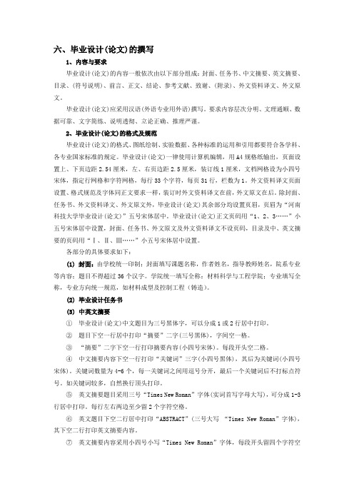
六、毕业设计(论文)的撰写1、内容与要求毕业设计(论文)的内容一般依次由以下部分组成:封面、任务书、中文摘要、英文摘要、目录、(符号说明)、前言、正文、结论、参考文献、致谢、(附录)、外文资料译文、外文原文。
毕业设计(论文)应采用汉语(外语专业用外语)撰写。
要求内容层次分明、文理通顺、数据可靠、文字简练、说明透彻、立论正确、推理严谨。
2、毕业设计(论文)的格式及规范毕业设计(论文)的格式、图纸绘制、实验数据、各种标准的运用和引用都要符合各学科、各专业国家标准的规定。
毕业设计(论文)一律使用计算机编辑,用A4规格纸输出,页面设置上、下页边距2.54厘米,左、右页边距2.5厘米,装订线1厘米,文档网格设为小四号宋体,指定行网格和字符网格,每行33个字符,每页31行,栏数为1。
外文资料译文页面设置、格式规范及字体同正文要求一样,装订时外文资料译文在前,外文原文在后。
除封面、任务书、外文资料译文、外文原文外,毕业设计(论文)其余部分均设置页眉,页眉为“河南科技大学毕业设计(论文)”五号宋体居中。
毕业设计(论文)正文页码用“1、2、3……”小五号宋体居中设置,封面、任务书、外文原文及外文资料译文不设页码,目录及中、英文摘要的页码用“Ⅰ、Ⅱ、Ⅲ……”小五号宋体居中设置。
各部分的具体要求如下:(1) 封面:由学校统一印制;封面填写课题名称,作者姓名,指导教师姓名,院系专业等内容;题目不得超过36个汉字。
学院统一填写全称:材料科学与工程学院;专业填写全称,专业方向统一规范,如材料成型及控制工程(铸造)。
(2) 毕业设计任务书(3) 中英文摘要①毕业设计(论文)中文题目为三号黑体字,可以分成1或2行居中打印。
②题目下空一行居中打印“摘要”二字(三号黑体),字间空一格。
③“摘要”二字下空一行打印摘要内容(小四号宋体)。
每段开头空二格。
④中文摘要内容下空一行打印“关键词”三字(小四号黑体),其后为关键词(小四号宋体)。
外文翻译排版格式参考

毕业设计(论文)外文资料翻译系别:电子信息系专业:通信工程班级:B100309姓名:张杨学号:B10030942外文出处:附件: 1. 原文; 2. 译文2014年03月An Introduction to the ARM 7 ArchitectureTrevor Martin CEng, MIEETechnical DirectorThis article gives an overview of the ARM 7 architecture and a description of its major features for a developer new to the device. Future articles will examine other aspects of the ARM architecture.Basic CharacteristicsThe principle feature of the ARM 7 microcontroller is that it is a register based load-and-store architecture with a number of operating modes. While the ARM7 is a 32 bit microcontroller, it is also capable of running a 16-bit instruction set, known as "THUMB". This helps it achieve a greater code density and enhanced power saving. While all of the register-to-register data processing instructions are single-cycle, other instructions such as data transfer instructions, are multi-cycle. To increase the performance of these instructions, the ARM 7 has a three-stage pipeline. Due to the inherent simplicity of the design and low gate count, ARM 7 is the industry leader in low-power processing on a watts per MIP basis. Finally, to assist the developer, the ARM core has a built-in JTAG debug port and on-chip "embedded ICE" that allows programs to be downloaded and fully debugged in-system.In order to keep the ARM 7 both simple and cost-effective, the code and data regions are accessed via a single data bus. Thus while the ARM 7 is capable of single-cycle execution of all data processing instructions, data transfer instructions may take several cycles since they will require at least two accesses onto the bus (one for the instruction one for the data). In order to improve performance, a three stage pipeline is used that allows multiple instructions to be processed simultaneously.The pipeline has three stages; FETCH, DECODE and EXECUTE. The hardware of each stage is designed to be independent so up to three instructions can be processed simultaneously. The pipeline is most effective in speeding up sequential code. However a branch instruction will cause the pipeline to be flushed marring its performance. As we shall see later the ARM 7 designers had some clever ideas to solve this problem.InstructionFig 1 ARM 3- Stage pipelineARM7 Programming ModelThe programmer's model of the ARM 7 consists of 15 user registers, as shown in Fig. 3, with R15 being used as the Program Counter (PC). Since the ARM 7 is a load-and- store architecture, an user program must load data from memory into the CPU registers, process this data and then store the result back into memory. Unlike other processors no memory to memory instructions are available.M1M2M34,R1,R2 (R4=R0+R2)3Fig 2 Load And Store ArchitectureAs stated above R15 is the Program Counter. R13 and R14 also have special functions; R13 is used as the stack pointer, though this has only been defined as a programming convention. Unusually the ARM instruction set does not have PUSH and POP instructions so stack handling is done via a set of instructions that allow loading and storing of multiple registers in a single operation. Thus it is possible to PUSH or POP the entire register set onto the stack in a single instruction. R14 has special significance and is called the "link register". When a call is made to a procedure, the return address is automatically placed into R14, rather than onto a stack, as might be expected. A return can then be implemented by moving the contents of R14 intoR15, the PC. For multiple calling trees, the contents of R14 (the link register) must be placed onto the stack.15 User registers +PCR13 is used as the stack pointer R14 is the link registerR14 is the Program Counter Current Program Status RegisterFig 3 User Mode Register ModelIn addition to the 16 CPU registers, there is a current program status register (CPSR). This contains a set of condition code flags in the upper four bits that record the result of a previous instruction, as shown in Fig 4. In addition to the condition code flags, the CPSR contains a number of user-configurable bits that can be used to change the processor mode, enter Thumb processing and enable/disable interrupts.31 30 29 28 27Negative Carry OverflowIRQ System UserUndefined instruction AbortThumb instruction setFig 4 Current Program Status Register and Flags Exception And Interrupt ModesThe ARM 7 architecture has a total of six different operating modes, as shown below. These modes are protected or exception modes which have associated interruptsources and their own register sets.User: This mode is used to run the application code. Once in user mode the CPSR cannot be written to and modes can only be changed when an exception is generated. FIQ: (Fast Interrupt reQuest) This supports high speed interrupt handling. Generally it is used for a single critical interrupt source in a systemIRQ: (Interrupt ReQuest) This supports all other interrupt sources in a system Supervisor: A "protected" mode for running system level code to access hardware or run OS calls. The ARM 7 enters this mode after resetAbort: If an instruction or data is fetched from an invalid memory region, an abort exception will be generatedUndefined Instruction:If a FETCHED opcode is not an ARM instruction, an undefined instruction exception will be generated.The User registers R0-R7 are common to all operating modes. However FIQ mode has its own R8 -R14 that replace the user registers when FIQ is entered. Similarly, each of the other modes have their own R13 and R14 so that each operating mode has its own unique Stack pointer and Link register. The CPSR is also common to all modes. However in each of the exception modes, an additional register一the saved program status register (SPSR),is added. When the processor changes the current value of the CPSR stored in the SPSR,this can be restored on exiting the exception mode.System&User FIQ Supervisor Abort IRQ Undefined Fig 5 Full Register Set For ARM 7Entry to the Exception modes is through the interrupt vector table. Exceptions in the ARM processor can be split into three distinct types.(i) Exceptions caused by executing an instruction, these include software interrupts, undefined instruction exceptions and memory abort exceptions(ii) Exceptions caused as a side effect of an instruction such as a abort caused by trying to fetch data from an invalid memory region.(iii) Exceptions unrelated to instruction execution, this includes reset, FIQ and IRQ interrupts.In each case entry into the exception mode uses the same mechanism. On generation of the exception, the processor switches to the privileged mode, the current value of the PC+4 is saved into the Link register (R14) of the privileged mode and the current value of CPSR is saved into the privileged mode's SPSR. The IRQ interrupts are also disabled and if the FIQ mode is entered, the FIQ interrupts are also disabled, Finally the Program Counter is forced to the exception vector address and processing of the exception can start. Usually the first action of the exception routine will be to pushPrefetch Abort(instruction fetch memory abort)Software interrupt (SWI)Undefined instruction ResetData Abort (data access momory abort)IRQ (interrupt)FIQ (fast interrupt)Supervisor Undefined Supervisor Abort Abort IRQ FIQ0x000000000x0000001C0x000000040x0000000C 0x000000080x000000100x00000018Fig 6 ARM 7 Vector TableA couple of things are worth noting on the vector table. Firstly, there is a missing vector at 0x000000014. This was used on an earlier ARM architecture and is left empty on ARM 7 to allow backward compatibility. Secondly, the FIQ interrupt is at the highest address so the FIQ routines could start from this address, removing the need for a jump instruction to reach the routine. It helps make entry into the FIQ routine as fast as possible.Once processing of the exception has finished, the processor can leave the privileged mode and return to the user mode. Firstly the contents of any registers previously saved onto the stack must be restored. Next the CSPR must be restored from the SPSR and finally the Program Counter is restored by moving the contents of the link register to R15, (i.e. the Program Counter). The interrupted program flow can then restart.Data TypesThe ARM instruction set supports six data types namely 8 bit signed and unsigned, 16 bit signed and unsigned plus 32 bit signed and unsigned. The ARM processor instruction set has been designed to support these data types in Little or Big-endian formats. However most ARM silicon implementations use the Little-endian format. ARM instructions typically have a three-operand format, as shown belowADD Rl,R2, R3 ; Rl=R2+R3ARM7 Program Flow ControlIn all processors there is a small group of instructions that are conditionally executed depending on a group of processor flags. These are branch instructions such as branch not equal. Within the ARM instruction set, all instructions are conditionally executable.31 28CONDFig. 7 Instruction Condition Code BitsThe top four bits of each instruction contain a condition code that must be satisfied if the instruction is to be executed. This goes a long way to eliminating small branches in the program code and eliminating stalls in the pipeline so increasing the overall program performance. Thus for small conditional branches of three instructions or less, conditional execution of instructions should be used. For larger jumps, normal branching instructions should be used.Fig. 8 Instruction Condition CodesThus our ADD instruction below could be prefixed with a condition code, as shown. This adds no overhead to instruction executionEQADD R1,R2,R3 ;If(Zero flag = 1)then R1 = R2+R3The ARM7 processor also has a 32-bit barrel shifter that allows it to shift or rotate one of the operands in a data processing instruction. This takes place in the same cycle as the instruction. The ADD instruction could be expanded as followsEQADD R1,R2 R3,LSL #2 ; If ( Zero flag = 1) then R1 = R2+ (R3 x 4) Finally the programmer may decide if a particular instruction can set the condition code flags in the CPSR.EQADDS R1,R2 R3,LSL #2; If (Zero flag = 1) then R1 = R2 + (R3 x4)and set condition code flagsIn the ARM instruction set there are no dedicated call or return instructions. Instead these functions are created out of a small group of branching instructions.The standard branch (B) instruction allows a jump of around+-32Mb. A conditional branch can be formed by use of the condition codes. For example, a "branch notequal" would be the branching instruction B and the condition code "NE" for not equal giving "BNE". The next form of the branch instruction is the branch with link. This is the branch instruction but the current value of the PC +4 is saved into R14, the link register. This acts as a CALL instruction by saving the return address into R14. A return instruction is not necessary since a return can be implemented by moving R14 into the PC. The return is more complicated in the case of an interrupt routine. Depending on the type of exception, it may be necessary to modify the contents of the link register to get the correct return address. For example, in the case of an IRQ or FIQ interrupt, the processor will finish its current instruction, increment the PC to the next instruction and then jumping to the vector table. This means that the value in the link register is PC+4 or one instruction ahead of the return address. This means we need to subtract 4 from the value in the link register to get the correct return address. This can be done in a single instruction thus: SUBS pc, r14, #4// PC=Link register-40x80000x400PC=0x80000x4000x8000Fig 9 Branch and Branch Link Instruction OperationBranching instructions are also used to enter the 16-bit Thumb instruction set. Both the branch and branch-with-link may perform an exchange between 32-bit and 16-bit instruction sets and vice versa .The Branch exchange will jump to a location and start to execute 16-bit Thumb instructions. Branch link exchange will jump to a location, save PC+4 into the link register and start execution of 16-bit Thumb instructions. In both cases, the T bit is set in the CPSR. An equivalent instruction is implemented in the Thumb instruction set to return to 32-bit ARM instruction processing.0x8000T=1Y=10x4000x4000x8000Fig. 10 Branch Exchange and Branch Link Exchange Instruction Operation Software InterruptsThe ARM instruction set has a software interrupt instruction. Execution of thisinstruction forces an exception as described above; the processor will enter supervisor mode and jump to the SWI vector at 0x00000008.Fig. 11 Software Interrupt InstructionThe bit field 0-23 of the SWI instruction is empty and can be used to hold an ordinal. On execution of an SWI instruction, this ordinal can be examined to determine which SWI procedure to run and gives over 16 million possible SWI functions.…Swi_ #1 . call swi function one…Tn the swi handlerregister unsigned*link ptr asm ("r14");// define a pointer to the hnk register Switch ((*(link-ptr-1))&Ox00FFFFFF) //calculate the number of the swi function{Case 0x01 : SWI_unction (); //Call the function…}This can be used to provide a hardware abstraction layer. In order to access OS calls or SFR registers, the user code must make a SWI call . All these functions are therunning in a supervisor mode, with a separate stack and link register.As well as instructions to transfer data to and from memory and to CPU registers, the ARM 7 has instructions to save and load multiple registers. It is possible to load or save all 16 CPU registers or a selection of registers in a single instruction. Needless tosay, this is extremely useful when entering or exiting a procedure.M0Fig. 12 Load and Store Multiple Instruction OperationThe CPSR and SPSR are only accessed by two special instructions to move their contents to and from a CPU register. No other instruction can act on them directly.MSRMRSR15R15Fig. 13 Programming The SPSR And CPSR RegistersTHUMB SupportThe ARM processor is capable of executing both 32-bit (ARM) instructions and 16- Bit (Thumb instructions). The Thumb instruction set must always be entered byrunning a Branch exchange or branch link exchange instruction and NOT by setting the T bit in the CPSR. Thumb instructions are essentially a mapping of their 32 bit cousins but unlike the ARM instructions, they are unconditionally executed except though for branch instructions.Fig. 14 Thumb Instruction ProcessingThumb instructions reduced number of only have unlimited access to registers RO-R7 and R13一Rl5. A instructions can access the full register set.Fig.15 Thumb programmers modelThe Thumb instruction set has the same load and store multiple instructions as ARM and in addition, has a modified version of these instructions in the form of PUSH and POP that implement a full descending stack in the conventional manner. The Thumb instruction set also supports the SWI instruction, except that the ordinal field is only 8 bits long to support 256 different SWI calls. When the processor is executing Thumb code and an exception occurs, it will switch to ARM mode in order to process the exception. When the CPSR is restored the, Thumb bit will be reset and the processor continues to run Thumb instructions.BCXBXFig.16 Thumb Exception ProcessingThumb has a much higher code density than ARM code, needing some 70% of the space of the latter. However in a 32-bit memory, ARM code is some 40% faster than Thumb. However it should be noted that if you only have 16-bit wide memory then Thumb code will be faster than ARM code by about 45%. Finally the other important aspect of Thumb is that it can use up to 30% less power than ARM code.ARM7的体系结构介绍特里沃马丁曾,鼠技术总监本文给出了ARM 7架构的概述和开发新的设备,以及主要功能的描述,未来将研究ARM体系结构的其他方面。
外文文献翻译——参考格式

广东工业大学华立学院本科毕业设计(论文)外文参考文献译文及原文系部经济学部专业经济学年级 2007级班级名称 07经济学6班学号 16020706001学生姓名张瑜琴指导教师陈锶2011 年05月目录1挑战:小额贷款中的进入和商业银行的长期承诺 (1)2什么商业银行带给小额贷款和什么把他们留在外 (2)3 商业银行的四个模型进入小额贷款之内 (4)3.1内在的单位 (4)3.2财务子公司 (5)3.3策略的同盟 (5)3.4服务公司模型 (6)4 合法的形式和操作的结构比较 (8)5 服务的个案研究公司模型:厄瓜多尔和Haiti5 (9)1 挑战:小额贷款中的进入和商业银行的长期承诺商业银行已经是逐渐重要的运动员在拉丁美洲中的小额贷款服务的发展2到小额贷款市场是小额贷款的好消息客户因为银行能提供他们一完整类型的财务的服务,包括信用,储蓄和以费用为基础的服务。
整体而言,它也对小额贷款重要,因为与他们广泛的身体、财务的和人类。
如果商业银行变成重的运动员在小额贷款,他们能提供非常强烈的竞争到传统的小额贷款机构。
资源,银行能廉宜地发射而且扩张小额贷款服务rela tively。
如果商业广告银行在小额贷款中成为严重的运动员,他们能提出非常强烈的竞争给传统的小额贷款机构。
然而,小额贷款社区里面有知觉哪一商业银行进入进入小额贷款将会是短命或浅的。
举例来说,有知觉哪一商业银行首先可能不搬进小额贷款因为时候建立小额贷款操作到一个有利润的水平超过银行的标准投资时间地平线。
或,在进入小额贷款,银行之后可能移动在-上面藉由增加贷款数量销售取利润最大值-或者更坏的事,退出如果他们是不满意与小额贷款的收益性的水平。
这些知觉已经被特性加燃料商业银行的情形进入小额贷款和后来的出口之内。
在最极端的,一些开业者已经甚至宣布,”降低尺度死!”而且抛弃了与主意合作的商业银行。
在最 signific 看得到的地方,蚂蚁利益商业银行可能带给小额贷款,国际的ACCION 发展发射而且扩张的和一些商业银行的关系小额贷款操作。
超详细外文翻译模板及写法
XX学院毕业论文(设计)外文翻译撰写格式规范一、外文翻译形式要求1、要求本科生毕业论文(设计)外文翻译部分的外文字符不少于1.5万字, 每篇外文文献翻译的中文字数要求达到2000字以上,一般以2000~3000字左右为宜。
2、翻译的外文文献应主要选自学术期刊、学术会议的文章、有关著作及其他相关材料,应与毕业论文(设计)主题相关,并作为外文参考文献列入毕业论文(设计)的参考文献。
3、外文翻译应包括外文文献原文和译文,译文要符合外文格式规范和翻译习惯。
二、打印格式XX学院毕业论文(设计)外文翻译打印纸张统一用A4复印纸,页面设置:上:2.8;下:2.6;左:3.0;右:2.6;页眉:1.5;页脚:1.75。
段落格式为:1.5倍行距,段前、段后均为0磅。
页脚设置为:插入页码,居中。
具体格式见下页温馨提示:正式提交“XX学院毕业论文(设计)外文翻译”时请删除本文本中说明性的文字部分(红字部分)。
XX学院毕业论文(设计)外文翻译题目:系别:服装与艺术设计系专业:班级:学号:学生姓名:一、外文原文见附件(文件名:12位学号+学生姓名+3外文原文.文件扩展名)。
二、翻译文章翻译文章题目(黑体小三号,1.5倍行距,居中)作者(用原文,不需翻译,Times New Roman五号,加粗,1.5倍行距,居中)工作单位(用原文,不需翻译,Times New Roman五号,1.5倍行距,居中)摘要:由于消费者的需求和汽车市场竞争力的提高,汽车检测标准越来越高。
现在车辆生产必须长于之前的时间并允许更高的价格进行连续转售……。
(内容采用宋体五号,1.5倍行距)关键词:汽车产业纺织品,测试,控制,标准,材料的耐用性1 导言(一级标题,黑体五号,1.5倍行距,顶格)缩进两个字符,文本主体内容采用宋体(五号),1.5倍行距参考文献(一级标题,黑体五号, 1.5倍行距,顶格)略(参考文献不需翻译,可省略)资料来源:AUTEX Research Journal, Vol. 5, No3, September 2008*****译****校(另起一页)三、指导教师评语***同学是否能按时完成外文翻译工作。
外文参考文献及翻译稿的要求与格式
百度文库- 让每个人平等地提升自我!外文参考文献及翻译稿的要求及格式一、外文参考文献的要求1、外文原稿应与本研究项目接近或相关联;2、外文原稿可选择相关文章或节选章节,正文字数不少于1500字。
3、格式:外文文献左上角标注“外文参考资料”字样,小四宋体。
1.5倍行距。
标题:三号,Times New Roman字体加粗,居中,行距1.5倍。
段前段后空一行。
作者(居中)及正文:小四号,Times New Roman字体,首行空2字符。
4、A4纸统一打印。
二、中文翻译稿1、中文翻译稿要与外文文献匹配,翻译要正确;2、中文翻译稿另起一页;3、格式:左上角标“中文译文”,小四宋体。
标题:宋体三号加粗居中,行距1.5倍。
段前、段后空一行。
作者(居中)及正文:小四号宋体,数字等Times New Roman字体,1.5倍行距,首行空2字符。
正文字数1500左右。
4、A4纸统一打印。
格式范例如后所示。
百度文库 - 让每个人平等地提升自我!外文参考文献Implementation of internal controls of small andmedium-sized pow erStephen Ryan The enterprise internal control carries out the strength to refer to the enterprise internal control system execution ability and dynamics, it is the one whole set behavior and the technical system, is unique competitive advantage which the enterprise has; Is a series of …………………………标题:三号,Times New Roman字体加粗,居中,行距1.5倍。
外文翻译格式
外文翻译格式
外语翻译通常需要遵循一定的格式,以确保翻译内容的准确性和易读性。
以下是一个700字外文翻译的通用格式示例:
1. 标题:翻译的内容的标题,通常与原文标题保持一致,居中显示。
2. 原文:原文内容,可将原文段落编号,并保留原文格式,如段落缩进或列表。
3. 译文:相关段落的翻译内容,与原文一一对应,并保持相同的段落编号和格式。
4. 术语翻译:将翻译中使用的特定术语或固定表达进行解释和翻译,避免出现歧义。
5. 校对与审校:对翻译内容进行校对和审校,确保翻译准确无误。
6. 结论:对整个翻译内容进行总结和评价,提出自己的观点和见解。
7. 参考文献:如有需要,列出翻译过程中所参考的文献或资料。
8. 附录:如有需要,可在翻译后添加附录,补充相关资料或说明。
注意事项:
- 翻译应遵循专业的术语和语法规范,尽量保持翻译内容的准确性。
- 可根据需要调整段落的分配和序号,以符合原文和翻译内容的逻辑结构。
- 保持翻译格式的统一和美观,使用合适的字体和字号,并注意标点符号的使用。
- 翻译结束后,应进行校对和审校,以确保翻译质量的准确性和流畅性。
总之,一个700字外文翻译的格式应该清晰明了,结构合理,准确无误,并能为读者提供一个清晰且易于理解的翻译内容。
外文翻译撰写规范
第一部分:格式篇
1.外文翻译封面中从“院系”——“指导老师”旁边的下划线请保持长度一致。
2.封面中“原文出处”信息应该完整,同参考文献中的外文文献格式。
3.先中文后英文,中文页码为阿拉伯数字,英文页码为罗马数字。
4.中英文上方第一行都是文章或者书的名称,第二行是出处。
5.字间距为标准,行距为固定值,设置值为23。
如标题与标题、标题与段落之
间间距明显较大时,请选定标题并选择“段落”检查间距中“段前”、“段后”
是否是0行。
6.中文文章段落中出现除序号外的阿拉伯数字或英文应用Times New Roman字
体。
第二部分:内容篇
1.必须是英文文献翻译成中文,不能中文翻译成英文。
2. 英文文献必须是外国人写的,不能只是中国人发表的外文论文。
3.外文文献只要和所写课题相关即可,不用完全一致。
如课题为审计风险,如果找不到审计风险的外文,也可以找审计相关的外文即可。
4.关键词前后翻译必须一致,英文缩写在中文翻译中第一次出现时必须翻译出全称。
5.不能仅仅依靠翻译软件,翻译的中文应检查是否语句通顺,是否有词不达意的情况。
- 1、下载文档前请自行甄别文档内容的完整性,平台不提供额外的编辑、内容补充、找答案等附加服务。
- 2、"仅部分预览"的文档,不可在线预览部分如存在完整性等问题,可反馈申请退款(可完整预览的文档不适用该条件!)。
- 3、如文档侵犯您的权益,请联系客服反馈,我们会尽快为您处理(人工客服工作时间:9:00-18:30)。
外文翻译院系安全工程学院专业消防工程班级04050202学号2010040502041 姓名指导教师负责教师沈阳航空航天大学2013年6月氧气消耗流量计测定装修家具组件或合成材料及床垫的热和可见热释放速率的方法第一章管理1.1范围1.1.1本文是使用氧气消耗流量计测定装修家具组件或合成材料及床垫的热和可见热释放速率的方法。
1.1.2在本文的方法中,使用的是水平放置的样本,样本用外部点火器点燃来经受热辐射。
1.1.3辐射曝量应该维持在35 kW/m2的恒定速率下来确定维持燃烧的时间,每一单位面积的热辐射释放速率和有效的燃烧热(MJ/kg).1.1.4热量释放速率是通过氧浓度的测定决定的耗氧量和燃烧物品的质量损失来确定的。
1.1.5燃烧的有效热量应该取决于与热量释放速率相结合的样品损失速率。
1.1.6试验应该使用长凳大小规模的家具或者覆盖软垫组织和填料的材料,但是不包括框架结构。
1.1.7安全1.1.7.1这个标准不是用来解决所有与设备相关的安全问题。
1.1.7.2在使用该标准之前通过设立适当安全卫生实践来决定监管限制的可实用性应当是使用该标准人的责任义务。
1.2目的1.2.1本文方法是根据与燃烧需氧量直接相关的净燃烧热的观察基础下完成的。
消耗1kg氧气的时候大约释放13.1 × 10³ kJ的热量。
1.2.2实验中的样品应该在外部加热量为35 kW/m2的环境空气下进行燃烧。
1.2.3热量释放速率是通过氧浓度的测定决定的耗氧量和燃烧物品的质量损失来确定的。
1.2.4主要的测量值是氧浓度和排烟速率,数值用来(同时包括温度和压力测量值)评价热释放速率。
1.2.4.1额外的测量包括质量损失速率,维持燃烧的时间,有效的燃烧热,比消光面积和其他相关材料或者性能标准要求的方法。
1.2.4.2可燃烧性能应该由初始燃烧到维持燃烧的时间来决定。
1.3应用1.3.1本文的方法用来确定燃烧特性,包括放置在规定的热燃烧通量下的材料和复合材料的点燃时间和热释放速率(在1.2.4.1中提到)。
1.3.2定量热释放测量给家居装饰用品业的设计、床垫产品和产品发展提供潜在的资料。
1.4试验的限制本文数据在以下的条件下适用:(1)爆裂发生的时候(2)在点火前试样充分膨胀以致触碰到火花塞或者在燃烧时材料膨胀触碰到加热器平盘。
1.5单位和公式。
1.5.1国际标准单位。
文中的米制单位与国际单位制一致(SI)。
1.5.2除非有特别声明,所有的尺寸包括文中的数字应该与标称的误差不超过1mm。
1.5.3符号表。
文中用到以下符号:As=标称样本暴露面积(0.01m2)C=耗氧量分析的校准常数(m1/2 kg1/2 K1/2)△Hc/ro=净燃烧热(kJ/kg)△Hc,eff=有效燃烧热(kJ/kg)I=实际光束强度I0=无烟光束强度k=烟消光系数(m -1)L=梁消光路径长度(m )m=样品质量(kg)m f =最终样品质量(kg )m i =初始样品质量(kg)m=样品质量损失速率(kg/sec )△P=孔板流量计压差(Pa )q''=总热量释放(kJ/m 2)q˙=热量释放率(kW )q˙ ''=每单位面积热释放速率(kW/m 2)t 0=氧化学计量/燃料质量比t=时间(sec )t d =氧分析仪延迟时间 (sec)△t= 取样间隔时间 (sec)Te =气体在孔板流量计的绝对温度(K)v = 在激光光度计位置处的排气流量速率(m 3/sec)X O 2 =氧分析读出的O 2摩尔分数 20O X = 氧气分析仪的初始读数21O X = 在延迟时间校正前的氧分析仪读数f =平均特定烟消光面积(m 2/kg)第二章引用的出版物2.1总体。
在这章中列出的文件或其中的部分参考于此标准并且应该被认为是此文件的一部分。
2.2美国国家防火协会出版。
美国消防协会,Batterymarch Park ,P.O. Box 9101, Quincy, MA 02269-9101.NFPA 271,利用氧消耗热量计测量出的材料和产品的热量和可视烟的释放速率标准。
2.3其他出版物。
(保留)第三章定义3.1总体。
在此章包含的定义应该适用于此标准的条款。
如果条款中没有,应以通常用法为准。
3.2 NFPA官方定义。
3.2.1应改做的准备工作。
指定一个强制性的要求。
3.2.2应该做的准备工作。
指定一个推荐或者是个没被要求的建议。
3.2.3标准。
文中的主要部分只有强制规定才用“应该”这个词语来指明要求,并且通常适用于另一个规定或者法律规定、注脚,或者印刷良好的标注,并且不被认为是一个标准的一部分。
3.3一般定义。
3.3.1燃烧热3.3.1.1有效燃烧热。
测量到的热量释放被分为在指定时间的质量损失。
3.1.1.2净燃烧热。
氧弹量热器测量燃烧热,校正气态水的产生。
3.3.2热释放速率。
由样本产生的热量,单位时间。
3.3.3热流密度。
在实验开始时由加热器外部强加在试样上的热辐射。
3.3.4可燃性。
燃烧的倾向,由维持燃烧的时间确定,以秒计,在指定的加热通量条件下。
3.3.5定向。
在实验期间试样的外露面(例如,水平对着加热器)。
3.3.6氧消耗原理。
燃烧期间消耗氧的质量和热量释放之间的关联。
3.3.7烟气灰暗度。
由光衰减度衡量的烟气导致光通量减弱度。
3.3.8持续燃烧。
在试样有火焰产生或者表面产生火焰的时间持续最少4秒。
3.3.9可见烟雾。
在实验中由燃烧的产品产生的阻碍光线传输的烟雾。
第四章实验仪器4.1总述。
4.1.1实验仪器由以下几部分组成:(1)一个圆锥形的电加热器。
(2)样品夹。
(3)一个废气放排体统,包含氧气监视和流动的功能的仪器。
(4)一个点火火花塞。
(5)数据采集和分析系统。
(6)测量试样损失的重量传感器。
4.1.2仪器组成见图4.1.2。
图4.1.2 仪器组成4.2特别的。
试验装置应与NFPA271(使用氧气消耗流量计测定装修家具组件或合成材料及床垫的热和可见热释放速率试验标准方法)中的第四章要求相符合。
4.3标度。
仪器应按照NFPA的第五章校准(使用氧气消耗流量计测定装修家具组件或合成材料及床垫的热和可见热释放速率试验标准方法)。
第五章试样5.1试样。
样品试样应该按照5.2.A方案或者5.3.B方案准备。
5.2方案A。
方案A所使用的仪器和设备应该按照5.2.1至5.2.11条来准备。
5.2.1切割设备。
泡沫应该用锯条切割。
(A)需要用到泡沫切割片。
(B)这个刀片应该没有刀齿并且应该在边缘处有像扇贝波浪的形状。
(C)刀片必须锋利。
(D)不能使用聚硅酮或者其他油类来润滑刀片。
(E)润滑工作应该单独使用石墨或者钼涂擦。
(F)锯条应该能对泡沫进行垂直切割。
(G)叶片导应该设置的比要切割的物品高出12mm以内。
5.2.2成型块。
成型块应该被制作成98 mm × 98 mm × 50 mm的规格。
(A)每个规模误差控制在0.5mm以内。
(B)紧密木材应该用来当做成型块的材料。
(C)只由完全在窖内烘干的木材才能被用作制作成型块的材料。
(D)所有表面应该被整齐切割并且应该光滑。
(E)边缘不应该是圆的,但是拐角处应该是略圆的。
(F)木块应该允许用丙烯酸涂漆以保证坚实、光滑、牢固的表面。
(G)至少应有12块木材,以便若干样本在同一时间准备。
5.2.3粘合剂。
阻燃剂应该可燃性较低。
5.2.3.1粘合剂应该有爪力来保证弹性垫片的插入物并且在实验之前不变形。
5.2.3.2为了可燃性测试的程序,织物的黏着部分既不能火焰过度也不能延迟燃烧。
5.2.4粘着剂应用。
粘着剂应用的方案应该与特殊粘着剂选择相符。
5.2.5粘合剂检查。
5.2.5.1 为了检验粘合剂的有效性,应将一小部分的粘合剂放在两小块织物或者衬里上。
5.2.5.2粘合剂应该被允许晾干至少12小时并且之后试着使织物片分开。
5.2.5.3如果粘合剂是合格的,被粘合起来的织物片不应该在织物片被撕开前分开。
5.2.6胶带。
有粘合剂的护条或者其他胶带应该被允许用来辅助安装实验组件。
5.2.7铝箔。
需要用到0.03mm到0.04mm厚的铝箔。
5.2.8样本的基本准备。
样本的基本准备详情见5.2.8.1和5.2.8.2.5.2.8.1这些基本指令应该适合只由单层组成的织物和单层弹性垫片组成的样本。
(A)同样的指令应该适用于衬里贴在织物背面的样本。
(B)在5.2.8.1(A)中提到的样本,织物/衬里混合物应该被单独看做是织物。
(C)对于用多重填充层、单独衬里层和其他特殊结构,补充说明在5.2.11中给出。
5.2.8.2 弹性填料块的切割。
(A)每个弹性填料块应该被切割成正方形,90°角,尺寸为(102mm±0.5mm)× (102.5 mm ± 0.5 mm)。
(B)当复合材料的填充材料只是单独的弹性填料时弹性填料块的厚度应为50mm。
5.2.8.3 弹性填充材料的形成。
每一批弹性垫片样本应该按照质量检查。
(A)每一种类型的样本应该进行至少三次实验。
(B)一旦三个弹性垫片被切割,质量应该被确定下来。
(C)不能有木块超过三个质量平均值得105%也不能低于95%(D)如果误差出现了,应该切割多一些的木块,并且确定质量。
(E)复合材料直到三个木块的弹性垫片符合5.2.8.3(C)中描述的误差的5%后才能被准备。
(F)符合条件的木块应该被标记以便于追踪。
(G)每个木块的弹性垫片的质量应该和木块的识别标记一起被记录下来。