自动五速手动变速箱- EASYTRONIC 3.0外文文献翻译、中英文翻译
变速器论文中英文对照资料外文翻译文献

中英文对照外文翻译汽车变速器设计我们知道,汽车发动机在一定的转速下能够达到最好的状态,此时发出的功率比较大,燃油经济性也比较好。
因此,我们希望发动机总是在最好的状态下工作。
但是,汽车在使用的时候需要有不同的速度,这样就产生了矛盾。
这个矛盾要通过变速器来解决。
汽车变速器的作用用一句话概括,就叫做变速变扭,即增速减扭或减速增扭。
为什么减速可以增扭,而增速又要减扭呢?设发动机输出的功率不变,功率可以表示为 N = w T,其中w是转动的角速度,T 是扭距。
当N固定的时候,w与T是成反比的。
所以增速必减扭,减速必增扭。
汽车变速器齿轮传动就根据变速变扭的原理,分成各个档位对应不同的传动比,以适应不同的运行状况。
一般的手动变速器内设置输入轴、中间轴和输出轴,又称三轴式,另外还有倒档轴。
三轴式是变速器的主体结构,输入轴的转速也就是发动机的转速,输出轴转速则是中间轴与输出轴之间不同齿轮啮合所产生的转速。
不同的齿轮啮合就有不同的传动比,也就有了不同的转速。
例如郑州日产ZN6481W2G型SUV车手动变速器,它的传动比分别是:1档3.704:1;2档2.202:1;3档1.414:1;4档1:1;5档(超速档)0.802:1。
当汽车启动司机选择1档时,拨叉将1/2档同步器向后接合1档齿轮并将它锁定输出轴上,动力经输入轴、中间轴和输出轴上的1档齿轮,1档齿轮带动输出轴,输出轴将动力传递到传动轴上(红色箭头)。
典型1档变速齿轮传动比是3:1,也就是说输入轴转3圈,输出轴转1圈。
当汽车增速司机选择2档时,拨叉将1/2档同步器与1档分离后接合2档齿轮并锁定输出轴上,动力传递路线相似,所不同的是输出轴上的1档齿轮换成2档齿轮带动输出轴。
典型2档变速齿轮传动比是2.2:1,输入轴转2.2圈,输出轴转1圈,比1档转速增加,扭矩降低。
当汽车加油增速司机选择3档时,拨叉使1/2档同步器回到空档位置,又使3/4档同步器移动直至将3档齿轮锁定在输出轴上,使动力可以从轴入轴—中间轴—输出轴上的3档变速齿轮,通过3档变速齿轮带动输出轴。
自动变速器英文文献翻译之欧阳化创编
毕业设计外文翻译THE RESEARCHS OFAMT SHIFTING SCHEDULESThe modern automatic transmission is by far,the most complicated mechanical component in today`s automobile.It is a type of transmission that sifts itself.A fluid coupling or torque converter is used instead of a manually operated clutch to connect the transmission to the engine.There are two basic types of automatic transmission based on whether the vehicle is rear wheel drive or front wheel drive.On a rear wheel drive car,the transmission is usually mounted to the back of the engine and is located under the hump in the center of the floorboard alongside the gas pedal position.A drive shaft connects the transmission to the final drive which is located in the rear axle and is used to send power to the rear wheels.Power flow on this system is simple and straight forward going from the engine,through the torque converter,then trough the transmission and drive shaft until it reaches the final drive where it is split and sent to the two rear transmission.On a front wheel drive car,the transmission is usually combined with the final drive to form what is called a transaxle.The engine on a front wheel drive car is usually mounted sideways in the car with the transaxle tucked under it on the side of the engine facing the rear of the car.Frontaxles are connected directly to the transaxle and provide power to front wheels.In this example,power floes from the engine,through the torque converter to a larger chain that sends the power through a 180 degree turn to the transmission that is along side the engine.From there,the power is routed through the transmission to the final drive where it is split and sent to the two front wheels through the drive axles.There are a number of other arrangements including front drive vehicles where the engine is mounted front to back instead of sideways and there are other systems that drive all four wheels but the two systems described here are by far the most popular.A much less popular rear and is connected by a drive shaft to the torque converter which is still mounted on the engine.This system is found on the new Corvette and is used in order to balance the weight evenly between the front and rear wheels for improved performance and handling.Another rear drive system mounts everything,the engine,transmission and final drive in the rear.This rear engine arrangement is popular on the Porsche。
自动变速器英文文献翻译

毕业设计外文翻译THE RESEARCHS OFAMT SHIFTING SCHEDULESThe modern automatic transmission is by far,the most complicated mechanical component in today`s automobile. It is a type of transmission that sifts itself.A fluid coupling or torque converter is used instead of a manually operated clutch to connect the transmission to the engine.There are two basic types of automatic transmission based on whether the vehicle is rear wheel drive or front wheel drive. On a rear wheel drive car,the transmission is usually mounted to the back of the engine and is located under the hump in the center of the floorboard alongside the gas pedal position. A drive shaft connects the transmission to the final drive which is located in the rear axle and is used to send power to the rear wheels. Power flow on this system is simple and straight forward going from the engine,through the torque converter,then trough the transmission and drive shaft until it reaches the final drive where it is split and sent to the two rear transmission.On a front wheel drive car,the transmission is usually combined with the final drive to form what is called a transaxle. The engine on a front wheel drive car is usually mounted sideways in the car with the transaxle tucked under it on the side of the engine facing the rear of the car. Front axles are connected directly to the transaxle and provide power to front wheels. In this example,power floes from the engine,through the torque converter to a larger chain that sends the power through a 180 degree turn to the transmission that is along side the engine. From there,the power is routed through the transmission to the final drive where it is split and sent to the two front wheels throughthe drive axles.There are a number of other arrangements including front drive vehicles where the engine is mounted front to back instead of sideways and there are other systems that drive all four wheels but the two systems described here are by far the most popular. A much less popular rear and is connected by a drive shaft to the torque converter which is still mounted on the engine. This system is found on the new Corvette and is used in order to balance the weight evenly between the front and rear wheels for improved performance and handling. Another rear drive system mounts everything,the engine,transmission and final drive in the rear. This rear engine arrangement is popular on the Porsche;The modern automatic transmission consists of many components and systems that designed to work together in a symphony of planetary gear sets,the hydraulic system, seals and gaskets,the torque converter,the governor and the modulator or throttle cable and computer controls that has evolved over the years into what many mechanical inclined individuals consider to be an art from. Here try to used simple,generic explanation where possible to describe these systems.1Planetary gear setsAutomatic transmission contain many gears in various combinations. In a manual transmission,gears slide along shafts as you move the shift lever from one position to another,engaging various sizes gears as required in order to provide the correct gear ratio. In an automatic transmission,how ever,the gears are never physically moved and are always engaged to the same gears. This is accomplished through the use of planetary gear sets.The basic planetary gear set consists of a sun gear,a ring and two or more planet gears,all remaining in constant mesh. The planet gears are connected to each other through a common carrier which allows the gears to spin on shafts called “pinions” which are attached to the carrier.One example of a way that this system can be used is by connecting the ring gear to the input shaft coming from the engine,connecting the planet carrier to the output shaft,and locking the sun gear so that it can`t move. In this scenario,when we turn the ring gear,the planets will “walk” along the sun gearwhich is held stationary causing the planet carrier to turn the output shaftin the same direction as the input shaft but at a slower speed causing gearreduction similar to a car in first gear .If we unlock the sun gear and lock any two elements together,this will causeall three elements to turn at the same speed so that to output shaft will turnat the same rate of speed as the input shaft. This is like a car that is thirdor high gear. Another way we can use a planetary gear set is by locking the planetcarrier from moving,then applying power to the ring gear which will cause thesun gear to turn in opposite direction giving us reverse gear.The illustration in Figure shows how the simple system described above wouldlook in an actual transmission. The input shaft is connected to the ring gear,theoutput shaft is connected to the planet carrier which is also connected to a“Multi-disk” clutch pack. The sun gear is connected to drum which is also connected to the other half of the clutch pack. Surrounding the outside of thedrum is a band that can be tightened around the drum when required to preventthe drum with the attached sun gear from turning.The clutch pack is used,in this instance,to lock the planet carrier with thesun gear forcing both to turn at the same speed. If both the clutch pack andthe band were released,the system would be in neutral. Turning the input shaftwould turn the planet gears against the sun gear,but since noting is holdingthe sun gear,it will just spin free and have no effect on the output shaft. Toplace the unit in first gear,the band is applied to hold the sun gear from moving.To shift from first to high gear,the band is released and the clutch is appliedcausing the output shaft to turn at the same speed as the input shaft.Many more combinations are possible using two or more planetary sets connected in various way to provide the different forward speeds and reversethat are found in modern automatic transmission.2Clutch packA clutch pack consists of alternating disks that fit inside a clutch drum.Half of the disks are steel and have splines that fit into groves on the insideof the drum. The other half have a friction material bonded to their surfaceand have splines on the inside edge that fit groves on the outer surface of the adjoining hub. There is a piston inside the drum that is activated by oil pressure at the appropriate time to squeeze the clutch pack together so that the two components become locked and turn as one.3One-way ClutchA one-way clutch also known as a “sprag” clutch is a device that will allow a component such as ring gear to turn freely in one direction but not in the other. This effect is just like that bicycle,where the pedals will turn the wheel when pedaling forward,but will spin free when pedaling backward.A common place where a one-way clutch is used is in first gear when the shifter is in the drive position. When you begin to accelerate from a stop,the transmission starts out in first gear. But have you ever noticed what happens if you release the gas while it is still in first gearThe vehicle continues to coast as if you were in neutral. Now,shift into Low gear instead of Drive. When you let go of the gas in this case,you will feel the engine slow you down just like a standard shift car. The reason for this is that in Drive,one-way clutch is used whereas in Low,a clutch pack or a band is used.4Torque ConverterOn automatic transmission,the torque converter takes the place of the clutch found on standard shift vehicles. It is there to allow the engine to continue running when the vehicle comes to a stop. The principle behind a torque converter is like taking a fan that is plugged into the wall and blowing air into another fan which is unplugged. If you grab the blade on the unplugged fan,you are able to hold it from turning but as soon as you let go,it will begin to speed up until it comes close to speed of the powered fan. The difference with a torque converter is that instead of using air it used oil or transmission fluid,to be more precise.A torque converter is a lager doughnut shaped device that is mounted between the engine and the transmission. It consists of three internal elements that work together to transmit power to the transmission. The three elements of the torque converter are the pump,the Turbine,and the Stator. The pump is mounteddirectly to the torque housing which in turn is bolted directly to the engine’s crankshaft and turns at engine speed. The turbine is inside the housing and is connected directly to the input shaft of the transmission providing power to move the vehicle. The stator is mounted to a one-way clutch so that it can spin freely in one direction but not in the other. Each of the three elements has fins mounted in them to precisely direct the flow of oil through the converter.With the engine running,transmission fluid is pulled into the pump section and is pushed outward by centrifugal force until it reaches the turbine section which stars it running. The fluid continues in a circular motion back towards the center of the turbine where it enters the stator. If the turbine is moving considerably slower than the pump,the fluid will make contact with the front of the stator fins which push the stator into the one way clutch and prevent it from turning. With the stator stopped,the fluid is directed by the stator fins to re-enter the pump at a “help” angle providing a torque increase. As the speed of the turbine catches up with the pump,the fluid starts hitting the stator blades on the back-side causing the stator to turn in the same direction as the pump and turbine. As the speed increase,all three elements begin to turn at approximately the same speed. Sine the ‘80s,in order to improve fuel economy,torque converters have been equipped with a lockup clutch which locks the turbine to the pump as the vehicle reaches approximately 40-50 mph. This lockup is controlled by computer and usually won’t engage unless the transmission is in 3rd or 4th gear.5Hydraulic SystemThe hydraulic system is a complex maze of passage and tubes that sends that sends transmission fluid and under pressure to all parts of the transmission and torque converter and. Transmission fluid serves a number of purpose including : shift control ,general lubrication and transmission cooling;Unlike the engine ,which uses oil primary for lubrication ,every aspect of a transmission ‘s function is dependant on a constant supply of fluid is send pressure. In order to keep the transmission at normal operating temperature,aportion of the fluid is send to through one of two steel tubes to a special chamber that is submerged in anti-freeze in the radiator. Fluid passing through this chamber is cooled and then returned to the transmission through the other steel tube. A typical transmission has an avenge of ten quarts of fluid between the transmission,torque converter,and cooler tank,In fact,most of the components of a transmission are constantly submerged in fluid including the clutch packs and bands. The friction surfaces on these parts are designed to operate properly only when they are submerged in oil.6Oil PumpThe transmission oil pump not to confused with the pump element inside the torque converter is responsible for producing all the oil pressure that is required in the transmission. The oil pump is mounted to front of the transmission case and is directly connected to a flange on the engine crankshaft,the pump will produce pressure whenever the engine is running as there is a sufficient amount of transmission fluid available. The oil enters the pump through a filter that is located at bottom of the transmission oil pan and travels up a pickup tube directly to the oil pump. The oil is then sent,under pressure to the pressure regulator,the valve body and the rest of the components,as required.7Valve BodyThe valve body is the control center of the automatic transmission. It contains a maze of channels and passages that direct hydraulic fluid to the numerous valves which when activate the appropriate clutch pack of band servo to smoothly shift to the appropriate gear for each driving situation. Each of the many valves in the valve body has a specific purpose and is named for that function. For example the 2-3 shift valve activates the 2nd gear up-shift or the 3-2 shift timing valve which determines when a downshift should occur.The most important valve and the one that you have direct control over is the manual valve. The manual valve is directly connected to the gear shift handle and covers and uncovers various passages depending on what position the gear shift is paced in. When you place the gear shift in Drive,for instance,the manual valve directs fluid to the clutch pack s that activates 1st gear. Italso sets up to monitor vehicle speed and throttle position so that it can determine the optimal time and the force for the 1-2 shift. On computer controlled transmission,you will also have electrical solenoids that are mounted in the valve body to direct fluid to the appropriate clutch packs or bands under computer control to more precisely control shift points.8Seals and GasketsAn automatic transmission has many seals and gaskets to control the flow of hydraulic fluid and to keep it from leaking out. There are two main external seals : the front seal and the rear seal. The front seal seals the point where the torque converter mounts to the transmission case. This seal allows fluid to freely move from the converter to the transmission but keeps the fluid from leaking out. The rear seal keeps fluid from leaking past the output shaft.A seal is usually made of rubber similar to the rubber in a windshield wiper blade and is used to keep oil from leaking past a moving part such as a spinning shaft. In some cases,the rubber is assisted by a spring that holds he rubber in close contact with the spinning shaft.A gasket is a type of seal used to seal two stationary parts that are fasted together. Some common gasket materials are : paper,cork,rubber,silicone and soft metal.Aside from the main seals,there are also a number of other seals and gasket that vary from transmission to transmission. A common example is the rubber O-ring that seals the shaft for the shift control lever. This is the shaft that you move when you manipulate the gear shifter. Another example that is common to most transmission is the oil pan gasket. In fact,seals are required anywhere that a device needs to pass through the transmission case with each one being a potential source for leaks.9Computer ControlsThe computer uses sensors on the engine and transmission to detect such things as throttle position,vehicle speed,engine speed,engine load,stop light switch position,etc. to control exact shift points as well as how soft or firm the shift should be. Some computerized transmission even learn your driving style andconstantly adapt to it so that every shift is timed precisely when you would need it.Because of computer controls,sports models are coming out with the ability to take manual control of the transmission as through it were a stick shift lever through a special gate,then tapping it in one direction or the other in order to up-shift at will. The computer monitors this activity to make sure that the driver dose not select a gear that could over speed the engine and damage it.Another advantage to these “ smart” transmission is that they have a self diagnostic mode which can detect a problem early on and warn you with an indicator light on the dash. A technician can then plug test equipment in and retrieve a list of trouble codes that will help pinpoint where the problem is.Vehicular Automatic Transmission can be divided into three types: Automatic TransmissionAT, Automated Mechanical Transmission AMT and Continuously Variable TransmissionCVT. LMT has become a kind of transmission that is full of potentiality, due to its high transfer efficiency, low cost and easiness to manufacture.The research on AMT shifting performance is key technology in the developing. Shifting performance directly influence the market competition and industrialization of AMT.AMT has good market expectation, but during the shifting procedure, the power must be cut off which causes the poor shifting performance than AT and CVT. Only through improving the shitting performance can the commercial competence be established. So the virtual important thing is to find the way to improve shifting performance.The development of AMT can be divided into three phases: semi-automatic, automatic, and intelligent. The two major part of AMT are: the hardware including the mastered object, executor , sensors and TCU; and the software performing the control strategy.The performance of AT shift influences greatly the performance of the vehicle. So the research on at shift quality is an important problem in the domain of AT researching. 5hi代q notify control of AT is accomplished by electronic andhydraulic system. To shift smoothly, according the real time throttle calve opening and vehicle speed signal, the controller sends electronic signals to control oil pressure changing curve of the applying elements. this paper analyzes and research detailed shift quality control system, the analyzing model of shifting process and pressure changing curve of the applying elements.Firstly this paper summaries the existing evaluated quota of shift quality, and fully analyzes and introduces the existing control manner of AT shift quality.To meet the needs of research of vehicle starting and the real time control of shift, this paper puts forward a simplified model of engine-torque and a dynamics model of AT shifting process. Through the applying of the established model, this paper fully analyses the process al' the AT shitting.This paper drafts the proper oil pressure changing curve of the applying elements which can improve the AT shift quality, and gives the material calculated methods of the AG4 AT. This paper simulates the AG4 AT's shifting process of 2H to results of the simulation validate the established simplified models and the expected oil pressure changing curve.This paper fully analyses the mechanism of the pressure regulating and flow controlling system of the AG4 AT, and preparatory discusses the design of the block-diagram of the shift quality control. This paper test the control system and hydraulic system of the AG4 AT by the AT hydraulic-electronic testing-bed. The result of the test validates the correction of these analyses.Automated Mechanical Transmission, as so called AMT, is a new-style transmission technology applies the automatic. technology to the manual mechanical transmission and makes the selection-gear, shift, clutch and throttle implement automatically. AMT technology is suitable for the situation of our country, and has an expansive market arid development foreground. Shift schedules decide the time to shill and are the soul of the AMT. When the AMT is working, by comparing the states of the vehicle with the optimal shift schedules, the AMT decides the optimal shift time and achieves the shill automatically. This will lessen the tiredness of the drier and improve thesafety. all the same time, the power and fuel-economy of the vehicle can also be improved. The author chooses the shift schedule as the key technology problem to be researched and the main study aim of this thesis is to get the optimal shill schedules for the AMT and so improve the power and fuel-economy of the vehicle. Through analyzing the influence factors of power and fuel-economy far the automobile, the author get the establishment methods for the optimal-power shift schedule and optimal fuel-economy shill schedule. In order to solve the influence of mass on the shift schedule, the author presents a variable-structure-controlled shift system. This enriches the theory of shift schedules. Because the computer simulation can save a lot of manpower and material resources comparing with the true-car test, so in this thesis, the author uses the simulation toolbox MATLABI/Simulate to setup the simulation model for shift schedules. Using this model, the optimal-power shift schedule and optimal fuel-economy shift schedule above are simulated and proved to be reasonable.Shifting performance is defined as the extent of swiftness and softness during the procedure of non-power shifting and to extend the left of the power train. The index is comfort of passenger, time duration and shock, nine Factors maybe influence the shifting performance, and two experimental methods can be used to investigate the nature of this performance: one is collecting real-time data during road experiment and analyzing them, the other is the simulation of the operation conditions of the vehicle.The core of the AMT system is the control strategy, the principle of the clutch engagement, shifting procedure, the choice of` control method and the CAN communication between TCU and ECU can influence the shifting performance.Shilling schedule is the schedule of auto shifting time between two shifts with controlling parameters. It includes economical and dynamical shilling schedule. At present, shilling schedule of two controlling parameters Vehicle speed and opening on throttle is mainly used. If shifting schedule is not good, shifting will not happen at right time and the working condition of engine will be severe. It will make the sound of engine abnormally and stability badly throughthe whole shifting procession. Sometimes even flame out Schedule of clutch engagement is determined by releasing journey of clutch, opening of throttle, shifting, Vehicle speed and loading. The main.Controlling goals are engaging quantity and engaging speed. The engaging control of clutch is mainly referred to the control of engaging speed. It is divided into three stages: fast, slow, Fast. Shifting quality is directly influenced by the second stage. If engaging harder, it will make shitting concussion, even flame out: if` engaging more slowly, it will make the Friction time longer and reduce its longevity. The main controlling parameters are difference between initiative and passive and torques on both sides. When torques being approximately equal, it is proved by experiments that it can guarantee shifting time and not make concussion through the procession of engagement at the time of difference of rotating speed below some Value. Meanwhile, the abrasion of clutch is not severe.Shifting procedure is the procedure through working harmoniously among engine, clutch and transmission. Their cooperation will affect shifting time heavily. In order to decrease the shining tune, the time that is spent on the Friction of the clutch should be decreased First. If we intend to increase the time of non-load stage, which helps to minimize the difference of the rotary speed between the driving disc and the driven disc. If we intend to shorten the time of the non-toad stage, engage the clutch immediately after the gear change. The clutch can engage in a satisfying period ii` the new method of controlling the engaging speed of the clutch is realizable. And the time that is spent on synchronizing the gears should also he shortened. It can be realized in the following two ways. The first is to decrease the difference of the driving gear and the driven gear. The second is to increase the shifting force. If realizing the union control between and TCU by CAN bus, AMT has the best control and the best shitting performance by use of communication strategy between TCU and ECU.Influence on shifting performance by hardware.The elements in hardware system are the basis of proper functions of AMT. Executors, sensors, electronic components, hydraulic systems have influenceson shifting performance, the choice of hardware parameters is of` vital important to improvement of shilling performance.With the development of the theory and technology of vehicle, the technical increasingly mature of microprocessor and the extensive application of electronic technique on the car, people have no limit at satisfying the automotive means of transportation only, facing gradually from the request of the ear power, economy and easily manipulating, flexibility, safety, an d the intelligent type of car becomes the focus in the vision of people increasingly. Company's publicity slogan of" person, car, life"," make people the center" etc. On the side exhibit the expectation of people to the automotive individuation, humanity.In the development direction of the car intelligence, the intelligence of the automatic gearbox has important effect. But the intelligence of the automatic. gearbox embodies at the establishment of the shill regulation. For the fashion, for satisfying people to the new automotive request, far competitive advantage of the car type, at present each big factory in world worked very much in shill regulation of new car type. Among those, the mast arresting is AL4 automatic gearbox developed by PELIGEGTICITROEN and RENAULT in that there unexpectedly are the 1 D kinds of so many shift regulations. In the big system of person-car-road, the goad and had of the car control, reflect primarily in the coordination of the vehicle and environment road, the coordination of the vehicle and person. And so, the electronic automatic control system can same various regulations to provide the driver to choose to use, not only having the economic regulation ,motive ca11 to sport the type again regulation, but also still having the general usual regulation ,environment temperature and regulation with the outsider condition variety Namely, the point of` shilling can be Li-eely enacted for every kind of regulation. In the intelligence direction of` the shill regulation, everyone has made much work up to now, parts of the results has been applied on the car. But the work that developing this intelligent shill regulation still is hard, this is mainly.because of:1 .The intelligence degree of the current intelligent gearbox needs to be increased, and it expresses at that accurate degree to identify environment t,riot high and to identify the driver's driving can't give satisfaction.2. The intelligence function is still not perfect. The intelligent automatically ship system is an open system; it must he continuously perfect and plentiful on the current foundation. Only this way, it can adapt to the driving request of the different drivers, reducing the driver's labor strength, Increasing the performance of the whole vehicle.Conventional design method which used in the structure parameters' design of automobile gear box and synchronizer is a time-wasting job and hard work and it is difficult to get idea design parameters and no good to the enhancement of products qualities. The optimum design of automobile gearbox and synchronizer which take the advantage of computers seeking the best structure parameters within constrains is a perfect and high-quality design method. The main target of this article is to set up a optimum mathematical model of structure parameters of the truck's gearbox and synchronizer, the auth or use a optimum method based an K-T equation to improve the design level automobile gearbox and synchronizer. Gearbox is a important part of transmission, so the optimization of automobile gearbox is very important because the transmission is a main part of automobile. According to the design request and character sofa sort of truck, the optimum mathematical model of` track's gearbox is analyzed and set up in this article to decrease iGs weight and volume when the strength, stiffness, and lifetime of parts are permitted. hind we can receive a satisfaction result through optimizing it's parameter for instance.Synchronizer is a important part of automobile gearbox, it make drive gear and driven gear engaged after their synchronized, so it can decrease engaged shock and noise, it can decrease shift forcing and make it comfort to gear shill and increase the life of synchronizer. The synchronized process of synchronizer is analyzed in this article; we can recei4'e a satisfaction result through optimizing its influence parameter for instance when the synchronized time is the shortest. The optimum toolbox of MATLAB is a convenient of ware of modern。
汽车手动变速箱外文翻译
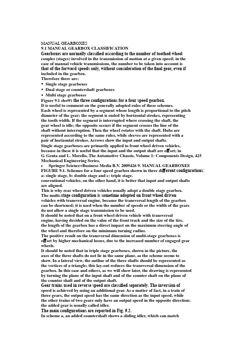
MANUAL GEARBOXES9.1 MANUAL GEARBOX CLASSIFICATIONGearboxes are normally classified according to the number of toothed wheelcouples (stages) involved in the transmission of motion at a given speed; in thecase of manual vehicle transmissions, the number to be taken into account isthat of the forward speeds only, without consideration of the final gear, even if included in the gearbox.Therefore there are:•Single stage gearboxes•Dual stage or countershaft gearboxes•Multi stage gearboxesFigure 9.1 sho ws the three configurations for a four speed gearbox.It is useful to comment on the generally adopted rules of these schemes.Each wheel is represented by a segment whose length is proportional to the pitch diameter of the gear; the segment is ended by horizontal strokes, representingthe tooth width. If the segment is interrupted where crossing the shaft, thegear wheel is idle; the opposite occurs if the segment crosses the line of theshaft without interruption. Then the wheel rotates with the shaft. Hubs are represented according to the same rules, while sleeves are represented with apair of horizontal strokes. Arrows show the input and output shafts.Single stage gearboxes are primarily applied to front wheel driven vehicles,because in these it is useful that the input and the output shaft are offset; inG. Genta and L. Morello, The Automotive Chassis, Volume 1: Components Design, 425 Mechanical Engineering Series,c Springer Science+Business Media B.V. 2009426 9. MANUAL GEARBOXES FIGURE 9.1. Schemes for a four speed gearbox shown in three different configurations: a: single stage, b: double stage and c: triple stage.conventional vehicles, on the other hand, it is better that input and output shaftsare aligned.This is why rear wheel driven vehicles usually adopt a double stage gearbox.The multi-stage configuration is sometime adopted on front wheel drivenvehicles with transversal engine, because the transversal length of the gearboxcan be shortened; it is used when the number of speeds or the width of the gearsdo not allow a single stage transmission to be used.It should be noted that on a front wheel driven vehicle with transversalengine, having decided on the value of the front track and the size of the tire,the length of the gearbox has a direct impact on the maximum steering angle ofthe wheel and therefore on the minimum turning radius.The positive result on the transversal dimension of multi-stage gearboxes isoffset by higher mechanical losses, due to the increased number of engaged gear wheels.It should be noted that in triple stage gearboxes, shown in the picture, theaxes of the three shafts do not lie in the same plane, as the scheme seems toshow. In a lateral view, the outline of the three shafts should be represented asthe vertices of a triangle; this lay-out reduces the transversal dimension of the gearbox. In this case and others, as we will show later, the drawing is representedby turning the plane of the input shaft and of the counter shaft on the plane ofthe counter shaft and of the output shaft.Gear trains used in reverse speed are classified separately. The inversion ofspeed is achieved by using an additional gear. As a matter of fact, in a train ofthree gears, the output speed has the same direction as the input speed, whilethe other trains of two gears only have an output speed in the opposite direction;the added gear is usually called idler.The main configurations are reported in Fig. 9.2.In scheme a, an added countershaft shows a sliding idler, which can matchtwo close gears that are not in contact, as, for example, the input gear of thefirst speed and the output gear of the second speed. It should be noted that, inthis scheme, the drawing does not preserve the actual dimension of the parts.9.1 Manual gearbox classification 427FIGURE 9.2. Schemes used for reverse speed; such schemes fit every type of gearboxlay-out.Scheme b shows instead two sliding idlers, rotating together; this arrange-ment offers additional freedom in obtaining a given transmission ratio. The coun-tershaft is offset from the drawing plane; arrows show the gear wheels that matchwhen the reverse speed is engaged.Scheme c is similar to a in relation to the idler; it pairs an added specificwheel on the output shaft with a gear wheel cut on the shifting sleeve of the firs tand second speed, when it is in idle position.Configuration d shows a dedicated pair of gears, with a fixed idler and ashifting sleeve.The following are the advantages and disadvantages of the configurationsshown in the figure.•Schemes a, b and c are simpler, but preclude the application of synchro-nizers (because couples are not always engaged), nor do they allow the useof helical gears (because wheels must be shifted by sliding).•Scheme d is more complex but can include a synchronizer and can adopthelical gears.•Schemes a, b and c do not increase gearbox length.428 9. MANUAL GEARBOXES9.2 MECHANICAL EFFICIENCYThe mechanical efficiency of an automotive gear wheel transmission is high com-pared to other mechanisms performing the same function; indeed, the value ofthis efficiency should not be neglected when calculating dynamic performanceand fuel consumption. The continuous effort of to limit fuel consumption justi-fies the care of transmission designers in reducing mechanical losses.Total transmission losses are conveyed up by terms that are both dependentand independent of the processed power; the primary terms are:•Gearing losses; these are generated by friction between engaging teeth(power dependent) and by the friction of wheels rotating in air and oil(power independent).•Bearing losses; these are generated by the extension of the contact area ofrolling bodies and by their deformation (partly dependent on and partlyindependent of power) and by their rotation in the air and oil (powerindependent).•Sealing losses; they are generated by friction between seals and rotatingshafts and are power independent.•Lubrication losses; these are generated by the lubrication pump, if present,and are power independent.All these losses depend on the rotational speed of parts in contact and,therefore, on engine speed and selected transmission ratio.Table 9.1 reports the values of mechanical efficiency to be adopted in calcu-lations considering wide open throttle conditions; these values consider a pair ofgearing wheels or a complete transmission with splash lubrication; in the sametable we can see also the efficiency of a complete powershift epicycloidal auto-matic transmission and a steel belt continuously variable transmission. For thetwo last transmissions, the torque converter must be considered as locked-up.TABLE 9.1. Mechanical efficiency of different transmission mechanisms.Mechanism type Efficiency (%)Complete manual gearboxwith splash lubrication 92–97Complete automatic transmission(ep. gears) 90–95Complete automatic gearbox(steel belt; without press. contr.) 70–80Complete automatic gearbox(steel belt; with press. contr.) 80–86Pair of cyl. gears 99.0–99.5Pair of bevel gears 90–939.2 Mechanical efficiency 429FIGURE 9.3. Contributions to total friction loss of a single stage gearbox designed for300 Nm as function of input speed.It is more correct to reference power loss measurement as a function ofrotational input speed rather than efficiency. Figure 9.3 shows the example ofa double stage transmission, in fourth speed, at maximum power; the differentcontributions to the total are shown.This kind of measurement is made by disassembling the gearbox step bystep, thus eliminating the related loss.In the first step all synchronizer rings are removed, leaving the synchronizerhubs only; mechanical losses of non-engaged synchronizers are, therefore, mea-surable. The loss is due to the relative speed of non-engaged lubricated conicalsurfaces; the value of this loss depends, obviously, on speed and the selectedtransmission ratio.In the second step all rotating seals are removed.In the third step the lubrication oil is removed, and therefore, the bulk ofthe lubrication losses is eliminated; some oil must remain in order to leave thecontact between teeth unaffected.By removing those gear wheels not involved in power transmission, theirmechanical losses are now measurable.The rest of the loss is due to bearings; the previous removal of parts canaffect this value.A more exhaustive approach consists in measuring the complete efficiencymap; the efficiency can be represented as the third coordinate of a surface, wherethe other two coordinates are input speed and engine torque. Efficiency calcu-lations can be made by comparing input and output torque of a working trans-mission.Such map can show how efficiency reaches an almost constant value at amodest value of the input torque; it must not be forgotten that standard fuelconsumption evaluation cycles involve quite modest values of torque and there-fore imply values of transmission efficiency that are changing with torque.Figure 9.4 shows a qualitative cross section of the aforesaid map, cut atconstant engine speed. It should be noted that efficiency is also zero at input430 9. MANUAL GEARBOXESFIGURE 9.4. Mechanical efficiency map, as a function of input torque at constantengine speed; the dotted line represents a reasonable approximation of this curve, to beused on mathematical models for the prediction of performance and fuel consumption.torque values slightly greater than zero; as a matter of fact, friction implies acertain minimum value of input torque, below which motion is impossible.A good approximation to represent mechanical efficiency can be made usingthe dotted broken line as an interpolation of the real curve.9.3 MANUAL AUTOMOBILE GEARBOXES9.3.1 Adopted schemesIn manual gearboxes, changing speed and engaging and disengaging the clutchare performed by driver force only.This kind of gearbox is made with helical gears and each speed has a syn-chronizer; some gearboxes do not use show the synchronizer for reverse speed,particularly those in economy minicars.We previously discussed a first classification; additional information is thespeed number, usually between four and six.Single stage gearboxes are used in trans-axles; they are applied, with someexceptions, to front wheel driven cars with front engine and rear driven cars withrear engine; this is true with longitudinal and transversal engines.In all these situations the final drive is included in the gearbox, which istherefore also called transmission.Countershaft double stage gearboxes are used in conventionally driven cars,where the engine is mounted longitudinally in the front and the driving axle isthe rear axle. If the gearbox is mounted on the rear axle, in order to improve theweight distribution, the final drive could be included in the gearbox.9.3 Manual automobile gearboxes 431By multi-stage transmissions, some gear wheels could be used for differentspeeds. The number of gearing wheels could increase at some speeds; this nor-mally occurs at low speeds, because the less frequent use of these speeds reducesthe penalty of lower mechanical efficiency on fuel consumption.Cost and weight increases are justified by transmission length reduction,sometimes necessary on transversal engines with large displacement and morethan four cylinders.In all these gearboxes synchronizers are coupled to adjacent speeds (e.g.:first with second, third with fourth, etc.) in order to reduce overall length andto shift the two gears with the same selector rod.We define as the selection plane of a shift stick (almost parallel to the xzcoordin ate body reference system plane for shift lever on vehicle floor) the planeon which the lever knob must move in order to select two close speed pairs. Forinstance, for a manual gearbox following many existing schemes, first, second,third, fourth and fifth speed are organized on three different selection planes; thereverse speed can have a dedicated plane or share its plane with the fifth speed.Figure 9.5 shows a typical example of a five speed single stage gearbox. Thefirst speed wheels are close to a bearin g, in order to limit shaft deflection.In this gearbox the total number of tooth wheels pairs is the same as forthe double stage transmission shown in Fig. 9.6.While in the first gearbox there are only two gearing wheels for each speed,in the second there are three gearing wheels for the first four speeds and noneFIGURE 9.5. Scheme for a five speed single stage transmission, suitable for front wheeldrive with transversal engine.432 9. MANUAL GEARBOXESFIGURE 9.6. Scheme of an on-line double stage gearbox for a conventional lay-out.for the fifth. This property is produced by the presence of the so called constantgear wheels (the first gear pair at the left) that move the input wheels of thefirst four speeds; the fifth speed is a direct drive because the two p arts of theupper shaft are joined together.The single stage gearbox in Fig. 9.5 shows the fifth speed wheel pair posi-tioned beyond the bearing, witness to the upgrading of an existing four speedtransmission; in this case the fifth speed has a dedicated selection plane.The double stage gearbox in Fig. 9.7 is organized in a completely differentway but also shows the first speed pair of wheels close to the bearing. The directdrive is dedicated to the highest speed; the fifth speed shows a dedicated selectio nplane.Six speed double stage gearboxes do not show conceptual changes in com-parison with the previous examples; synchronizers are organized to leave firstand second, third and fourth, fifth and sixth speeds on the same selection plane.As already seen, the multistage configuration shown in Fig. 9.7 allows areasonable reduction of the length of the gearbox. In this scheme, only first andsecond speeds benefit from the second countershaft; power enters the counter-shaft through a constant gear pair of whee ls and flows to the output shaft at areduced speed. Third, fourth and fifth speed have a single stage arrangement.Reverse speed is obtained with a conventional idling wheel.9.3.2 Practical examplesFour speed gearboxes represented the most widely distributed solution in Europeuntil the 1970s, with some economy cars having only three speeds.9.3 Manual automobile gearboxes 433FIGURE 9.7. Scheme of a triple stage five speed gearbox, suitable for front wheel drivencar with transversal engine.With the increase in installed power, the improvement in aerodynamic per-formance and increasing attention to fuel consumption, it became necessary toincrease the transmission ratio of the last speed, having the first speed remain atthe same values; as a matter of fact car weight continued to increase and engineminimum speed did not change significantly.To achieve satisfactory performance all manufacturers developed five speedgearboxes; this solution is now standard, but many examples of six speed gear-boxes are available on the market, not limited to sports cars.Figure 9.8 shows an example of a six speed double stage transmission withthe fifth in direct drive; here the first and second pair of wheels are close to thebearing.This rule is not generally accepted; on one hand having the most stressedpairs of wheels close to the bearing allows a shaft weight containment. On theother hand, having the most frequently used pairs of wheels close to the bearingreduces the noise due to shaft deflection.Synchronizers of fourth and third speed are mounted on the countershaft;this lay-out reduces the work of synchronization, improving shifting quality by anamount proportional to the dimension of the synchronizing rings. Synchronizersof first and second gear on the output shaft are, because of their diameter, larger434 9. MANUAL GEARBOXESFIGURE 9.8. Double stage six speed gearbox (GETRAG).than those of the corresponding gear; the penalty of the synchronization work ispaid by the adoption of a double ring synchronizer.Synchronizers on the countershaft offer a further advantage: In idle positionthe gears are stopped and produce no rattle; this subject will be studied later on.9.3 Manual automobile gearboxes 435Figure 9.9 introduces the example of a single stage gearbox for a frontlongitudinal engine. The input upper shaft must jump over the differential, whichis set between the engine and the wheels. The increased length of the shaftssuggested adopting a hollow section. Because of this length the box is dividedinto two sections; on the joint between the two sections of the box additionalbearings are provided to reduce the shaft deflection.The input shaft features a ball bearing close to the engine and three otherneedle bearings that manage solely the radial loads. The output shaft has twotapered roller bearings on the differential side and a roller bearing on the oppositeside. This choice is justified by the relevant axial thrust emerging from the bevelgears.The first and second speed synchronizers are on the output shaft a nd featurea double ring.The reverse speed gears are placed immediately after the joint (the idlergear is not visible) and have a synchronized shift. Remaining synchronizers areset in the second section of the box on the input shaft. The output shaft endswith the bevel pinion, a part of the final ratio.It should be noted that the gears of the first, second and reverse speeds aredirectly cut on the input shaft, in order to reduce overall dimensions.Most contemporary cars use a front wheel drive with transversal engine; thenumber of gearboxes with integral helical final ratio is, therefore, dominant.In these gearboxes geared pairs are mounted from the first to the last speed,starting from the engine side. An example of this architecture is given in Fig. 9.10.Like many other transmissions created with only four speeds, it shows thefifth speed segregated outside of the aluminium box and enclosed by a thin steelsheet cover; this placement is to limit the transverse dimension of the powertrain, in the area where there is potential interference with the left wheel in thecompletely steered position.This solution is questionable as far as the total length is concerned but showssome advantage in the reduction of the span between the bearings. Each bearingis of the ball type; on the side opposite to the engine the external ring of thebearing can move axially, to compensate for thermal differential displacements.One of the toothed wheels of the reverse speed is cut on the first and secondshifting sleeve.The casing is open on both sides; one of these is the rest of one of thebearings of the final drive. A large cover closes the casing on t he engine side and,in the meantime, provides installation for the second bearing of the final driveand the space for the clutch mechanism; it is also used to join the gearbox tothe engine.In this gearbox synchronizers are placed partly on the input shaft and partlyon the output shaft.Figure 9.11 shows a drawing of a more modern six speed gearbox, in whichit was possible to install all the gears in a conventional single stage arrangement,thanks to the moderate value of the rated torque.436 9. MANUAL GEARBOXESFIGURE 9.9. Single stage six speed gearbox for longitudinal front engine (Audi).9.4 Manual gearboxes for industrial vehicles 437FIGURE 9.10. Five speed transmission for a transversal front engine (FIAT).Gears are arranged from the first to the sixth, starting from the engineside; as we have already said this arrangement is demanded by the objectiveof minimizing shaft deflection. Only the synchronizers of first and second speedfound no place on the input shaft; they are of the double ring type, as for thefirst speed.The reverse speed is synchronized and benefits of a countershaft not shownin this drawing.9.4 MANUAL GEARBOXES FOR INDUSTRIALVEHICLES9.4.1 Lay-out schemesThe gearboxes we are going to examine in this section are suitable for vehicles ofmore than about 4 t of total weight; lighter vehicles, usually called commercialvehicles, adopt gearboxes that are derived from automobile production, as notedin the previous section.438 9. MANUAL GEARBOXESFIGURE 9.11. Six speed transmission for a transversal front engine (FIAT).Gearboxes used in industrial vehicles also feature synchronizers; they can beshifted directly, as in a conventional manual transmission, or indirectly with theassistance of servomechanisms. Non-synchronized gearboxes are sometimes usedon long haul trucks, because of their robustness. Assisted shifting mechanismsare widespread because of the easy availability of power media. Automatic orsemi-automatic transmis sions are also used, the first type especially in buses.For gearboxes with four up to six speeds, the double stage countershaftarchitecture represents a standard; the scheme is the same as seen before.The constant gear couple is used for all speeds but the highest. Also notableis that the lowest speed wheels are close to the bearings.As shown in the drawings of Fig. 9.12, the highest speed can be obtainedeither in direct drive (scheme b) or with a pair of gears (scheme a); in this lastcase the direct drive is used for the speed before the last: these architectures arecalled direct drive and overdrive.In the figure, only the last and the first before the last speed are represented.The choice between the two alternatives can be justified by the differentvehicle mission; virtually the same gearbox can be used on different vehicleswith different frequently used speeds (a truck and a bus for example).9.4 Manual gearboxes for industrial vehicles 439FIGURE 9.12. Alternative constant gear schemes with last or first before the last speedin direct drive.Sometime the constant gear is set on the output shaft, after the differentspeed gears; this configuration offers the following advantages:•Reduction of the work of synchronization, because of the smaller gear di-mension at the same torque and total transmission ratio•Less stress on the input shaft and countershaftOn the other hand, the following disadvantages emerge:•Bearings rotate faster.•Constant gear wheels are more highly stressed.This applies for single range transmissions.Multiple range transmissions feature, in addition to the main gearbox, othergearboxes that multiply the number of speeds of the main gearbox by the numberof their speeds. With this architecture the total number of gear pairs might bereduced, for a given number of speeds, and, sometime the use of the gearshiftlever can be simpler.This arrangement is used when more than six speeds are necessary. A multi-ple range transmission is therefore made out of a combination of different coun-tershaft gearboxes, single range gearboxes or epicycloidal gearboxes.Each added element is called a range changer if it is conceived as beingcapable of using the main gearbox speeds in sequence, in two completely non-overlapping series of vehicle speeds; for example, if the main gearbox has fourspeeds, the first speed in the high range is faster than the fourth speed in thelow range.The element is called a splitter if it is intended to create speeds that areintermediate to those of the main gearbox; in this case, for example the third440 9. MANUAL GEARBOXESFIGURE 9.13. Scheme of a 16 speed gearbox for industrial vehicles; it is made with afour gear main gearbox, a double speed splitter and a double speed range changer withdirect drive.speed in the high range is faster than the third speed in the low range, but slowerthan the fourth speed in the low range.We call the gearbox with the highest number of speeds the main gearbox;the splitter and the range changer will be set in series before and after the maingearbox.Figure 9.13 shows the scheme of a gearbox featuring a splitter and a rangechanger. The splitter is made out of a pair of wheels that work as two differentconstant gears for the main gearbox. The countershaft can therefore be movedat two different speeds, according to the position of the splitter unit. Becausethe main gearbox has four speeds, this splitter unit can create a total of eightspeeds, one of them being in direct drive.At the output shaft of this assembly, there is a range changer unit madeas a two speed double stage gearbox with direct drive; this unit multiplies bytwo the total number of obtainable speeds. The range changer is qualified by the significant difference between the two obtainable speeds.The range changer can be made with a countershaft gearbox or an epicy-cloidal gearbox with direct drive; the advantage in the latter case is the possi-bility of an easier automatic actuation, by braking some of the elements of the epicycloidal gear.9.4 Manual gearboxes for industrial vehicles 441FIGURE 9.14. Transmission ratios obtained with the scheme of transmission shown in Fig. 9.15; speed identification shows the main gearbox speed with the number, the splitter position with the first letter, the range changer position wi th the second; L stands for low, H stands for high.It is also possible to place the range changer before the main gearbox andthe splitter unit after the main gearbox.A different way of defining the functions of range change units is to say thatthe splitter is a gearbox that compresses the gear sequence, because it reducesthe gap between speeds, while the range changer is a gearbox that expands the gear sequence, because it increases the total range of the transmission.Figure 9.14 explains the concept of compression; the bars represent the ratios obtained in all shifting lever positions. Ratios obtained with the splitter unit inthe L position (the first letter in the speed identification, L stands for lower ratio) are interspersed with the ratios obtained with the splitter unit in the H position (H stands for higher ratio, in this case 1:1) and reduce the amplitude of the gear steps of the main gearbox.The same figure also explains the concept of expansion, showing on thesame graph the ratio obtained with the range changer in the H position (second identification letter) and the L position; the gear step between the first in lowgear and the first in high gear is as big as the range of the main gearbox, andthe total transmission range is widened.The range changer is therefore seldom used, when driving conditions change suddenly, as, for example, when leaving a normal road for a country road that must be driven more slowly, or when encountering a strong slope with a fully loaded vehicle. The splitter allows the dynamic performance of the vehicle to be improved, making the optimum transmission ratio available to obtain the desired power. The splitter is therefore used frequently. In a fully loaded vehicle, for example, all split ratios can be used in sequence during full throttle acceleration from a standstill.442 9. MANUAL GEARBOXESThe range changer and splitter are usually made as modular units that canbe mounted at both ends of the main gearbox, or changed with simple covers,in order to satisfy all application needs with limited total production costs. Generalizing these concepts could suggest building transmissions using ad- ditional range changing units arranged in series. These could be conceived as being made only of splitter units with direct drive.In such a case, with n pairs of tooth wheels it is possible to obtain a totalof z transmission ratios, given by the formula:z =2n−1. (9.1)The formula expresses the number of possible states that can be obtainedfrom n − 1 pairs of gears; one unit is subtr acted because one pair must be a constant gear to move the countershaft.With four pairs of gears, for example, four speeds can be obtained in adouble stage gearbox; while using a cascade of splitters eight different speeds could be obtained. The goal of good shift manoeuvrability and the implicationsfor mechanical losses must not be forgotten, while defining the best architecture. Figure 9.15 shows the scheme of the 16 speed transmission with splitter andrange changer we already described. In this picture are represented the spans of。
汽车自动变速外文翻译英文共6页word资料

文章编号:1006—8244(2019)03—03—10The ZF··AS Tronic Family·-Automotive Transmissions for AII Commercial Vehicle ClassesDr.Frank-Detlef Speck,Marcus Raeder,Dr.Christoph Riichardt,[Abstract]ZF developed a new automatic transmission--AS Tronic Family,which can fulfill the customers requirements.The AS Tronic Family covers trucks in the lower torque range up to 2600Nm and has 6、10、12 and 16 speed.The AS Tronic can make an important contribution in ruel consumption.10w noise emissions,more comfortable driving and safely traffic.1 Requirements for Commercial Vehicle TransmissionsCustomers demand high efficiency along with in—creasing vehicle comfort and safety.As an inder pendent transmission manufacturer,ZF customer needs include the needs of drivers,forwarding companiis,and vehicle manufacturers.Therefore,ZF considers the many requirements that a new transmission concept must fulfill when developing a transmission,Figure 1.Keeping costs low is a considerable challenge,initially in terms of acquisition and later during operation.That is why fuel consumption is increasingly one of the decisive vehicle features that separate the petition.A modern transmission can make an important contribution here:On the one hand by improving efficiency and on the other hand in automatic transmissions by the optimal selection of the gear ratio dependent on the driving situation.Redueing the transmission weight also leads to redued costs:Using less material reduces acquisition costs and enabling a higher payload reduces operating costs.On the one hand。
汽车变速器的设计外文文献翻译、中英文翻译、外文翻译
汽车变速器的设计外文文献翻译、中英文翻译、外文翻译A manual n。
also known as a standard n。
XXX。
It consistsof gears。
synchros。
roller bearings。
shafts。
and gear selectors。
The main clutch assembly is used to engage and disengage the engine from XXX gears are used to select the desired。
and the sector fork moves gears from one to another using the gearshift knob。
Synchros are used to slow the gear to a。
before it is XXX。
The counter shaft holds the gears in place and against the main input and output shaft。
Unlike automatic ns。
XXX。
as there isno XXX。
Note: XXX "n Shifter" was deleted as it had no XXX.)XXX have four to six forward gears and one reverse gear。
However。
some cars may have up to eight forward gears。
while semi trucks XXX by the number of forward gears。
such as a 5-speed standard n.The n of a standard n includes three shafts: the input shaft。
中英文文献翻译—AMT变速器
附录附录A电控机械式自动变速器(AMT)是在传统的手动齿轮式变速器基础上改进而来的;它揉合了 AT(自动)和 MT(手动)两者优点的机电液一体化自动变速器;AMT既具有液力自动变速器自动变速的优点,又保留了原手动变速器齿轮传动的效率高、成本低、结构简单、易制造的长处。
它揉合了二者优点,是非常适合我国国情的机电液一体化自动变速器。
它是在现生产的机械变速器上进行改造的,保留了绝大部分原总成部件,只改变其中手动操作系统的换档杆部分,生产继承性好,改造的投入费用少,非常容易被生产厂家接受。
它的缺点是非动力换档,这可以通过电控软件方面来得到一定弥补。
在几种自动变速器中,AMT的性价比最高。
AMT用先进的电子技术改造传统的手动变速器,不仅保留了原齿轮变速器效率高、低成本的长处,而且还具备了液力自动变速器采用自动换档所带来的全部优点。
它以特有的经济、方便、安全、舒适性而备受所有驾驶者的欢迎,成为各国开发的热点。
驾驶员通过加速踏板和操纵杆向电子控制单元(ECU)传递控制信号;电子控制单元采集发动机转速传感器、车速传感器等信号,时刻掌握着车辆的行驶状态;电子控制单元(ECU)根据这些信号按存储于其中的最佳程序,最佳换档规律、离合器模糊控制规律、发动机供油自适应调节规律等,对发动机供油、离合器的分离与结合、变速器换档三者的动作与时序实现最佳匹配。
从而获得优良的燃油经济性与动力性能以及平稳起步与迅速换档的能力,以达到驾驶员所期望的结果。
AMT是对传统干式离合器和手动齿轮变速器进行电子控制实现自动换档的新式变速器,其控制过程基本是模拟驾驶员的操作。
控制单元(ECU)的输入有:驾驶员的意图-加速踏板、档位选择;汽车的工作状态-发动机转速、节气门开度、车速等。
控制单元(ECU)根据换档规律、离合器控制规律、发动机节气门自适应调节规律产生的输出,对节气门开度、离合器、换档操纵三者进行综合控制,有效配合。
AMT由于继承了齿轮传动固有的传动效率高、机构紧凑、工作可靠等优点,并可以实现手动和自动两种模式选择,因此有较强的可靠性和适应性。
汽车变速器变速箱外文文献翻译、中英文翻译、外文翻译

TRANSMISSIONOf all transmission technologies, the manual gearbox is the most efficient; around 96 per cent of the energy that is put in comes out of the other end. But not everyone can drive one or wants to. Because you have to dip the clutch pedal, it is less comfortable to drive in heavy traffic. It makes the driver tired and the torque interruptions’ head-nod effect on passengers can be wearing.The driver's clutch control and corresponding torque interruptions are also the manuals weak point. When accelerating up through the gearbox, each up-shift requires the driver to cut the torque momentarily by lifting the gas pedal and dipping the clutch. It may just take a second to complete the operation, but during this time the vehicle is losing speed and acceleration.At the opposite end of the spectrum is the traditional automatic. The modern transmission is by far, the most complicated mechanical component in today’s automobile. It is a type of transmission that shifts itself .A fluid coupling or torque converter is used instead of a manually operated clutch to connect the transmission to the engine.There are two basic types of automatic transmissions based on whetherthe vehicle is rear wheel drive . On a rear wheel drive car , the transmission is usually mounted to the back of the engine and is located under the hump in the center of the floorboard alongside the gas pedal position . A drive shaft connects the rear of the transmission to the final drive which is located in the rear axle and is used to send power to the rear wheel. Power flow on this system is simple and straight forward going from the engine, through the torque converter , then through the transmission and driver shaft until it reaches the final driver where it is split and sent to the two rear wheel .On a front wheel drive car, the transmission is usually combined .With the final drive to from what is called a transaxle. The engine on a front wheel driver car is usually mounted sideways in the car with the transaxle tucked under it onthe side of the engine facing the rear of the car. Front axles are connected directly to the transaxle and provide power to the front wheels. In this example, power flows from the engine through the torque converter to a large chain that sends the power through a 180 degree turn to the transmission that is along side the engine. From there,The power is routed through the transmission to the final drive where it is split and sent to the two front wheels through the drive axles.There are a number of other arrangements including front drive vehicles where the engine is mounted front to back instead of sideways and there are other systems that drive all four wheels but the two systems described here are by far the most popular. A must less popular rear drive arrangement has the transmission mounted to the final drive at the rear and is connected by a drive shaft to the torque converter which is still mounted on the engine. This system is found on the new corvette and is used in order to balance the weight evenly between the front and rear wheels for improved performance and handling. Another rear drive system mounts everything, the engine, transmission and final drive in the rear. This rear engine arrangement is popular on the Porsche.The modern automatic transmission consists of many components and systems that are designed to work together in a symphony of planetary gear sets, the hydraulic system, seals and gaskets, the torque converter, the governor and the modulator or throttle cable and computer consider being an art form.On the automobile planet gear mainly uses in two places, one is the driving axle reduction gear, two is the automatic transmission. Very many net friends all want to know that, the planet gear has any function, why automobile must have it . We knew very well the gear major part all rotates the spool thread fixed gear. For example mechanical type clock and watch, above all gears although all in make the rotation, but their rotation center (with center of a circle position superposition) often installs through the bearing on the cabinet, therefore, their rotating axis all is the relative cabinet fixed, thus also is called "dead axle gear" . Has must have surely moves, the corresponding place, some kind of not that manner knows very well is called "planet gear" the gear, their rotation spool thread is not fixed, but is installs the support which may rotate in (blue color) on(in chart black part is shell, yellow expression bearing). The planet gear (green) besides can look like the dead axle gear such to revolve own rotating axis (B-B) to rotate, their rotating axis also (is called planet) along with the blue color support to circle other gears the spool thread (A-A) to rotate. Circles oneself spool thread the rotation to be called "rotation", circles other gear spool threads the rotation to be called "revolution", looks like in solar system planet such, therefore acquires fame.The spool thread fixed gear drive principle is very simple, meshes mutually in a pair in the gear, some gear takes the driving pulley, the power spreads from its there, another gear takes the driven wheel, the power outputs from it toward outside. Also some gears only take the stopover station, at the same time meshes with the driving pulley, one side meshes in addition with the driven wheel, the power passes from its there.In contains the planet gear in the gear system, the situation was different. Because has the planet frame, in other words, may have three rotating axes permissions power input/Output, but also may use the coupling or the brake and so on method. in needs time limits axis the rotation, is left over two axes to carry on the transmission, as the matter stands, meshes mutually between the gear relations may have the many kinds of combinations: The power from sun gear input, outputs from other sun gear, the planet put through brake mechanism has checked dies; Power from sun gear input, from planet output, moreover a sun gear ecks dies; The power from a planet input, outputs from sun gear, moreover a sun gear checks dies; Two powers separately from two sun gears inputs, after synthesis from planet output; Two powers separately from the planet and sun gear input, after the synthesis output from other sun gear; The power from sun gear input, divides two groups outputs from other sun gear and the planet frame; The power from a planet input, divides two groups to output from two sun gears;Its shift quality is good thanks to its torque converter, but efficiency is relatively poor despite recent advances. Because of this, a lot of the current research is trying to find an efficient alternative to the conventional automatic.The main technologies are continuously variable transmissions (CVTs); dualclutch transmissions (DCTs) and automated manual transmission (AMTs).They all offer different benefits over the conventional planetary automatic.The CVT uses a belt chain or torodial shaped dish drive to vary an infinite number of gear ratios. It has improved efficiency and cost when compared to conventional automatics. Its advantage comes from its simplicity. It consists of very few components;usually a rubber or metal-link belt;a hydraulically operated driving pulley, a mechanical torque-sensing driving pulley, microprocessors and some sensors.The transmission works by varying the distance between the face of the two main pulleys. The pulleys have V-shaped grooves in which the connecting the belt rides. One side of the pulley is fixed axially; the other side moves, actuated by hydraulics.When actuated, the cylinder can increase or reduce the amount of space between the two sides of the pulley. This allows the belt to ride lower or higher along the walls of the pulley, depending on driving conditions. This changes the gear ratio. A torodial-type design works in a similar way but runs an discs and power- rollersThe "step less" nature of its design is CVT's biggest draw for automotive engineers .Because of this, a CVT can work to keep the engine in its optimum power range, thereby increasing efficiency and mileage. A CVT can convert every point on the equine’s operating curve to a corresponding point on its own operating curve.The transmission is most popular with Japanese carmakers and Japanese supplier JATCO is a major producer. But in the US and Europe driving styles are different. Uptake has been slow despite Audi and other manufacturers having Offered CVT operations on their ranges.The DCT is, in effect, two manual gearboxes coupled together. Gear shifts are made by switching from one clutch on one gearbox to another clutch on the other. The shift quality is equal to a conventional automatic, but slip, fluid drag and hydraulic losses in the system result in only slightly improved efficienc y and acceleration over the conventional planetary automatic. Developing the controlstrategy is costly too."Resent advances in conventional automatic technology have weakened the argument to develop and set up production for CVT or DCT," says Bill Martin, managing director of transmission firm Zeroshift "Some carmakers have cancelled DCT projects because of the cost."The cheapest way to build an automatic is with an AMT. AMTs use actuators to replace the clutch pedal and gear stick of a conventional manual. They keep the high efficiency and acceleration of a manual gearbox, but the shift quality on some models is lacking. Torque interruptions and the head-nod effect are the most common complaint.SO what is the alternative? There are always new ideas in transmissions, but Zeroshift says that its technology has efficiency benefits over a manual, delivering fuel economy improvements to city driving. Shift quality can also be equal to that of a refined automatic.Zeroshift's approach is an upgrade to the AMT. The synchromesh is replaced with an advanced dog engagement system.Dog engagement has been used for many years in motor sport to allow fast shifts. Conventional dog Boxes are unsuitable for road use as the large spaces between the drive lugs or 'dogs" create backlash, an uncomfortable shunt caused by the sudden change in torque direction.Zeroshift's technology solves this problem by adding a second set of drive dogs. It has also made each of The two sets of dogs only capable of transmitti ng torque in one or other opposing directions错误!未找到引用源。
- 1、下载文档前请自行甄别文档内容的完整性,平台不提供额外的编辑、内容补充、找答案等附加服务。
- 2、"仅部分预览"的文档,不可在线预览部分如存在完整性等问题,可反馈申请退款(可完整预览的文档不适用该条件!)。
- 3、如文档侵犯您的权益,请联系客服反馈,我们会尽快为您处理(人工客服工作时间:9:00-18:30)。
附录1:外文翻译
自动五速手动变速箱- EASYTRONIC 3.0。
The new Opel/Vauxhall公司在2014年秋季推出了自动化五速手动变速箱(MTA) Easytronic 3.0。
该变速器使用电动液压离合器和位移控制,其主要部件主来自手动变速箱(F17-5)。
这个新的变速器新增了停止/启动功能,而他的控制系统是根据安全标准ISO 26262设计的。
DIPL.-ING。
THOMAS ZEMMRICH是德国Adam Opel公司变速器自动化MT系统组长和技术专家。
持续战略
2014年秋季,欧宝/沃克斯豪尔公司引进了新一代自动化手动变速器MTA(手动变速器) Easytronic 3.0。
这延续了公司自2001年开始战略,通过这种低成本的变速器有效代替小型车辆的常规自动变速器。
由于传统变速器在传动过程中有扭矩中断会使车辆在驾驶时舒适度不佳。
因此,他们设计了与传统变速箱相比操作操作更简便,燃油经济性更好的,并且带有运动驾驶风格的自动化变速器。
这篇文章介绍了欧宝新推出的MTA 的设计和性能特点。
变速器的设计
这款新推出的变速器是在Opel公司五速手动变速箱(F17-5)的基础上开发的,它的扭矩容量为190Nm。
这款变速器用在中小型汽油发动机手动档车型上的排量高达1.4L,用在材油机手动挡车型上的排量为1.3L。
虽然拥有高达200Nm转矩容量的6速变速箱越来越受到欢迎,但是考虑到成本,目前五速版的变速箱任是小型汽车的首选。
这款变速器采用拨叉和同步器进行换档,所选的齿轮组传动比范围为5.53,这对于一个五速变速箱来说是一个相当大的传动比范围。
由于较大的传动比范围,使得一档工作时不需要输入较大的转矩,使驾驶舒适性能得到提高,且在五档工作时不需要发动机输入较高的转速就可以获得较高的驾驶速度,还能够降低噪音,提高燃油经济性。
后者是实现自动手动变速器而不损失任何性能,因为加速度可以通过快速自动降档来实现。
变速器需要能够在自动和手动模式中使用同样的离合器。
且没有MTA特定的修改是必须要车辆集成显示变速器的基本数据。
与以前的机电系统〔1〕相比,电动液压执行器接管离合器和换档。
在新的MTA中操作。
其主要部件包括电动机、泵、蓄压器、油箱、带有电磁阀的块和直接与阀门接触的控制模块(机电一体化)。
与较早的电液系统相比,新一代的驱动以更高的集成度来区分。
所有的部件都安装在一个底板上,它包括液压管道,因此没有外部液压管路。
所有内部传感器(移位/选择)在没有布线的情况下也接触位置和压力。
这些特性在成本、质量、封装和系统可靠性方面提供了好处。
为了测量输入轴速度,新的MTA配备了速度传感器,使用霍尔效应原理。
以第四齿轮作为目标,不需要单独的目标轮,因此手动变速器中的所有轴在自动应用中都可以使用不变。
在手动变速器中,离合器操作采用液压同心从动油缸(CSC),但不需要主缸,而驱动系统液压通常使用液压油代替制动液。
比例阀接管油流量的调节。
CSC还配备了非接触式行程传感器(霍尔效应),这给控制器提供了离合器释放行程闭环控制所需的反馈。
目标是一个连接到离合器的磁体。
CSC位置测量的优点是动态和温度引起的效应。
液压回路包含在控制回路中,而不是测量主缸上的位置。
另一方面,CSC的发动机运转的轴向脉动也由传感器检测并叠加在行驶信号上。
在传输控制器中的原始信号的处理过程中,适当的滤波补偿了这种影响。
功能
新的MTA提供可选择的自动或手动操作模式,并且还支持运动模式功能以及巡航控制。
在自动模式中,具有更多功能的许多移位映射是可用的[2 ]。
一个新特性是在低速条件下抑制2-1的降档。
它在第二档运行离合器,只要没有更高的牵引力需求,就可以换档至第一档。
进一步发展的升档防止功能保证在适当的驱动加速度下也能选择合适的齿轮,例如在上坡行驶或拖曳时,或由于高度或热而减少发动机扭矩。
与优化的移位映射一样,这些特殊功能使移位频率显著降低。
在欧宝测试周期中,换档次数从现有的欧宝五速MTA的231减少到新版本的195档。
这有助于提高驾驶舒适性,降低油耗。
新MTA的另一个目标是优化蠕变,即仅通过控制离合器而不踩下油门踏板来驱动。
进入和退出蠕变函数的重新调谐在停车时特别有益。
此外,爬行在轻微的上坡和下坡坡度上也更加舒适。
后者的改进是通过采用可校准的目标加速度,相对于由MTA算法估计的梯度来实现的。
新引入的冲刺加速功能使加速器加速时尽可能加速。
踏板很快被压到击球位置。
测量结果表明,最大加速度为1.9M/S,与正常的宽开路节气门关闭相比加速至20kM/h减少了0.3秒。
像欧宝的其他变速器类型一样,新的MTA也有停止/启动功能。
与自动变速器一样,在停机期间按下或释放制动踏板是发动机停止和起动的主要触发器。
对与自动变速器的一个特殊难题是确保从释放发动机踏板到提供加速的无延迟和舒适的过渡。
MTA必须满足自动和双离合器变速器的要求,甚至超过他们比较试验中的性能。
决定性因素是停止阶段的转移策略。
采用开式离合器保持第一挡,以及各种安全措施,使系统在起动时快速反应,同时防止不希望的断开。
驾驶性能
换档舒适性是决定用户接受自动手动变速器的主要因素,在新MTA的发展过程中,在各个领域都实现了改进(2)。
对于升档,车辆加速度的变化是一个重要的舒适参数。
这是通过换挡过程中扭矩抛物线形状优化的发动机干预来考虑的。
对于降档,决定性因素是系统的响应性。
在这里,新的MTA受益于扩展接口到发动机控制器,从而实现精确的速度控制,示出了不同自动变速器的重要降档特性的比较。
各种措施的成功是显而易见的,提高了大约一个SAE额定值的最小可驾驶性。
各种不同的诊断方法都显示这款新的变速器的传动性能和换挡性能都有相当大的提高。
安全性
由具有内部传感器技术的控制模块监控的离合器和换档操作,连接到车辆中的其他电子部件,使自动手动变速器安全性十分可靠,如ISO 26262〔3〕所定义。
鉴于该标准的要求,新的MTA的安全概念被开发并集成在其控制中(4)。
这个概念包括对涉及到的组件的可靠性的具体要求和对多个级别的诊断,以及在A的情况下的情境系统反应,未能确保安全状态。
这样的措施范围从个别功能的停用到中断的功率流。
首要目标是保证车辆运行期间的安全性,同时尽可能保持系统可用性。
参考文献
[1] Barnbeck, A.; Becker, G.; Kiefer, M.; Quarg,J.; Zemmrich, T.; Fischer, R.: Automated shift of a conventional base transmission. 9th Aachen Colloquium Automobile and Engine Technology, 4 to 6 October 2000
[2] Ramminger, P.; Becker, G.: The new automated 5-speed manual transmission by Opel. International VDI-Congress Drivetrain for Vehicles, Friedrichshafen,24 and 25 June 2014
[3] Czerny, B. J.; D’Ambrosio, J.; Debouk R.;Stashko, K.: ISO 26262 Functional safety draft international standard for road vehicles: Background,Status, and Overview. 28th International System Safety Conference, Minneapolis/MN., 30 August to 3 September 2010
[4] Baron, K.; Ramminger, P.; Becker, G.: The new automated 5-speed manual transmission by Opel. 13th International CTI Symposium, Berlin, 8 to 11 December 2014
附录2:原文。