罗克韦尔自动化RFID产品样本
罗克韦尔自动化 194 型控制和负载开关 技术数据 产品手册说明书

22
30
—
400V
[kW]
7.5
11
15
22
30
37
55
—
690V
[kW]
7.5
11
15
18.5
22
37
45
—
AC-3
Squirrel-cage motors; starting and stopping of running motors
230V
[kW]
4
5.5
7.5
11
15
18.5
22
—
400V
Electrical Ratings
Performance Data
16 A IEC Applications
25 A
32 A
40 A
63 A
80 A
100 A
Aux.
Contacts
Rated operational voltage (Ue): IEC
[V]
690
690
690
690
690
690
690
Switch bodies: IP2
IP66 handles Multi-length shafts and shaft extension kits Terminal covers UL 508 CSA C22.2, No. 14 IEC 60947-3 Low Voltage Switchgear and Controlgear part 3 CE
Front/door or base/DIN Rail mounting
Uniformly styled handles: selector knob, disk style, rectangular style, and key-operated versions (Type 1/12, IP66) Handle colors in grey/black and red/yellow and padlockable versions Legend plates available in 0-I international markings and text styles
罗克韦尔自动化1769-sg001_-zc-p.pdfCompactLogix 系统产品选型指南

CompactLogix 系統型號:•Armor Compact GuardLogix 5370•Armor CompactLogix 5370•Compact GuardLogix 5370•CompactLogix 5370•Compact GuardLogix 5380•CompactLogix 5380產品選型指南CompactLogix系統Logix 控制器比較特性CompactLogix™ 5380控制器Compact GuardLogix® 5380控制器CompactLogix 5370 L3控制器Compact GuardLogix 5370 L3控制器Armor™ CompactLogix 5370 L3控制器Armor Compact GuardLogix 5370控制器控制器工作:連續週期式事件式•32•1000個程式/工作•32•1000個程式/工作事件任務消費者標籤、EVENT指令啟動裝置、模組輸入資料變更及運動事件消費者標籤、EVENT指令啟動裝置及運動事件使用者記憶體5069-L306ER、5069-L306ERM0.6 MB1769-L30ER、1769-L30ER-NSE、1769-L30ERM、1769-L30ERMK1 MB5069-L310ER、5069-L310ER-NSE、5069-L310ERM 1 MB1769-L33ER、1769-L33ERM、1769-L33ERMK、1769-L33ERMO2 MB5069-L320ER、5069-L320ERM 2 MB1769-L36ERM、1769-L36ERMO 3 MB5069-L330ER、5069-L330ERM 3 MB1769-L37ERM、1769-L37ERMK、1769-L37ERMO 4 MB5069-L340ER、5069-L340ERM 4 MB1769-L38ERM、1769-L38ERMK、1769-L38ERMO 5 MB5069-L350ERM 5 MB1769-L30ERMS 1 MB + 0.5 MB安全記憶體5069-L380ERM8 MB1769-L33ERMS、1769-L33ERMSK、1769-L33ERMOS 2 MB + 1 MB安全記憶體5069-L3100ERM10 MB1769-L36ERMS、1769-L36ERMOS 3 MB + 1.5 MB安全記憶體5069-L306ERS2、5069-L306ERMS2 0.6 MB + 0.3 MB安全記憶體1769-L37ERMS、1769-L37ERMSK、1769-L37ERMOS 4 MB + 1.5 MB安全記憶體5069-L310ERS2、5069-L310ERMS2 1 MB + 0.5 MB安全記憶體1769-L38ERMS、1769-L38ERMSK、1769-L38ERMOS 5 MB + 1.5 MB安全記憶體5069-L320ERS2、5069-L320ERMS2、5069-L320ERS2K、5069-L320ERMS2K 2 MB + 1 MB 安全記憶體5069-L330ERS2、5069-L330ERMS2、5069-L330ERS2K、5069-L330ERMS2K 3 MB + 1.5 MB 安全記憶體5069-L340ERS2、5069-L340ERMS2 4 MB + 2 MB安全記憶體5069-L350ERS2、5069-L350ERMS2、5069-L350ERS2K、5069-L350ERMS2K 5 MB + 2.5 MB 安全記憶體5069-L380ERS2、5069-L380ERMS2 8 MB + 4 MB安全記憶體5069-L3100ERS2、5069-L3100ERMS2 10 MB + 5 MB安全記憶體內建連接埠•2個乙太網路連接埠(10 Mpbs/100Mbps/1 Gbps)•1個連接埠,USB用戶端•2個EtherNet/IP連接埠•1個連接埠,USB用戶端通訊選項•EtherNet/IP•USB用戶端•EtherNet/IP–內嵌式交換器–單一IP位址•DeviceNet•USB用戶端控制器連線—256個連線2Rockwell Automation出版物1769-SG001U-ZC-P – 2018年4月Rockwell Automation 出版物1769-SG001U-ZC-P – 2018年4月3CompactLogix 系統網路節點Studio 5000 Logix Designer®應用程式(第31版或更新版本)(1)5069-L306ER 、5069-L306ERM 、5069-L306ERS2、5069-L306ERMS2161769-L30ER 、1769-L30ER-NSE 、1769-L30ERM 、1769-L30ERMK 、1769-L30ERMS165069-L310ER 、5069-L310ER-NSE 、5069-L310ERM 、5069-L310ERS2、5069-L310ERMS2241769-L33ER 、1769-L33ERM 、1769-L33ERMK 、1769-L33ERMS 、1769-L33ERMSK 、1769-L33ERMO 、1769-L33ERMOS325069-L320ER 、5069-L320ERM 、5069-L320ERS2、5069-L320ERMS25069-L320ERS2K 、5069-L320ERMS2K401769-L36ERM 、1769-L36ERMS 、1769-L36ERMO 、1769-L36ERMOS485069-L330ER 、5069-L330ERM 、5069-L330ERS2、5069-L330ERMS25069-L330ERS2K 、5069-L330ERMS2K601769-L37ERM 、1769-L37ERMS 、1769-L37ERMO 、1769-L37ERMOS 、1769-L37ERMK 、1769-L37ERMSK 645069-L340ER 、5069-L340ERM 、5069-L340ERS2、5069-L340ERMS2901769-L38ERM 、1769-L38ERMS 、1769-L38ERMO 、1769-L38ERMOS 、1769-L38ERMK 、1769-L38ERMSK805069-L350ERM 、5069-L350ERS2、5069-L350ERMS25069-L350ERS2K 、5069-L350ERMS2K1205069-L380ERM 、5069-L380ERS2、5069-L380ERMS21505069-L3100ERM 、5069-L3100ERS2、5069-L3100ERMS2180控制器備援無透過DeviceNet 備援 – 限CompactLogix 5370 L3控制器與Compact GuardLogix 5370 L3控制器整合式運動控制EtherNet/IPEtherNet/IP保護塗層5069-L320ERS2K 、5069-L320ERMS2K 、5069-L330ERS2K 、5069-L330ERMS2K 、5069-L350ERS2K 、5069-L350ERMS2K1769-L30ERMK 、1769-L33ERMK 、1769-L33ERMSK 、1769-L37ERMK 、1769-L37ERMSK 、1769-L38ERMK 、1769-L38ERMSK(1)列出的最大節點數是指控制器搭配Logix Designer 應用程式(第31版或更新版本)使用時。
罗克韦尔自动化 5069 Compact I O 数字量 16 点拉出型输出模块 安装说明书

安装说明5069 Compact I/O 数字量 16 点拉出型输出模块产品目录号 5069-OB16、5069-OB16F主题页码关于模块5准备事宜5所需组件5安装概要7安装可拆卸端子块8安装模块8安装端盖10对可拆卸端子块进行接线10断开电线与可拆卸端子块之间的连接11接线图11为 5069 Compact I/O 系统供电12拆卸模块12更换模块12模块技术参数13其他资源14产品概述5069-OB16 和 5069-OB16F 数字量 16 点拉出型输出模块用于驱动输出设备。
从控制器和某些输入模块发送至上述模块的数据用于确定 5069-OB16 和 5069-OB16F 模块行为。
可以对 5069-OB16F 输出模块使用预定时间输出控制。
5069 Compact I/O™ 模块采用生产者-消费者通信模式。
生产者-消费者通信模式是模块与其他系统设备之间的一种智能数据交换,在通信过程中,每个模块都会生成数据,而不是先被轮询。
5069 Compact I/O 系统与一些 Logix5000™ 控制器配合使用,并通过 Studio 5000 Logix Designer® 应用程序进行配置。
有关 Logix5000 控制器和 Logix Designer 应用程序版本与 5069 Compact I/O 模块兼容的更多信息,请参见第14 页上的其他资源中列出的出版物。
2罗克韦尔自动化出版物 5069-IN007A-ZH-P - 2015年10 月5069 Compact I/O 数字量 16点拉出型输出模块Read this document and the documents listed in the Additional Resources section about installation, configuration and operation of this equipment before you install, configure, operate or maintain this product. 注意:在安装、配置、操作和维护本产品前,请阅读本文档以及“其他资源”部分列出的有关设备安装、配置和操作的相应文档。
罗克韦尔自动化设计选型手册1

???W*V-@+X,Yf f fW*V-@+X,Y???eee???W*V-@+X,Yf f f
???W*V-@+X,Yf f fW*V-@+X,Y???eee???W*V-@+X,Yf f f
???W*V-@+X,Yf f fW*V-@+X,Y???eee???W*V-@+X,Yf f f
???W*V-@+X,Yf f fW*V-@+X,Y???eee???W*V-@+X,Yf f f
???W*V-@+X,Yf f fW*V-@+X,Y???eee???W*V-@+X,Yf f f
???W*V-@+X,Yf f fW*V-@+X,Y???eee???W*V-@+X,Yf f f
???W*V-@+X,Yf f fW*V-@+X,Y???eee???W*V-@+X,Yf f f
???W*V-@+X,Yf f fW*V-@+X,Y???eee???W*V-@+X,Yf f f
???W*V-@+X,Yf f fW*V-@+X,Y???eee???W*V-@+X,Yf f f
???W*V-@+X,Yf f fW*V-@+X,Y???eee???W*V-@+X,Yf f f
???W*V-@+X,Yf f fW*V-@+X,Y???eee???W*V-@+X,Yf f f
???W*V-@+X,Yf f fW*V-@+X,Y???eee???W*V-@+X,Yf f f
罗克韦尔自动化 1411 型电流互感器 数据手册说明书

Technical DataBulletin 1411 Current TransformersCatalog Numbers 1411-2xxx, 1411-8xxx, 1411-125, 1411-126, 1411-180, 1411-600, 1411-601, 1411-604, 1411-606, 1411-608, 1411-615, 1411-616, 1411-617, 1411-ALTopic PageSummary of Changes21411-2xxx Dimensions and Accuracy21411-8xxx Dimensions and Accuracy31411-125 Dimensions and Accuracy51411-126 Dimensions and Accuracy61411-180 Dimensions and Accuracy71411-600 and 1411-601 Dimensions and Accuracy91411-604 Dimensions and Accuracy101411-606 and 1411-608 Dimensions and Accuracy111411-615 Dimensions and Accuracy121411-616 Dimensions and Accuracy131411-617 Dimensions and Accuracy141411-AL Dimensions and Accuracy15Agency Certifications152Rockwell Automation Publication 1411-TD001B-EN-P - June 2017Bulletin 1411 Current TransformersSummary of ChangesThis publication contains new and updated information as indicated in the following table.1411-2xxx Dimensions and AccuracyFigure 1 - 1411-2xxx DimensionsTable 1 - Summary of ChangesTopicPage Updated available catalog numbers.ThroughoutATTENTION: Proper safety precautions must be followed during installation by a trained electrician. Never install while bus is energized. The current transformer must have its secondary terminals that are short circuited or the burden that is connected, before energizing the primary circuit.Table 2 - 1411-2xxx AccuracyCat. No.Current Ratio Models 2SFT, 2SHTModel 2DRL Accuracy at 60 Hz Burden VA at 60 HzAccuracy at 60 Hz Burden VA at 60 Hz 1411-2(1)-500(1)When ordering, prefix Cat No. with model designation required, for example, 1411-2SFT-301 or 1411-2DRL-301.50:5±3% 1.5±2% 1.51411-2(1)-80080:5±2% 2.0±2% 4.01411-2(1)-101100:5±1% 2.0±1% 5.01411-2(1)-151150:5±1% 4.0±1%8.01411-2(1)- 201200:5±1% 4.0±1%10.01411-2(1)-301300:5±1%8.0±1%15.01411-2SFT 1411-2SHT 1411-2DRLRockwell Automation Publication 1411-TD001B-EN-P - June 20173Bulletin 1411 Current Transformers1411-8xxx Dimensions and AccuracyFigure 2 - 1411-8xxxDimensions1411-8SHT1411-8RL4Rockwell Automation Publication 1411-TD001B-EN-P - June 2017Bulletin 1411 Current TransformersTable 3 - 1411-8xxx AccuracyCat. No.Current Ratio VA for ±1% Class ANSI Metering Class at 60 Hz Secondary W inding Resistance (ohms at 75 °C (167°F))Continuous Thermal Rating Factor B0.1B0.2B0.5B0.9B1.8at 30 °C (86 °F)at 55 °C (131 °F)1411-8(1)-201(1)When ordering, prefix catalog number with model designation required, for example, 1411-8SHT-201 or 1411-8RL-301.200:5 5.0 1.2 1.2 2.4 4.8 4.80.030 2.0 2.01411-8(1)-301300:5(2)(2)Approved for revenue metering by Industry Canada No. T-188.15.00.60.6 1.2 2.4 2.40.049 2.0 2.01411-8(1)-401400:5(2)25.00.30.30.6 1.2 2.40.079 2.0 1.51411-8(1)-601600:5(2)50.00.30.30.60.6 1.20.147 1.5 1.331411-8(1)-1021000:5(2)75.00.30.30.30.60.60.246 1.33 1.01411-8(1)-1621600:5(2)100.00.30.30.30.30.60.337 1.330.81411-8(1)-2022000:5(2)120.00.30.30.30.3-0.422 1.00.81411-8(1)-3023000:560.00.30.30.30.3-0.526 1.00.81411-8(1)-4024000:580.00.30.30.30.3-0.9730.80.6Bulletin 1411 Current Transformers1411-125 Dimensions and AccuracyFigure 3 - 1411-125 DimensionsTable 4 - 1411-125 AccuracyCat. No.Current Ratio ANSI Metering Class at 60 HzSecondary Winding Resistance (ohms at 75 °C(167°F))Continuous Thermal Rating FactorB0.1B0.2B0.5B0.9B1.8at 30 °C(86 °F)at 55°C(131 °F)1411-125-1021000:50.30.30.30.6 1.20.187 1.6 1.331411-125-1621600:50.30.30.30.30.60.304 1.6 1.331411-125-2022000:50.30.30.30.30.60.280 1.6 1.01411-125-3023000:50.30.30.30.30.60.421 1.33 1.01411-125-4024000:50.30.30.30.30.30.696 1.00.8Rockwell Automation Publication 1411-TD001B-EN-P - June 201756Rockwell Automation Publication 1411-TD001B-EN-P - June 2017Bulletin 1411 Current Transformers1411-126 Dimensions and AccuracyFigure 4 - 1411-126 DimensionsTable 5 - 1411-126 AccuracyCat. No.Current RatioVA for ±1% ClassANSI Metering Class at 60 HzSecondaryWinding Resistance (ohms at 75 °C (167°F))Continuous Thermal Rating Factor B0.1B0.2B0.5B0.9B1.8at 30 °C (86 °F)at 55 °C (131 °F)1411-126 -401400:5 4.00.6 1.2 2.4 2.4 4.80.116 2.0 2.01411-126-601600:510.00.60.6 1.2 1.2 2.40.173 2.0 2.01411-126-1021000:525.00.30.30.60.6 1.20.289 2.0 1.51411-126-1621600:550.00.30.30.30.30.60.462 1.5 1.01411-126-2022000:560.00.30.30.30.30.30.578 1.33 1.01411-126 -3023000:590.00.30.30.30.30.30.722 1.33 1.01411-126-4024000:5126.00.30.30.30.30.30.962 1.00.81411-126-6026000:5140.00.30.30.30.30.31.2781.00.8Rockwell Automation Publication 1411-TD001B-EN-P - June 20177Bulletin 1411 Current Transformers1411-180 Dimensions and AccuracyFigure 5 - 1411-180 Dimensions1411-180RL1411-180SHT8Rockwell Automation Publication 1411-TD001B-EN-P - June 2017Bulletin 1411 Current TransformersTable 6 - 1411-180 AccuracyCat. No.Current RatioVA for ±1% ClassANSI Metering Class at 60 HzSecondary Winding Resistance (ohms at 75 °C (167°F))Continuous Thermal Rating B0.1B0.2B0.5B0.9B1.8at 30 °C (86 °F)at 55 °C (131 °F)1411-180(1)-500(1)When ordering, prefix catalog number with model designation required, for example, 1411-180RL-301 or 1411-180SHT-301.50:5 1.5 2.4----0.009 1.33 1.01411-180(1)-101100:5 2.5 1.2 2.4 4.8--0.021 1.33 1.01411-180 (1)-151150:5 (2)(2)Approved for revenue metering by Industry Canada. No. T-189.5.00.6 1.2 2.4 4.8-0.038 1.33 1.01411-180(1)-201200:5 (2)12.50.60.6 1.2 2.4-0.051 1.33 1.01411-180(1)-301300:5 (2)25.00.30.30.6 1.2 2.40.076 1.33 1.01411-180(1)-401400:5 (2)50.00.30.30.30.6 1.20.102 1.33 1.01411-180(1)-601600:5 (2)50.00.30.30.30.6 1.20.177 1.33 1.01411-180 (1)-1021000:5 (2)100.00.30.30.30.30.60.253 1.33 1.01411-180(1)-1621600:5 (2)175.00.30.30.30.30.30.359 1.25 1.01411-180(1)-2022000:5 (2)200.00.30.30.30.30.30.4491.00.75Bulletin 1411 Current Transformers1411-600 and 1411-601 Dimensions and AccuracyFigure 6 - 1411-600 and 1411-601 DimensionsTable 7 - 1411-600 AccuracyCat. No.Current Ratio VA at 1% Class ANSI Metering Class at 60 Hz B0.1B0.2B0.51411-600-301300:5 A 2.0 2.4--1411-600-401400:5 A 1.5 2.4 4.8-1411-600-601600:5 A 2.5 2.4 2.4-1411-600-1021000:5 A7.5 1.2 1.2 2.4 1411-600-1621600:5 A20.00.60.6 1.2 1411-600-2022000:5 A30.00.60.60.6 Table 8 - 1411-601 AccuracyCat. No.Current Ratio VA at 1% Class ANSI Metering Class at 60 Hz B0.1B0.2B0.51411-601-301300:5 2.0 2.4--1411-601-401400:5 A 1.0 4.8--1411-601-601600:5 A 2.0 2.4-1411-601-1021000:5 A 5.0 1.2 1.2 4.8 1411-601-1621600:5 A15.0 1.2 1.2 1.2 1411-601-2022000:5 A20.00.60.6 1.2*Modell 1411-600Modell 1411-601Rockwell Automation Publication 1411-TD001B-EN-P - June 20179Bulletin 1411 Current Transformers1411-604 Dimensions and AccuracyFigure 7 - 1411-604 DimensionsCat. No.Current Ratio Burden VA Accuracy1411-604-101100:51±5% 1411-604-151150:51±4% 1411-604-201200:51±2% 1411-604-301300:52±1.5% 1411-604-401400:5 2.5±1.5%10Rockwell Automation Publication 1411-TD001B-EN-P - June 2017Bulletin 1411 Current Transformers1411-606 and 1411-608 Dimensions and AccuracyFigure 8 - 1411-606 and 1411-608 DimensionsTable 10 - 1411-606 AccuracyCat. No.Current Ratio Burden VA Accuracy at 60 Hz1411-606-201200:5 2.52%1411-606-301300:5 3.51%1411-606-401400:551%1411-606-601600:581%1411-606-1021000:5151%1411-606-1221200:5201%Table 11 - 1411-608 AccuracyCat. No.Current Ratio Burden VA Accuracy1411-608-601600:581%1411-608-801800:5121%1411-608-1021000:5131%1411-608-1621600:5271%1411-608-2022000:5331%1411-608-3023000:5501%1411-608-3223200:5541%Rockwell Automation Publication 1411-TD001B-EN-P - June 201711Bulletin 1411 Current Transformers1411-615 Dimensions and AccuracyFigure 9 - 1411-615 DimensionsTable 12 - 1411-615 AccuracyCat. No.Current Ratio Burden VA Accuracy 1411-615-101100:515% 1411-615-201200:523% 1411-615-301300:5 3.51% 1411-615-401400:58.51%12Rockwell Automation Publication 1411-TD001B-EN-P - June 2017Rockwell Automation Publication 1411-TD001B-EN-P - June 201713Bulletin 1411 Current Transformers1411-616 Dimensions and AccuracyFigure 10 - 1411-616 DimensionsTable 13 - 1411-616 AccuracyCat. No.Current RatioBurden Accuracy 1411-616-201200:52VA 3%1411-616-401400:55VA 1%1411-616-801800:55VA1%14Rockwell Automation Publication 1411-TD001B-EN-P - June 2017Bulletin 1411 Current Transformers1411-617 Dimensions and AccuracyFigure 11 - 1411-617 DimensionsTable 14 - 1411-617 AccuracyCat. No.Current Ratio VA at 1% Class ANSI Metering Class B0.1B0.2B0.51411-617-401400:5 A 1.5 2.4 4.8-1411-617-801800:5 A 5.0 1.2 1.2 2.41411-617-1021000:5 A 7.5 1.2 1.2 2.41411-617-1221200:5 A15.00.61.21.2Rockwell Automation Publication 1411-TD001B-EN-P - June 201715Bulletin 1411 Current Transformers1411-AL Dimensions and AccuracyFigure 12 - 1411-AL DimensionsAgency CertificationsTable 15 - 1411-AL AccuracyCat. No.Current Ratio Accuracy at 60 Hz Burden VA at 60 Hz 1411-AL-50050:5±3% 1.51411-AL-80080:5±2% 2.01411-AL-101100:5±1% 2.01411-AL-151150:5±1% 4.01411-AL-201200:5±1% 4.01411-AL-301300:5±1%8.01411-AL-401400:5±1%10.0Cat. No.1411-2xxx1411-8xxx1411-1251411-1261411-1801411-600 and 1411-6011411-6041411-6061411-6081411-6151411-6161411-6171411-ALX X X X X X X X XX X X X X X X X X X X X ANSI/IEEE C57.13X X X X X X X X X X X X X IEC 44-1XXXXXXXXXXXXX16Rockwell Automation Publication 1411-TD001B-EN-P - June 2017Bulletin 1411 Current TransformersAdditional ResourcesThese documents contain additional information concerning related products from Rockwell Automation.Y ou can view or download publications at /global/literature-library/overview.page . T o order paper copies of technical documentation, contact your local Allen-Bradley distributor or Rockwell Automation sales representative.ResourceDescriptionBulletin 1411 Current Transformer Selection Matrix, publication 1411-SG001Provides selection information for the current transformers.Industrial Automation Wiring and Grounding Guidelines, publication 1770-4.1Provides general guidelines for installing a Rockwell Automation industrial system.Product Certifications website, /global/certification/overview.pageProvides declarations of conformity, certificates, and other certification details.Bulletin 1411 Current Transformers Notes:Rockwell Automation Publication 1411-TD001B-EN-P - June 201717Allen-Bradley, LISTEN. THINK. SOLVE., Rockwell Software, and Rockwell Automation are trademarks of Rockwell Automation, Inc.Trademarks not belonging to Rockwell Automation are property of their respective companies.Publication 1411-TD001B-EN-P - June 2017Supersedes Publication 1411-TD001A-EN-P - August 2013Copyright © 2017 Rockwell Automation, Inc. All rights reserved. Printed in the U.S.A.Rockwell Automation SupportUse the following resources to access support information.Documentation FeedbackY our comments will help us serve your documentation needs better. If you have any suggestions on how to improve this document, complete the How Are W e Doing? form at /idc/groups/literature/documents/du/ra-du002_-en-e.pdf .Technical Support CenterKnowledgebase Articles, How-to Videos, FAQs, Chat, User Forums, and Product Notification /knowledgebase Local Technical Support Phone Numbers Locate the phone number for your country./global/support/get-support-now.pageDirect Dial Codes Find the Direct Dial Code for your product. Use thecode to route your call directly to a technical support engineer./global/support/direct-dial.pageLiterature LibraryInstallation Instructions, Manuals, Brochures, and Technical Data./literatureProduct Compatibility and Download Center (PCDC)Get help determining how products interact, check features and capabilities, and find associated firmware./global/support/pcdc.pageRockwell Otomasyon Ticaret A.Ş., Kar Plaza İş Merkezi E Blok Kat:6 34752 İçerenköy, İstanbul, T el: +90 (216) 5698400Rockwell Automation maintains current product environmental information on its website at /rockwellautomation/about-us/sustainability-ethics/product-environmental-compliance.page .。
罗克韦尔自动化-2080-um002_-zh-e.pdf-Micro830、Micro850 和 M

Micro830、Micro850 和 Micro870可编程控制器Micro810 控制器产品目录号 2080-LC10-12AWA、2080-LC10-12QWB、2080-LC10-12DWD、2080-LC10-12QBBMicro820 控制器产品目录号 2080-LC20-20AWB、2080-LC20-20AWBR、2080-LC20-20QWB、2080-LC20-20QWBR、2080-LC20-20QBB、2080-LC20-20QBBRMicro830 控制器产品目录号 2080-LC30-10QWB、2080-LC30-10QVB、2080-LC30-16AWB、2080-LC30-16QWB、2080-LC30-16QVB、2080-LC30-24QWB、2080-LC30-24QVB、2080-LC30-24QBB、2080-LC30-48AWB、2080-LC30-48QWB、2080-LC30-48QVB、2080-LC30-48QBBMicro850 控制器产品目录号 2080-LC50-24AWB、2080-L50E-24AWB、2080-LC50-24QWB、2080-L50E-24QWB、2080-LC50-24QVB、2080-L50E-24QVB、2080-LC50-24QBB、2080-L50E-24QBB、2080-LC50-48AWB、2080-L50E-48AWB、2080-LC50-48QWB、2080-L50E-48QWB、2080-LC50-48QWBK、2080-L50E-48QWBK、2080-LC50-48QVB、2080-L50E-48QVB、2080-LC50-48QBB、2080-L50E-48QBBMicro870 控制器产品目录号 2080-LC70-24AWB、2080-L70E-24AWB、2080-LC70-24QWB、2080-L70E-24QWB、2080-LC70-24QWBK、2080-L70E-24QWBK、2080-L70E-24QWBN、2080-LC70-24QBB、2080-L70E-24QBB、2080-LC70-24QBBK、2080-L70E-24QBBK、2080-L70E-24QBBN2罗克⻙尔⾃动化出版物2080-UM002M-ZH-E - 2022 年4 月Micro830、Micro850 和 Micro870 可编程控制器⽤⼾⼿册重要⽤⼾须知在安装、配置、操作或维护本产品之前,请阅读本文档以及“其他资源”章节所列的文档,了解关于安装、配置和操作该设备的信息。
罗克韦尔自动化 FLEX I O HART 模块 数据表说明书
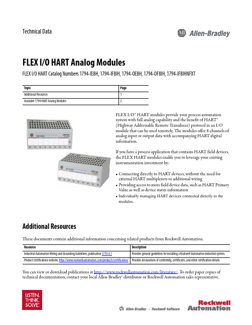
Technical DataFLEX I/O HART Analog ModulesFLEX I/O HART Catalog Numbers 1794-IE8H, 1794-IF8IH, 1794-OE8H, 1794-OF8IH, 1794-IF8IHNFXTFLEX I/O™ HART modules provide your process automation system with full analog capability and the benefit of HART® (Highway Addressable Remote T ransducer) protocol in an I/O module that can be used remotely. The modules offer 8 channels of analog input or output data with accompanying HART digital information.If you have a process application that contains HART field devices, the FLEX HART modules enable you to leverage your existing instrumentation investment by:•Connecting directly to HART devices, without the need for external HART multiplexers or additional wiring•Providing access to more field device data, such as HART Primary Value as well as device status information•Individually managing HART devices connected directly to the modules .Additional ResourcesThese documents contain additional information concerning related products from Rockwell Automation.Y ou can view or download publications at /literature/. T o order paper copies of technical documentation, contact your local Allen-Bradley® distributor or Rockwell Automation sales representative.TopicPage Additional Resources1Available 1794 HART Analog Modules2ResourceDescriptionIndustrial Automation Wiring and Grounding Guidelines, publication 1770-4.1Provides general guidelines for installing a Rockwell Automation industrial system.Product Certifications website,/products/certification/Provides declarations of conformity, certificates, and other certification details.FLEX I/O HART Analog ModulesAvailable 1794 HART Analog ModulesHART is a field proven, global industry standard with unmatched range of products and worldwide support. Using Cyclic EDT, a mechanism is used to transfer the large amount of HART data between the module and the adapter and via an additional connection to the controller for use by the end application.FLEX I/O Module TypesType Description1794-IE8H 1794-OE8H •Conformal coated modules•Provide connection to HART smart field devices such that valuable information is obtainable to help plants:–Avoid process disruptions–Improve process operations–Better manage plant assets•Customers want to bring HART data into their controllers, HMI and asset management software. These modules address this need.•These modules provide analog and HART in one module. No need for separate analog module nor separate wiring as with traditional solutions.•HART commands can be sent/received embedded in unscheduled CIP messages by a controller, HMI or third party software on ControlNet or EtherNet/IP.•Compatible with FDT-based HART device management software through use of DTMs.1794-IF8IH 1794-OF8IH 1794-IF8IHNFXT •Can be User configured to support a variety of applications including digital HART sensors and/or traditional analog sensors requiring high channel to channel isolation.•Support 8 channels of current input in multiple ranges and multiple formats. The module provides “120 VAC continuous” isolation between channels. The module will draw most of its power from a user provided external 24 VDC power supply.•RoHS compliance and extended temperature operation, a change in input filter characteristics and a number of functional changes from the the existing 1794-IF8IH module to create the 1794-IF8IHNFXT module.FLEX I/O ModulesModule Type Catalog Number PageHART Analog1794-IE8H1794-OE8H31794-IF8IH1794-OF8IH1794-IF8IHNFXT52Rockwell Automation Publication 1794-TD018A-EN-E - November 2013FLEX I/O HART Analog Modules 1794-IE8H, 1794-OE8HFLEX I/O HART Enabled Analog 8 Input Module, HART Enabled Analog 8 Output Module.Technical SpecificationsAttribute1794-IE8H1794-OE8HNumber of inputs/outputs8 single ended, non-isolated, non dedicated HART modemper channel 8 dual ended output channels referenced over sense resistors to a single commonConformally coated YesIndicators8 red fault indicators8 yellow HART communication indicators1 green power indicatorFlexbus current, 5V DC80 mAPower supplyVoltage: Current:24V DC nominal, 19.2…31.2V DC (includes 5% AC ripple) 190 mA @ 24V DCFunctional data range>17V @ 22 mA>23V @ 0 mA >15V @ 22 mA >22V @ 0 mAResolution16 bits13 bits,12.5 bits 4…20mAData format2’s complement, mA or integer values, % of full scaleConversion type Successive approximation Sigma deltaConversion rate10 ms (50 Hz) / 8.33 ms (60 Hz)10 ms all channelsStep response to 99% of full scale80 ms18 msAll channels updated to FLEX Bus≤ 10 ms≤ 13 msModule to appear approximate best/worst update time200 μs / 1600 μsTemperature drift50 ppm/C (K)80 ppm/C (K)Absolute accuracy(1)0.1% Full Scale @ 20 °C (68 °F)Acuracy drift with temperature(1)0.05% full scale for 0...55 °C (32...131 °F)0.010% full scale for 0...55 °C (32...131 °F)Calibration Factory calibratedIsolation voltage50V (continuous), Basic insulation type between field side and systemTested @ 850V AC for 1 s with no isolation between individual channelsPower dissipation, max ************************Thermal dissipation 13.5BTU/**********20.8BTU/**********Recommended terminal base1794-TB3G or 1794-TB3GSTerminal base screw torque0.8 Nm (7 lb-in.)Wire type ShieldedWire size Determined by installed terminal baseCompatibility HART 5Device supported 2 wiresNorth American temperature code T4AIEC temperature code T4Rockwell Automation Publication 1794-TD018A-EN-E - November 20133FLEX I/O HART Analog ModulesEnclosure type rating None (Open style)Dimensions, approx. (HxWxD)46 x 94 x 53 mm (1.8 x 3.7 x 2.1 in.)Publication, Installation Instructions1794-IN1081794-IN109 (1)Includes offset, gain, nonlinearity, and repeatability error terms.Environmental SpecificationsAttribute1794-IE8H1794-OE8H Temperature, operating IEC 60068-2-1 (Test Ad, Operating Cold),IEC 60068-2-2 (Test Bd, Operating Dry Heat),IEC 60068-2-14 (Test Nb, Operating Thermal Shock):-20…55 °C (-4…131 °F)Temperature, nonoperating IEC 60068-2-1 (Test Ab, Unpackaged Nonoperating Cold),IEC 60068-2-2 (Test Bb, Unpackaged Nonoperating Dry Heat),IEC 60068-2-14 (Test Na, Unpackaged Nonoperating Thermal Shock):-40…85 °C (-40…185 °F)Relative humidity IEC 60068-2-30 (Test Db, Unpackaged Nonoperating Damp Heat):5…95% noncondensingVibration IEC 60068-2-6 (Test Fc, Operating):2 g @ 10…500 HzShock, operating IEC 60068-2-27 (Test Ea, Unpackaged Shock):15 gShock, nonoperating IEC 60068-2-27 (Test Ea, Unpackaged Shock):15 gEmissions CISPR 11: Group 1, Class A (with appropriate enclosure)ESD immunity IEC 61000-4-2:6kV contact discharges8 kV air dischargesRadiated RF immunity IEC 61000-4-3:10V/m with 1 kHz sine-wave 80% AM from 80...2500 MHz1V/m with 1 kHz sine-wave 80% AM from 2500...2700 MHzEFT/B immunity IEC 61000-4-4:±2 kV @ 5 kHz on power ports±2 kV @ 5 kHz on signal portsSurge transient immunity IEC 61000-4-5:±1 kV line-line(DM) and ±2 kV line-earth(CM) on power ports±2 kV line-earth(CM) on shielded portsConducted RF immunity IEC 61000-4-6:10V rms with 1 kHz sine-wave 80% AM from 10 kHz…80 MHz IEC 61000-4-6:10V rms with 1 kHz sine-wave 80% AM from 150 kHz…80 MHzTechnical SpecificationsAttribute1794-IE8H1794-OE8H4Rockwell Automation Publication 1794-TD018A-EN-E - November 2013Rockwell Automation Publication 1794-TD018A-EN-E - November 20135FLEX I/O HART Analog Modules1794-IF8IH, 1794-OF8IH, 1794-IF8IHNFXTFLEX I/O HART Enabeld Isolated Analog 4 Input Module, FLEX I/O HART Enabled Isolated Analog 4 Input Extreme Temperature ModuleCertificationsCertification (1)(When marked on product)(1)See the Product Certification link at /products/certification/ for Declaration of Conformity, Certificates, and other certification details.1794-IE8H1794-OE8Hc-UL-us UL Listed Industrial Control Equipment, certified for US and Canada. See UL File E65584.UL Listed for Class I, Division 2 Group A,B,C,D Hazardous Locations, certified for U.S. and Canada. See UL File E194810.CEEuropean Union 2004/108/IEC EMC Directive, compliant with:EN 61326-1; Meas./Control/Lab., Industrial Requirements EN 61000-6-2; Industrial Immunity EN 61000-6-4; Industrial EmissionsEN 61131-2; Programmable Controllers (Clause 8, Zone A & B)C-Tick Australian Radiocommunications Act, compliant with:AS/NZS CISPR 11; Industrial EmissionsExEuropean Union 94/9/EC ATEX Directive, compliant with:EN 60079-15; Potentially Explosive Atmospheres, Protection "n"EN 60079-0; General Requirements II 3 G Ex nA IIC T4 XKCKorean Registration of Broadcasting and Communications Equipment, compliant with:Article 58-2 of Radio Waves Act, Clause 3Technical SpecificationsAttribute1794-IF8IH 1794-OF8IH1794-IF8IHNFXTNumber of inputs/outputs 8 single-ended isolated Indicators 1 red/green power/status indicator Flexbus current, 5V DC 80 mAPower supply Voltage Current 24V DC nominal, 19.2…31.2V DC (includes 5% AC ripple)190 mA @ 24V DC24V DC nominal, 19.2…31.2V DC (includes 5% AC ripple)450 mA @ 24V DC24V DC nominal, 19.2…31.2V DC (includes 5% AC ripple)190 mA @ 24V DCCurrent terminal4…20 mA (user configurable)0…20 mA (user configurable)0 mA output until product is configured Resolution16 bits - unipolar15 bits plus sign - bipolar 0.320 μA/cnt unipolar 0.640 μA/cnt bipolar 16 bits - unipolar 0.305 μA/cnt unipolar16 bits - unipolar 0.3052 μA/cnt unipolar 0.6104 μA/cnt bipolarData formatEngineering Units (2)Percent of Full Scale RAW/Proportional Count Conversion type Sigma Delta16 bits digital to analog converter Sigma DeltaConversion rate Refer to update rate table in publication, 1794-IN11510 msRefer to update rate table in publication,1794-IN134Resistance249 Ω ± 1%0 … 750 Ω standard249 Ω ± 1%6Rockwell Automation Publication 1794-TD018A-EN-E - November 2013FLEX I/O HART Analog ModulesNormal mode rejection ratio - voltage or current terminal>70 dB @ 50/60 Hz (4.17 Hz ADC conversion rate)>65 dB @ 50/60 Hz (10.0 Hz ADC conversion rate)>75 dB @ 50 Hz (16.7 Hz ADC conversion rate)>85 dB @ 60 Hz (19.6 Hz ADC conversion rate)>70 dB @ 50/60 Hz (4.17 Hz ADC conversion rate)>65 dB @ 50/60 Hz (10.0 Hz ADC conversion rate)>75 dB @ 50 Hz (16.7 Hz ADC conversion rate)>70 dB @ 60 Hz (19.6 Hz ADC conversion rate)Common mode rejection ratio >60 dB @ 50 Hz >60 dB @ 60 HzStep response to 99% full scale to current terminal4.17 Hz conversion rate = 480 ms 10.0 Hz conversion rate = 200 ms 16.7 Hz conversion rate = 120 ms 19.6 Hz conversion rate = 101 ms 62 Hz conversion rate = 32 ms 470 Hz conversion rate = 4 ms -4.17 Hz conversion rate = 480 ms 10.0 Hz conversion rate = 200 ms 16.7 Hz conversion rate = 120 ms 19.6 Hz conversion rate = 101 ms 62 Hz conversion rate = 32 ms 123 Hz conversion rate = 17 ms 242 Hz conversion rate = 14 ms Absolute accuracy (1)0.1% full scale @ 25 °C ± 0.1% full scale @ 25 °C ± 0.35% full scale @ 0…55 °C 0.1% full scale @ 25 °C Accuracy drift with temperature (1)0.4% full scale for 0…55 °C 0.008 % /°C0.0038 % full scale/°C0.55% full scale for -25…70 °CCalibration Factory calibrated.Maximum overload 32 mA continuousIsolation voltage120V (continuous), Basic Insulation TypeType tested @ 1000V AC for 60 s, between User power to system, channel to system, and channel to channel 120V (continuous), Basic Insulation TypeType tested @ 1500V AC for 60 s, between channel to power, channel to system, and power to system, and channel to channel. Power dissipation, max **********10.8 W @ 24V DC ************Thermal dissipation 20.5BTU/**********36.8 BTU/hr @ 24V DC 16.4BTU/**********Recommended terminal base 1794-TB3, 1794-TB3S Terminal screw torque 0.8 Nm (7 lb-in.)Wire type ShieldedWire size Determined by installed terminal base Compatibility HART 5HART 5, 6, 7Device supported 2, 3, 4 wires North American temperature code T4T5IEC temperature code T4Enclosure type rating None (open-style)Dimensions, approx. (HxWxD)with module installed in base 94 x 94 x 66 mm (3.7 x 3.7 x 2.6 in.)Publication,Installation Instructions1794-IN1151794-IN1201794-IN134(1)Includes offset, gain, non-linearity and repeatability error terms.(2)Engineering Units apply to HART data only.Technical SpecificationsAttribute1794-IF8IH1794-OF8IH1794-IF8IHNFXTFLEX I/O HART Analog ModulesEnvironmental SpecificationsAttribute1794-IF8IH1794-OF8IH1794-IF8IHNFXTTemperature, operating IEC 60068-2-1 (Test Ad, Operating Cold),IEC 60068-2-2 (Test Bd, Operating Dry Heat),IEC 60068-2-14 (Test Nb, Operating Thermal Shock):0…55 °C (32…131 °F) -25…70 °C (-13…158 °F)Temperature, nonoperating IEC 60068-2-1 (Test Ab, Unpackaged Nonoperating Cold),IEC 60068-2-2 (Test Bb, Unpackaged Nonoperating Dry Heat),IEC 60068-2-14 (Test Na, Unpackaged Nonoperating Thermal Shock):-40…85 °C (-40…185 °F)Relative humidity IEC 60068-2-30 (Test Db, Unpackaged Nonoperating Damp Heat):5…95 % noncondensingVibration IEC 60068-2-6 (Test Fc, Operating):5 g @ 10…500 HzShock, operating IEC 60068-2-27 (Test Ea, Unpackaged Shock) :20 g30 gShock, nonoperating IEC 60068-2-27 (Test Ea, Unpackaged Shock):25 g50 gEmissions CISPR 11: Group 1, Class AESD immunity IEC 61000-4-2:6 kV contact discharges8 kV air dischargesRadiated RF immunity IEC 61000-4-3:10V/m with 1kHz sine-wave 80% AM from 80… 2000 MHz10V/m with 200Hz 50% Pulse 100% AM @ 900 MHz10V/m with 200Hz 50% Pulse 100% AM @ 1890 MHz3V/m with 1kHz sine-wave 80% AM from 2000…2700 MHz IEC 61000-4-3:10V/m with 1kHz sine-wave 80% AM from 80… 2000 MHz 10V/m with 200Hz 50% Pulse 100% AM @ 900 MHz10V/m with 200Hz 50% Pulse 100% AM @ 1890 MHz10V/m with 1kHz sine-wave 80% AM from 2000…2700 MHzEFT/B immunity IEC 61000-4-4:±3 kV @ 5 kHz on signal ports IEC 61000-4-4:±3 kV @ 5 kHz on signal ports ±3 kV @ 5 kHz on power portsSurge transient immunity IEC 61000-4-5:±2 kV line-earth(CM) on shielded ports IEC 61000-4-5:±1 kV line-line(DM) and ±2 kV line-earth(CM) on power ports ±2 kV line-earth(CM) on shielded portsConducted RF immunity IEC 61000-4-6:10V rms with 1 kHz sine-wave 80% AM from 150 kHz…80 MHzCertificationsCertification(1)(When marked on product)1794-IF8IH1794-OF8IH1794-IF8IHNFXTc-UL-us UL Listed Industrial Control Equipment, certified for US and Canada. See UL File E65584.UL Listed for Class I, Division 2 Group A,B,C,D Hazardous Locations, certified for U.S. and Canada. See UL File E194810.CE European Union 2004/108/IEC EMC Directive, compliant with:EN 61326-1; Meas./Control/Lab., Industrial RequirementsEN 61000-6-2; Industrial ImmunityEN 61000-6-4; Industrial EmissionsEN 61131-2; Programmable Controllers (Clause 8, Zone A & B)C-Tick Australian Radiocommunications Act, compliant with:AS/NZS CISPR 11; Industrial EmissionsRockwell Automation Publication 1794-TD018A-EN-E - November 201378Rockwell Automation Publication 1794-TD018A-EN-E - November 2013FLEX I/O HART Analog ModulesExEuropean Union 94/9/EC ATEX Directive, compliant with:EN 60079-15; Potentially Explosive Atmospheres, Protection "n"EN 60079-0; General Requirements II 3 G Ex nA IIC T4 Gc TÜV -TÜV Certified for Functional Safety (2): Capable of SIL 2 KCKorean Registration of Broadcasting and Communications Equipment, compliant with:Article 58-2 of Radio Waves Act, Clause 3-(1)See the Product Certification link at /products/certification/ for Declaration of Conformity, Certificates, and other certification details.(2)When used with specified firmware revisions.CertificationsCertification (1)(When marked on product)1794-IF8IH1794-OF8IH1794-IF8IHNFXTFLEX I/O HART Analog Modules Notes:Rockwell Automation Publication 1794-TD018A-EN-E - November 20139Allen-Bradley, FLEX I/O, RSLogix 5000, Rockwell Software, Rockwell Automation, and LISTEN. THINK. SOLVE are trademarks of Rockwell Automation, Inc.T rademarks not belonging to Rockwell Automation are property of their respective companies.Publication 1794-TD018A-EN-E - November 2013Copyright © 2013 Rockwell Automation, Inc. All rights reserved.Important User InformationSolid-state equipment has operational characteristics differing from those of electromechanical equipment. SafetyGuidelines for the Application, Installation and Maintenance of Solid State Controls (publication SGI-1.1 available from your local Rockwell Automation sales office or online at /literature/) describes some important differences between solid-state equipment and hard-wired electromechanical devices. Because of this difference, and also because of the wide variety of uses for solid-state equipment, all persons responsible for applying this equipment must satisfy themselves that each intended application of this equipment is acceptable.In no event will Rockwell Automation, Inc. be responsible or liable for indirect or consequential damages resulting from the use or application of this equipment.The examples and diagrams in this publication are included solely for illustrative purposes. Because of the many variables and requirements associated with any particular installation, Rockwell Automation, Inc. cannot assume responsibility or liability for actual use based on the examples and diagrams.No patent liability is assumed by Rockwell Automation, Inc. with respect to use of information, circuits, equipment, or software described in this manual.Reproduction of the contents of this manual, in whole or in part, without written permission of Rockwell Automation, Inc., is prohibited.Documentation FeedbackY our comments will help us serve your documentation needs better. If you have any suggestions on how to improve this document, complete this form, publication RA-DU002, available at /literature/.Rockwell Otomasyon Ticaret A.Ş., Kar Plaza İş Merkezi E Blok Kat:6 34752 İçerenköy, İstanbul, T el: +90 (216) 5698400。
罗克韦尔自动化 信任 40 通道 120 Vdc 数字输入 FTA 用户手册说明书
PD-T8821 TrustedTrusted 40 Channel 120 Vdc Digital Input FTA Product OverviewThe Trusted® 40 Channel 120 Vdc Digital Input Field Termination Assembly (FTA) T8821 is designed to act as the main interface between a field device generating a digital signal and the Trusted TMR 120 Vdc Digital Input Module T8423.Features:•40 input channels per FTA.•Industry standard field device connections (2-wire).•Standard DIN rail compatibility.•Simple installation and connection.•120 Vdc operation.•SmartSlot connection for ‘one to many’ hot replacement of input modules.•Fused field power supply per channel.•On-board Light Emitting Diode (LED) indication of field power supply integrity.Trusted PD-T8821Page intentionally left blankPREFACEIn no event will Rockwell Automation be responsible or liable for indirect or consequential damages resulting from the use or application of this equipment. The examples given in this manual are included solely for illustrative purposes. Because of the many variables and requirements related to any particular installation, Rockwell Automation does not assume responsibility or reliability for actual use based on the examples and diagrams.No patent liability is assumed by Rockwell Automation, with respect to use of information, circuits, equipment, or software described in this manual.All trademarks are acknowledged.DISCLAIMERIt is not intended that the information in this publication covers every possible detail about the construction, operation, or maintenance of a control system installation. You should also refer to your own local (or supplied) system safety manual, installation and operator/maintenance manuals.REVISION AND UPDATING POLICYThis document is based on information available at the time of its publication. The document contents are subject to change from time to time. The latest versions of the manuals are available at the Rockwell Automation Literature Library under "Product Information" information "Critical Process Control & Safety Systems".TRUSTED RELEASEThis technical manual applies to Trusted Release: 3.6.1.LATEST PRODUCT INFORMATIONFor the latest information about this product review the Product Notifications and Technical Notes issued by technical support. Product Notifications and product support are available at the Rockwell Automation Support Centre atAt the Search Knowledgebase tab select the option "By Product" then scroll down and select the Trusted product.Some of the Answer ID’s in the Knowledge Base require a TechConnect Support Contract. For more information about TechConnect Support Contract Access Level and Features please click on the following link:https:///app/answers/detail/a_id/50871This will get you to the login page where you must enter your login details.IMPORTANT A login is required to access the link. If you do not have an account then you can create one using the "Sign Up" link at the top right of the web page.DOCUMENTATION FEEDBACKYour comments help us to write better user documentation. If you discover an error, or have a suggestion on how to make this publication better, send your comment to our technical support group at SCOPEThis manual specifies the maintenance requirements and describes the procedures to assist troubleshooting and maintenance of a Trusted system. WHO SHOULD USE THIS MANUALThis manual is for plant maintenance personnel who are experienced in the operation and maintenance of electronic equipment and are trained to work with safety systems. SYMBOLSIn this manual we will use these notices to tell you about safety considerations.SHOCK HAZARD: Identifies an electrical shock hazard. If a warning label is fitted, it can be on or inside the equipment.WARNING: Identifies information about practices or circumstances that can cause an explosion in a hazardous environment, which can cause injury or death, property damage or economic loss.ATTENTION: Identifies information about practices or circumstances that can cause injury or death.CAUTION: Identifies information about practices or circumstances that can cause property damage or economic loss.BURN HAZARD: Identifies where a surface can reach dangerous temperatures. If a warning label is fitted, it can be on or inside the equipment.This symbol identifies items which must be thought about and put in place when designing and assembling a Trusted controller for use in a Safety Instrumented Function (SIF). It appears extensively in the Trusted Safety Manual.IMPORTANTIdentifies information that is critical for successful application and understanding of the product.NOTE Provides key information about the product or service.TIP Tips give helpful information about using or setting up the equipment.WARNINGS AND CAUTIONSWARNING: EXPLOSION RISKDo not connect or disconnect equipment while the circuit is live or unless the area is known to be free of ignitable concentrations or equivalentAVERTISSEMENT - RISQUE D’EXPLOSIONNe pas connecter ou déconnecter l’équipement alors qu’il est sous tension, sauf si l’environnement est exempt de concentrations inflammables ou équivalenteMAINTENANCEMaintenance must be carried out only by qualified personnel. Failure to follow these instructions may result in personal injury.CAUTION: RADIO FREQUENCY INTERFERENCEMost electronic equipment is influenced by Radio Frequency Interference. Caution should be exercised with regard to the use of portable communications equipment around such equipment. Signs should be posted in the vicinity of the equipment cautioning against the use of portable communications equipment.CAUTION:The module PCBs contains static sensitive components. Static handling precautions must be observed. DO NOT touch exposed connector pins or attempt to dismantle a module.ISSUE RECORDIssue Date Comments5 Sep 05 Format6 Feb 08 Voltage warning7 Jun 16 Rebranded and updated to incorporate IEEE standards with correction oftypographical errors and also standardise the Relative Humidity Rangeand Operating Temperature statements in the Specification Section.Page intentionally left blankTrusted 40 Channel 120Vdc Digital Input FTA Table of Contents Table of Contents1.Description (3)2.Installation (5)3.Associated Cable Selection (7)4.Assembly Pinout Connections (9)4.1. PWR TB Connections (9)4.2. TB3 (Auxiliary Input) (9)4.3. TB2 (Field Terminals) (9)4.4. SK1 and SK2 (11)5.Specifications (14)Table of Contents Trusted 40 Channel 120Vdc Digital Input FTAPage intentionally left blank1.DescriptionFigure 1 T8821 LayoutThe Trusted 40 Channel 120 Vdc Digital Input FTA T8821 provides termination for a maximum of 40 input channels from various types of field devices which generate a digital input. Figure 2 below shows the configuration of a single channel.Figure 2 Single Channel SchematicThe supply for the field is derived from dual 120 Vdc feeds which are ‘commoned’ via diodes on the FTA. Indication of the presence of the power supply is provided by a green LED. The supply is then fed to each channel.The supply voltage to the field is fed via the 50 mA fuse. This effectively limits the current in the field loop. The incoming signal (digital) from the field device is fed directly to the digital input module. Line monitoring components (if required) provide the necessary thresholds used by the input module to detect the field loop/device status, i.e. open/short circuit, alarm etc.The cable linking the 40 channels on the input module to the FTA is terminated at the96-way socket SK1. SmartSlot (Version 1) signals from the module are connected to SK1. The SmartSlot connector is SK2 and is also a 96-way socket. This connector is not used where SmartSlot Version 2 is employed within the Trusted System. The dual dc field power supplies are connected to the FTA via a 5-way terminal block PWR TB. The input signals from thefield (40-off) are connected by 2-wire arrangements terminated on 12-off 3-way terminal blocks and 2-off 2-way.2.InstallationTrusted 40 Channel 120 Vdc Digital Input FTA T8821 is designed to be mounted on either of the TS32 or TS35 DIN rails in the horizontal or vertical positions as required.Page intentionally left blank3.Associated Cable SelectionRefer to the product descriptions detailed below: PD-TC000 Trusted Power CablesPD-TC200 Trusted I/O Companion Slot Cables PD-TC500 Trusted I/O SmartSlot Cables Version 2Page intentionally left blank4.Assembly Pinout Connections 4.1.PWR TB ConnectionsPin Service1 120 V-A2 120 V-B3 0 V4 0 V5 120 V(auxiliary supply for use when required) Table 1 PWR TB Connections4.2.TB3 (Auxiliary Input)Pin Service1 Chan 0 (not configured)2 Chan 41(not configured)Table 2 TB3 (Auxiliary Input) Connections4.3.TB2 (Field Terminals)Pin Service Pin Service1 Chan 1 120 Vdc field supply2 Chan 1 signal from field3 Chan 2 120 Vdc field supply4 Chan 2 signal from field5 Chan 3 120 Vdc field supply6 Chan 3 signal from field7 Chan 4 120 Vdc field supply 8 Chan 4 signal from field9 Chan 5 120 Vdc field supply 10 Chan 5 signal from field11 Chan 6 120 Vdc field supply 12 Chan 6 signal from field 13 Chan 7 120 Vdc field supply 14 Chan 7 signal from field 15 Chan 8 120 Vdc field supply 16 Chan 8 signal from field 17 Chan 9 120 Vdc field supply 18 Chan 9 signal from field 19 Chan 10 120 Vdc field supply 20 Chan 10 signal from field 21 Chan 11 120 Vdc field supply 22 Chan 11 signal from field 23 Chan 12 120 Vdc field supply 24 Chan 12 signal from field 25 Chan 13 120 Vdc field supply 26 Chan 13 signal from field 27 Chan 14 120 Vdc field supply 28 Chan 14 signal from field 29 Chan 15 120 Vdc field supply 30 Chan 15 signal from field 31 Chan 16 120 Vdc field supply 32 Chan 16 signal from field 33 Chan 17 120 Vdc field supply 34 Chan 17 signal from field 35 Chan 18 120 Vdc field supply 36 Chan 18 signal from field 37 Chan 19 120 Vdc field supply 38 Chan 19 signal from field 39 Chan 20 120 Vdc field supply 40 Chan 20 signal from field 41 Chan 21 120 Vdc field supply 42 Chan 21 signal from field 43 Chan 22 120 Vdc field supply 44 Chan 22 signal from field 45 Chan 23 120 Vdc field supply 46 Chan 23 signal from field 47 Chan 24 120 Vdc field supply 48 Chan 24 signal from field 49 Chan 25 120 Vdc field supply 50 Chan 25 signal from field 51 Chan 26 120 Vdc field supply 52 Chan 26 signal from field 53 Chan 27 120 Vdc field supply 54 Chan 27 signal from field 55 Chan 28 120 Vdc field supply 56 Chan 28 signal from field 57 Chan 29 120 Vdc field supply 58 Chan 29 signal from field59 Chan 30 120 Vdc field supply 60 Chan 30 signal from field61 Chan 31 120 Vdc field supply 62 Chan 31 signal from field63 Chan 32 120 Vdc field supply 64 Chan 32 signal from field65 Chan 33 120 Vdc field supply 66 Chan 33 signal from field67 Chan 34 120 Vdc field supply 68 Chan 34 signal from field69 Chan 35 120 Vdc field supply 70 Chan 35 signal from field71 Chan 36 120 Vdc field supply 72 Chan 36 signal from field73 Chan 37 120 Vdc field supply 74 Chan 37 signal from field75 Chan 38 120 Vdc field supply 76 Chan 38 signal from field77 Chan 39 120 Vdc field supply 78 Chan 39 signal from field79 Chan 40 120 Vdc field supply 80 Chan 40 signal from fieldTable 3 TB2 Field Terminals4.4.SK1 and SK2C B A1 SmartSlot Link C SmartSlot Link B SmartSlot Link A23 Chan 28 (+) Chan 14 (+) Chan 0 (+)4 Chan 28 (+) Chan 14 (+) Chan 0 (+)5 Chan 29 (+) Chan 15 (+) Chan 1 (+)6 Chan 29 (+) Chan 15 (+) Chan 1 (+)7 Chan 30 (+) Chan 16 (+) Chan 2 (+)8 Chan 30(+) Chan 16 (+) Chan 2 (+)9 0 V 0 V 0 V10 Chan 31 (+) Chan 17 (+) Chan 3 (+)C B A11 Chan 31 (+) Chan 17 (+) Chan 3 (+)12 Chan 32 (+) Chan 18 (+) Chan 4 (+)13 Chan 32 (+) Chan 18 (+) Chan 4 (+)14 Chan 33 (+) Chan 19 (+) Chan 5 (+)15 Chan 33 (+) Chan 19 (+) Chan 5 (+)16 Chan 34 (+) Chan 20 (+) Chan 6 (+)17 Chan 34 (+) Chan 20 (+) Chan 6 (+)18 Chan 35 (+) Chan 21 (+) Chan 7 (+)19 Chan35 (+) Chan 21 (+) Chan 7 (+)20 0 V 0 V 0 V21 Chan 36 (+) Chan 22 (+) Chan 8 (+)22 Chan 36 (+) Chan 22 (+) Chan 8 (+)23 Chan 37 (+) Chan 23 (+) Chan 9 (+)24 Chan 37 (+) Chan 23 (+) Chan 9 (+)25 Chan 38 (+) Chan 24 (+) Chan 10 (+)26 Chan 38 (+) Chan 24 (+) Chan 10 (+)27 Chan 39 (+) Chan 25 (+) Chan 11 (+)28 Chan 39 (+) Chan 25 (+) Chan 11 (+)29 Chan 40 (+) Chan 26 (+) Chan 12 (+)30 Chan 40 (+) Chan 26 (+) Chan 12 (+)31 Chan 41 (+) Chan 27 (+) Chan 13 (+)32 Chan 41 (+) Chan 27 (+) Chan 13 (+)Table 4 SK1 and SK2 ConnectionsTrusted 40 Channel 120Vdc Digital Input FTA 4. Assembly Pinout ConnectionsPage intentionally left blankTrusted 40 Channel 120Vdc Digital Input FTA 5. Specifications 5.SpecificationsVoltage Range 90 Vdc to 140 VdcFuses 40-off 50 mAMaximum Current (Field Supply) 1 mAPower Consumption (Field Supply) 0.125 WOperating Temperature 0 °C to +60 °C (+32 °F to +140 °F)Non-operating Temperature -25 °C to +70 °C (-13 °F to +158 °F)10 % – 95 %, non-condensingRelative Humidity range(operating, storage and transport)Environmental Specifications Refer to Document 552517DimensionsHeight111 mm (4.4 in)Width335 mm (13.2 in)Depth51 mm (2 in)Weight 900 g (2 lb)。
- 1、下载文档前请自行甄别文档内容的完整性,平台不提供额外的编辑、内容补充、找答案等附加服务。
- 2、"仅部分预览"的文档,不可在线预览部分如存在完整性等问题,可反馈申请退款(可完整预览的文档不适用该条件!)。
- 3、如文档侵犯您的权益,请联系客服反馈,我们会尽快为您处理(人工客服工作时间:9:00-18:30)。
/sensors-switches/rfid
高频 13.56 MHZ ICODE RFID 解决方案
EtherNet/IP 接口模块 RFID 端口 输入
1
1
2
1
2
2
输出
1 1 -
产品目录号
56RF-IN-IPS12 56RF-IN-IPD22 56RF-IN-IPD22A
40 x 40
85
56RF-TR-4040
圆柱形
M30
35
60
56RF-TR-M30
圆柱形 18
M18
30
56RF-TR-M18
* 注:大多数常见应用项目的最佳距离。直径 50 mm 标签的参考范围。 ** 在理想条件下使用 50 mm 标签时,仅供参考。
标签
外形
圆形
类型
SLI
SLI-L SLI-S 圆形 - 抗冲击性强 (极为耐用) SLI 圆形 - 在金属上安装 SLI 圆形 - FRAM
889D-F5FC-J 889D-R5FC-J 889D-M5FC-J 889D-E5FC-J
6 本章节将帮您确定适用于您应用项目的推荐收发器。如果是高速应用项目,最好能选择具备最大天线范围的最大型收 发器。这样标签在区域内执行读 / 写功能的时间最长。而且发生标签错位时,也能提供帮助。如果执行所有读 / 写功能 时您的标签将会静止,并且发生标签错位也没有影响,则可以使用较小的收发器。
7 收发器越大,天线覆盖区域也越大。这通常与标签的物理尺寸有关。对于较大的收发器,建议使用较大的标签。相 反,较小的收发器则可以使用物理尺寸较小的标签。
手持接口
用于手动读 / 写标签的附件。
• Microsoft® Windows® CE 5.0 • 通过无线、Bluetooth®、
CompactFlash、USB 或 RS-232 传送数据 • IP65 防护等级 - 防尘,防雨 • 彩色触摸显示屏 • 与所有 Allen-Bradley® ICODE RFID 标签兼容
产品目录号
57RF-HH-56US1
57RF-HH-56US2
57RF-HH-56IN 57RF-HH-56BAT 57RF-HH-56CA
1784-CF64 1784-CF128
存储容量
128 字节 64 字节 256 字节 128 字节 128 字节
2K 字节
128 字节 128 字节 128 字节
收发器:M18、M30
收发器:正方形 (40 mm x 40 mm)
标签尺寸:10 – 30 mm
标签尺寸:30 – 50 mm
快速
收发器:矩形 (80 mm x 90 mm) 标签尺寸:50 – 86 mm
1 高频 RFID 产品通常用于在工业应用项目中追踪制造过程中的产品。收发器到标签之间的距离通常小于 8 in. (200 mm)。 ICODE 技术优势明显,因为有众多供应商能提供物理封装形式丰富多样的各类标签。
出版物 RFID-BR001A-ZH-P – 2011 年 9 月
©2011 罗克韦尔自动化公司版权所有。保留所有权利。美国印刷。
工业无线电频率识别 (RFID)
带有 EtherNet/IP 接口的高频 13.56 MHz ICODE RFID
工业无线电频率识别 (RFID) 系统坚固而且可靠,可用于追踪和记 录制造过程中的产品。工业 RFID 系统与用于同类低端应用的条 形码系统不同,其设计可以承受严苛的工业环境。此外,可重复
手持接口
说明
RFID 手持接口, 52 键键盘, 带方向键
RFID 手持接口, 45 键键盘
产品目录号
57RF-HH-56A 57RF-HH-56B
收发器
尺寸 (mm)
建议 检测 距离
(mm)*
最大 检测 距离
(mm)**
产品 目录号
矩形
80 x 90
100
168
56RF-TR-8090
正方形 50
• 使用集成架构构建器配置并生成基于 NetLinx 的网络的物料 清单
• 凭借易于使用的 ProposalWorks 界面,您可以快速确定切实需 要的 Allen-Bradley® 产品和服务,并获得最新的价格表
• 该软件能自动选择相应的信息文档、图片等
Allen-Bradley、CompactLogix、FactoryTalk、Integrated Architecture、Kinetix、PanelView、PowerFlex、ProposalWorks、Rockwell Automation 和 Stratix 是罗克韦尔自动化有限公司的商标。 其他所有商标和注册商标均为其各自所有者的资产。
2 应用程序可以直接将数据存储在标签上,或在服务器中将 UID (唯一标识符) 与数据链接起来,从而借由标签追踪过程。 在高速应用项目中 (> 1.5 m/s),建议仅将 UID 读取到 PLC 中。如果在多台彼此间没有通信的机器上使用标签,则通常会 将数据存储在标签上。通过将所有数据存储在标签上,在机器循环上电之后仍能保存数据。
应用领域
汽车
包装
AGV
制药
标签能识别车门的颜色、 类型和存储位置。
在整个生产过程中追踪 产品。
将标签嵌入地面中,引导建 筑物内的无人驾驶车。
在加工过程中追踪托盘内的 药品,实现出色的可追踪 性、精确性和品质担保。
如要了解更多... 请访问以下网址观看此视频和其它应用视频:/sensors-switches/rfid 制造应用 - 每件工具、每个人和每台机器都有一个用于验证和统计节
达到 128 字节
4 SLI 标签 RFID HF 应用项目中 最常用的类型
3
达到 2k 字节 5
FRAM 标签
6
标签 速度快 vs 慢/停止
7
检测 距离
4+ in. (100+ mm)
0 – 2 in. (0 – 50 mm)
2 – 4 in. (50 – 100 mm)
尺寸 (mm)
16 20 30 50 16 10
35
20 50
20 30 50
54 x 86 50 x 50
54 x 86
50 x 50
产品目录号
56RF-TG-16 56RF-TG-20 56RF-TG-30 56RF-TG-50 56RF-TG-16-64B 56RF-TG-10-256B
56RF-TG-35HIR
连接器类型
母头直型至公头直型 母头直型至公头直角型 母头直角型至公头直型 母头直角型至公头直角型
母头直型 母头直角型 公头直型 公头直角型
母头直型 母头直角型 公头直型 公头直角型
针数
4针 4针 4针
屏蔽
屏蔽 屏蔽
–
线规 (AWG)
22 22 18-22
产品目录号
889D-F5FCDM-J 889D-F5FCDE-J 889D-R5FCDM-J 889D-R5FCDE-J
• 使用我们的在线产品目录,您可以执行产品搜索、下载 PDF 格 式的资料、获取有用的安装提示等。
产品选型工具箱 集成架构构建器与 ProposalWorks™ • 我们提供了一系列功能强大的产品选型和系统配置工具,可帮
助用户选择和使用我们的产品。 请访问 /en/e-tools/
RFID 应用模拟器
RFID 应用模拟器可以: • 帮助设计和验证适合给定应用项目的最佳系统 • 显示收发器读 / 写区域的大小 • 提供标签穿越收发器区域并能交换需要收发的数据的最大速度
这款免费工具可在
ProposalWorks Create Proposals and Submittals
或 RFID 网站上找到:
• 通过为每件工具添加标签进 行库存管理
• 验证取用工具的用户
• 通过机器验证工具 • 读 / 写工具使用计数
• 在停机时间内安排工具维护 • 工具总使用次数存储在工具
RFID 标签上
高频 13.56 MHZ ICODE RFID 选型指南
闭环 生产步骤包含在制造设施中。
1 高频 HF 13.56 MHz ICODE
FRAM
标牌 (背面粘贴型) SLI
智能卡 SLI
正方形-耐高温型 (最高 240 °C ) SLI
手持附件
说明
国内标准单槽充电底座(带电缆)、 USB 电缆、触摸笔
国内标准壁式安装电源、串行电缆、 USB 电缆、触摸笔
国际标准电源套件、串行电缆、 USB 电缆、触摸笔 可充电电池组
15 ft 串行电缆、RS-232 64 MB CF 卡 128 MB CF 卡
3 我们的产品组合中有多种特殊标签可供选择: • 安全 • 隐私保护 • 极端温度环境
4 Allen Bradley 提供标牌、智能卡、圆形标签、方形标签以及适用于强冲击、金属安装等特殊应用场合的标签。SLI 标签 是高频工业 RFID 应用项目中最常用的标签。
5 对于机器彼此间没有通信,并且标签随机器全程移动的应用场合,这些大存储容量标签是最理想的选择。
本地经销商 • 请致电 1.800.223.3354 立即联系当地经销商。
/distributor/
RFID 网站 • 请浏览我们的网站 /
Sensors-Switches/RFID,了解我们的工业无线电频率识别(RFID) 产品能为您带来哪些帮助。收发器 / 标签选型指南将帮助您完 成订购
RFID 系统组件
接口模块
接收来自收发器的数据,并将数据发送 到 PLC。
• 采用 DLR 拓扑结构的 E/IP 嵌入式交 换机
• ISO 15693 / ISO 18000-3 M1 • 读 / 写 ICODE 标签 SLI / SL2 • 与所有 56RF 收发器兼容 • 本地 I/O