研工(KinSoon)23.6寸阳光下可视液晶屏KSN236SN01-A03规格书
Kingbright 蓝色LED灯的数据手册说明书
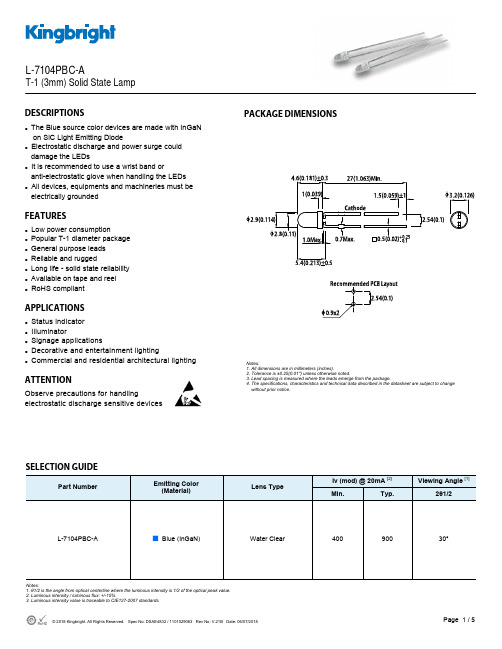
Part NumberEmitting Color (Material)Lens TypeIv (mcd) @ 20mA [2] Viewing Angle [1]Min. Typ. 2θ1/2L-7104PBC-A■ Blue (InGaN)Water Clear 400 30°900DESCRIPTIONSzThe Blue source color devices are made with InGaN on SiC Light Emitting Diodez Electrostatic discharge and power surge could damage the LEDsz It is recommended to use a wrist band oranti-electrostatic glove when handling the LEDs z All devices, equipments and machineries must be electrically groundedFEATURESzLow power consumptionz Popular T-1 diameter package z General purpose leads z Reliable and ruggedz Long life - solid state reliability z Available on tape and reel z RoHS compliantAPPLICATIONSz Status indicator z Illuminatorz Signage applicationsz Decorative and entertainment lightingzCommercial and residential architectural lightingATTENTIONObserve precautions for handlingelectrostatic discharge sensitive devicesPACKAGE DIMENSIONSL-7104PBC-AT-1 (3mm) Solid State LampSELECTION GUIDENotes:1. θ1/2 is the angle from optical centerline where the luminous intensity is 1/2 of the optical peak value.2. Luminous intensity / luminous flux: +/-15%.3. Luminous intensity value is traceable to CIE127-2007 standards.Notes:1. All dimensions are in millimeters (inches).2. Tolerance is ±0.25(0.01") unless otherwise noted.3. Lead spacing is measured where the leads emerge from the package.4. The specifications, characteristics and technical data described in the datasheet are subject to change without prior notice.ABSOLUTE MAXIMUM RATINGS at T A =25°CELECTRICAL / OPTICAL CHARACTERISTICS at T A =25°CNotes:1. 1/10 Duty Cycle, 0.1ms Pulse Width.2. 2mm below package base.3. 5mm below package base.4. Relative humidity levels maintained between 40% and 60% in production area are recommended to avoid the build-up of static electricity – Ref JEDEC/JESD625-A and JEDEC/J-STD-033.Notes:1. The dominant wavelength (λd) above is the setup value of the sorting machine. (Tolerance λd : ±1nm. )2. Forward voltage: ±0.1V.3. Wavelength value is traceable to CIE127-2007 standards.4. Excess driving current and / or operating temperature higher than recommended conditions may result in severe light degradation or premature failure.ParameterSymbol Value Unit Power Dissipation P D 120 mW Reverse Voltage V R 5 V Junction Temperature T j 125 °C Operating Temperature T op -40 to +85 °C Storage Temperature T stg -40 to +85°C DC Forward Current I F 30 mA Peak Forward CurrentI FM [1]100 mA Electrostatic Discharge Threshold (HBM) -1000VLead Solder Temperature [2] 260°C For 3 Seconds Lead Solder Temperature [3]260°C For 5 SecondsParameterSymbol Emitting ColorValue Unit Typ. Max. Wavelength at Peak Emission I F = 20mA λpeak Blue 468 - nm Dominant Wavelength I F = 20mA λdom [1] Blue 465 - nm Spectral Bandwidth at 50% Φ REL MAX I F = 20mA Δλ Blue 21 - nm CapacitanceC Blue 100 - pF Forward Voltage I F = 20mA V F [2] Blue 3.2 4 V Reverse Current (V R = 5V)I RBlue-10uATECHNICAL DATABLUERECOMMENDED WAVE SOLDERING PROFILENotes:1. Recommend pre-heat temperature of 105°C or less (as measured with a thermocoupleattached to the LED pins) prior to immersion in the solder wave with a maximum solder bath temperature of 260°C2. Peak wave soldering temperature between 245°C ~ 255°C for 3 sec (5 sec max).3. Do not apply stress to the epoxy resin while the temperature is above 85°C.4. Fixtures should not incur stress on the component when mounting and during soldering process.5. SAC 305 solder alloy is recommended.6. No more than one wave soldering pass.PACKING & LABEL SPECIFICATIONSPRECAUTIONSStorage conditions1. Avoid continued exposure to the condensing moisture environment and keep the product away from rapid transitions in ambient temperature.2. LEDs should be stored with temperature ≤ 30°C and relative humidity < 60%.3. Product in the original sealed package is recommended to be assembled within 72 hours of opening. Product in opened package for more than a week should be baked for 30 (+10/-0) hours at 85 ~ 100°C.2. When soldering wires to the LED, each wire joint should be separately insulated with heat-shrink tube to prevent short-circuit contact. Do not bundle both wires in one heat shrink tube to avoid pinching the LED leads. Pinching stress on the LED leads may damage the internal structures and cause failure.3. Use stand-offs (Fig.1) or spacers (Fig.2) to securely position the LED above the PCB.4. Maintain a minimum of 3mm clearance between the base of the LED lens and the first lead bend (Fig. 3 ,Fig. 4).5. During lead forming, use tools or jigs to hold the leads securely so that the bending force will not be transmitted to the LED lens and its internal structures. Do not perform lead forming once the component has been mounted onto the PCB. (Fig. 5 )LED Mounting Method1. The lead pitch of the LED must match the pitch of the mounting holes on the PCB during component placement.Lead-forming may be required to insure the lead pitch matches the hole pitch.Refer to the figure below for proper lead forming procedures.Note 1-3: Do not route PCB trace in the contact area between the leadframe and the PCB to prevent short-circuits." ○" Correct mounting method " x " Incorrect mounting methodLead Forming Procedures1. Do not bend the leads more than twice. (Fig. 6 )2. During soldering, component covers and holders should leaveclearance to avoid placing damaging stress on the LED duringsoldering.(Fig. 7)3. The tip of the soldering iron should never touch the lens epoxy.4. Through-hole LEDs are incompatible with reflow soldering.5. If the LED will undergo multiple soldering passes or face otherprocesses where the part may be subjected to intense heat,please check with Kingbright for compatibility.PRECAUTIONARY NOTES1. The information included in this document reflects representative usage scenarios and is intended for technical reference only.2. The part number, type, and specifications mentioned in this document are subject to future change and improvement without notice. Before production usage customer should refer tothe latest datasheet for the updated specifications.3. When using the products referenced in this document, please make sure the product is being operated within the environmental and electrical limits specified in the datasheet. Ifcustomer usage exceeds the specified limits, Kingbright will not be responsible for any subsequent issues.4. The information in this document applies to typical usage in consumer electronics applications. If customer's application has special reliability requirements or have life-threateningliabilities, such as automotive or medical usage, please consult with Kingbright representative for further assistance.5. The contents and information of this document may not be reproduced or re-transmitted without permission by Kingbright.6. All design applications should refer to Kingbright application notes available at /application_notes。
苏州研工科技-7寸户外高亮液晶屏 阳光下可视
6. Signal Characteristic . ........................................................ 12
6.1 Pixel Format Image. . ....................................................................................................................... 12 6.2 Scanning Direction . . ....................................................................................................................... 12 6.3 The Input Data Format. . .................................................................................................................. 13 6.4 TFT- LCD Pin Assignment Description. ........................................................................................... 14 6.5 Power on/off sequence. . .................................................................................................................. 16 6.6 TFT- LCD Driving Timing. . ............................................................................................................ 17
研工(KinSoon)42寸高亮模组KSN420VN02-A01规格书
Date
_________________________________ Note
____________________________________ Reviewed By RD Director Eugene CC Chen ____________________________________ Reviewed By Project Leader Angus Liu ____________________________________ Prepared By PM Karen HY Hsieh ____________________________________
2013/05/28 17 2013/06/10 17 2013/07/01 18 24 6
1.0
2013/07/18
16 17 23,24
1.1 1.2 1.3
2013/07/22 17 2013/07/26 17 22
1. General Description
Page 2 / 32
Record of Revision
Version 0.0 0.1 0.2 0.3 0.4 Date 2013/05/21 2013/05/22 6 17 Page First release Update Backlight Power Consumption Update Light bar Driven Condition Add Input Pin assignment information Update Input Pin assignment and connector type Update Color Coordinates Update Drawing Update LCD Power information Update Power Sequence for LCD Update Light bar Driven Condition Update Drawing Update Light bar Driven Condition Update Light bar Driven Condition Add Power Sequence for Backlight Description
三姆斯·工业支持-3SK2诊断显示器说明书

FAQ 04/2016Working with the 3SK2 diagnostic displayEasy diagnosis and transferring of safety programS i e m e n s A G 2016 A l l r i g h t s r e s e r v e dThis entry is from the Siemens Industry Online Support. The general terms of use (/terms_of_use ) apply.Security informa-tionSiemens provides products and solutions with industrial security functions that support the secure operation of plants, solutions, machines, equipment and/or networks. They are important components in a holistic industrial securityconcept. With this in mind, Siemens’ products and solutions undergo continuous development. Siemens recommends strongly that you regularly check for product updates.For the secure operation of Siemens products and solutions, it is necessary to take suitable preventive action (e.g. cell protection concept) and integrate each component into a holistic, state-of-the-art industrial security concept. Third-party products that may be in use should also be considered. For more information about industrial security, visit /industrialsecurity . To stay informed about product updates as they occur, sign up for a product-specific newsletter. For more information, visit .Table of contents1 Product overview ............................................................................................... 5 2Controlling and monitoring .............................................................................. 6 2.1 Preparation in the software .................................................................. 8 2.1.1 Filling in of project information ............................................................. 8 2.1.2 Preparation for detailed status information ........................................ 10 2.2 Displaying of plant information ........................................................... 11 2.2.1 Reading out of project information ..................................................... 11 2.2.2 Reading out of status information ...................................................... 12 2.3 Fault diagnostic .................................................................................. 14 3Transferring of projects by the help of the diagnostic display (15)3.1 Preconditions ...................................................................................... 15 3.2 Procedure ........................................................................................... 17 3.3 Use cases ........................................................................................... 20 3.3.1 Fast device exchange ........................................................................ 20 3.3.2 Fast commissioning of same application . (21)4 Contact/Support (22)S i e m e n s A G 2016 A l l r i g h t s r e s e r v e dQuestionWhich functionality can be realized by the 3SK2 diagnostic display (MLFB 3SK2611-3AA00)?S i e m e n s A G 2016 A l l r i g h t s r e s e r v e dAnswerThe diagnostic display offers easy fault location without PC/PG. It supports fast problem solution by detailed fault messages. There is no engineering in advance in the basic module necessary to connect the display. The connection outside of the control cabinet allows easy access.Furthermore with two integrated memory slots you can use the diagnostic display for saving and transferring of projects. This simplifies commissioning of identical machinery and allows quick device exchange in case of fault. It is especially helpful by use of the 22,5 mm width basic module which has no exchangeable memory module.S i e m e n s A G 2016 A l l r i g h t s r e s e r v e d1Product overviewBeside the 3SK2 diagnostic display (MLFB 3SK2611-3AA00) the 3RK3 diagnostic display (MLFB 3RK3611-3AA00) still exists. The following table shows an overview of compatibility and functionality.Table 1: Compatibility diagnostic display 3SK2 and 3RK3It is not possible to transfer projects with the 3RK3 diagnostic display.For both displays you need a connection cable, which is available in different lengths and flat and round version: MLFB 3UF793*-0*A00-0.S i e m e n s A G 2016 A l l r i g h t s r e s e r v e d2Controlling and monitoringBesides the fault detection via monitoring function within the software, the diagnostic display helps for easy problem analysis without connection of PC or PG by detailed error messages. Even in case of no failure project and status information are helpful which are available at the display.In the following image you can see a simplified menu overview of the diagnostic display.Figure 1: Menu structure diagnostic displayS i e m e n s A G 2016 A l l r i g h t s r e s e r v e dMenu items have no fixed numbering and can be hidden in the display depending on the connected device and current status. The menu items …Status Info“, …Status“ and …Configuration Transmission “ are shown in detail as they are more relevant for this FAQ.In the menu item …Status “ the state of all in- and outputs can be read out (e.g. “Switching output Switching ON Condition not satisfied ”). Comprehensive project information (e.g. Config-CRC, Project Engineer) can be found in the menu item …System Configuration “. In case of troubleshooting the menu item …Status Info “ is helpful. Here you can see detailed error messages and warnings. All status information which are available in Safety ES can be shown at the display. If no errors are present the menu item is empty.By means of an example with guard door monitoring and emergency stop theeasy diagnose in case of fault and no fault will be shown subsequently.Figure 2: Logic plan application exampleS i e m e n s A G 2016 A l l r i g h t s r e s e r v e d2.1 Preparation in the softwareThere is no previous engineering of the diagnosis display in the software necessary. The display can be plugged in without any effort in advance.For easy error tracking it is helpful to assign informative names to the function elements which will be shown in the diagnostic display. Furthermore all added project / hardware information can be read out in the display.2.1.1 Filling in of project informationIn …Identification“ and …Configuration“ information regarding project and hardware configuration can be filled in.Figure 3: Filling in of project informationS i e m e n s A G 2016 A l l r i g h t s r e s e r v e dFigure 4: Filling in of hardware informationIn the main system the diagnostic display can be added on system slot 1 optionally. This is only for documentation purpose and is not mandatory. All project information can be found in the diagnostic display in the menu item …System C onfiguration“.S i e m e n s A G 2016 A l l r i g h t s r e s e r v e d2.1.2 Preparation for detailed status informationFor easy diagnose it is advisable to name the function elements.Figure 5: Naming of function elementsBy double-clicking on the respective function element a symbolic name can be assigned in the window …properties“. T his name is displayed as further information in the diagnostic display. It is helpful to assign names for all input elements (e.g. “Emergency Stop”) as well for all output elements (e.g. “F -output”).S i e m e n s A G 2016 A l l r i g h t s r e s e r v e d2.2Displaying of plant informationTo read out information at the diagnostic display an active connection to the energised basic module must be established. There mustn’t be any additional connection from the PCs/PGs via the diagnostic display to basic module. In this case the display is locked.2.2.1Reading out of project informationInformation regarding the project or hardware can be found in the menu item …System Configuration “. In the menu item …Project“ details regarding Config- CRC, Time Stamp, Release and Project Engineer are listed. Certain information are provided automatically from the system. Other information like …Project Engineer “ are only available if the corresponding fields were filled in in thesoftware (see chapter 2.1.1 Filling in of project information).In the menu item …Slot 3“ details regarding the used basic module can be found.Table 1: Project- and HardwareinformationS i e m e n s A G 2016 A l l r i g h t s r e s e r v e d2.2.2 Reading out of status informationThe full information concerning input and output elements can be found in the menu item …Status“.The elements are displayed as follows:Figure 6: Displaying of status/status infoFor this example the guard door is opened, the Emergency Stop was pushed and released but not acknowledged yet. Thus the output is not activated. These information can be read out in …Status / Input Elements “ as well …Status / Output Elements “.E-Stop 1 (symbolic name of the element),S i e m e nsA G 2016 A l l r i g h t s r e s e r v e dProtective Door (type of function element)You can read out status information which are available as element status in the Safety ES (e.g. …Timer running “, …Wa iting for Start“).S i e m e n s A G 2016 A l l r i g h t s r e s e r v e d2.3Fault diagnosticTroubleshooting with the help of the diagnostic display will be explained by means of the application example of figure 2. There is a cross circuit between input 1 and input 2 of the emergency stop with element number 1.In case of fault detailed information can be found in the menu item “Status Info “. According to the default setting of the display the status info will be directly shown on the start screen in case of a fault (Setting adjustable in …Display Settings/ Statu s Info“)Table 2: Error messages in case of Cross-CircuitThe same procedure applies to other faults like discrepancy fault or fault within the feedback circuit. Below the element you find then the error message ‚Dis crepancy violated ‘ or ‚Feedback Circuit invalid ‘. All element messages which are available in Safety ES can be shown on the diagnostic display as well.S i e m e n s A G 2016 A l l r i g h t s r e s e r v e d3Transferring of projects by the help of the diagnostic displayThe 3SK2 diagnostic display (MLFB: 3SK2611-3AA00) has two internal memory slots at which Safety ES projects can be stored.NoteThis functionality is only available for the diagnostic display 3SK2611-3AA00. The 3RK3 diagnostic display (MLFB: 3RK3611-3AA00) has no internal memory slots and it is not possible to connect it to the 3SK2.3.1PreconditionsTo be able to transfer Safety ES projects from or to the display an activeconnection to the running basic module must be established. Furthermore it is not possible to have an additional connection from the basic module to the PG/PC via the diagnostic display. In this case the display is locked. Transferring of projects is possible with both types of 3SK2 basic modules (3SK2112, 22,5mm width/ 3SK2122, 45 mm width) as well as with the 3RK3 Advanced and 3RK3 ASIsafe.Preconditions for saving projects in the diagnostic display/ reading configurations from the deviceTo save projects within the diagnostic display 2 memory slots are available. If a project was already stored on the selected memory slot and you read out a new configuration on the same memory slot, the old one will be replaced. There are no restrictions for reading out configurations. It is possible to read out not approved and approved configurations. The device can be in configuration or safety mode. If the protection level ‚write protection‘ was selected by password for the project which will be read out from the basic module, the protection level will be copied to the configuration in the display as well.S i e m e n s A G 2016 A l l r i g h t s r e s e r v e dHinweisThe protection level ‚Read Protection ‘ should not be activated in the basicmodule (3SK“/3RK3). In this case it is not possible to read out any configuration. Thus it is not possible to copy a project with Read Protection. This can be set after download via the Safety ES Tool.Preconditions for transferring of projects to the basic module It is possible to transmit a project to the device on condition that: - Device is running in configuring mode. - No password for device access is set.- The configuration on the basic module is not approved or there is no configuration on the basic moduleIf one of these conditions is not fulfilled the download of the project fails. In case that the download fails it is possible to download the project by resetting thebasic module to factory settings via reset button (See manual 3SK2 chapter 8.1/ manual 3RK3 chapter 6.4.4.5). Afterwards the device runs up in configuring mode and the project can be downloaded.DANGERAccidentally start possibleThe operator has to ensure that the configuration is downloaded to the correct machine, otherwise it can lead to a dangerous situation.NoteThe menu …factory settings“ in the diagnostic display refers only to the diagnostic display and not to the basic module. By executing the command the configurations in the diagnostic display among others will be deleted.S i e m e n s A G 2016 A l l r i g h t s r e s e r v e d3.2 ProcedureFor reading out a configuration from the basic module an active connection to it is necessary. Downloading a project from Safety ES to the diagnostic display is not possible without the basic module.Saving a configuration in the diagnostic displaySelect the favoured Memory Slot e.g.Table 3: Backup of a projectThe project is now saved in the selected memory slot in the diagnostic display.S i e m e n s A G 2016 A l l r i g h t s r e s e r v e dThe project information of the saved project (Name, Project Engineer, Company, Config-CRC, Time Stamp, Approval, Cycle Time …) can be read out in the corresponding memory slot.Transmission of a configuration from the diagnostic display to the basic moduleTable 4 Write project to deviceThe configuration is now saved in the basic module.The project information of the downloaded project (Name, Project Engineer, Company, Config-CRC, Time Stamp, Approval, Cycle Time …) can be read out in “System Configuration/ Project”.S i e m e n s A G 2016 A l l r i g h t s r e s e r v e dNoteWhen downloading an approved configuration to the basic module the device first stays in configuring mode. To change to safety mode turn off and on the basic module. After running up, the device changes automatically to safety mode.S i e m e n s A G 2016 A l l r i g h t s r e s e r v e d3.3Use cases3.3.1 Fast device exchangeIn case of a faulty basic module the approved configuration can be transferred fast and easily to the new basic module by the help of the diagnostic display. Thus the plant operation can continue quickly.Figure 7: Fast device exchange NoteBack up the Safety ES project straight after successful commissioning of the safety application to the diagnostic display.3 Transferring of projects by the help of the diagnostic displayWorking with the 3SK2 Diagnostic displayEntry-ID: 109482844, V1.0, 04/201621S i e m e n s A G 2016 A l l r i g h t s r e s e r v e d3.3.2 Fast commissioning of same applicationBy help of the possibility to download projects from the diagnostic display the commissioning of identical machinery can be sped up. After successful function test and approving once the safety program can be downloaded to the other machinery.Figure 8: Fast commissioning of identical machinery4 Contact/SupportWorking with the 3SK2 Diagnostic displayEntry-ID: 109482844, V1.0, 04/201622Si emensA G2016Al lrigh tsr ese rv ed4 Contact/SupportSiemens AGTechnical AssistanceTel: +49 (911) 895-5900Fax : +49 (911) 895-5907Mail: ******************************** Internet: www.siemens.de/automation/support-request。
富士智能2021产品选型手册说明书
产品参数
外观颜色 机箱 面板 外观尺寸 工作温度 工作湿度 电源电压 通讯方式 主控器 最优识别距离 最大识别⻆度 语音对讲
香槟金 1.5mm钣金喷塑工艺 防眩光AG玻璃 380*344*1500mm -25℃〜70℃ ≤95%,无凝露 AC220V±10%50Hz TCP/IP通讯 ⻋牌识别控制器+无刷道闸控制器 3~5M ⻋牌与⻋道夹⻆≤45° 对讲距离≤1米
01
PRODUCTION
INTRODUCTION
COMPANY
公司简介
COMPANY INTRODUCTION
富士智能 ,成立于2004年 ,是智能出入口管理设备供 应商 、出入口管理系统解决方案提供商 ,智慧生态 环境 解 决方案专业供应商。
富 士 智 能,坚 持 以 人 为 本 、以 质 量 求 生 存 、以 服 务 创 市 场的信念,⻓期致力于智慧社区、智慧写字楼、智慧商业综 合体 、智慧景区、智慧园区 、智慧 校园 等 智慧生态 环境建 设 ,持续为数十万场景守好⻔ 、把好关 、收好费 ,已经成为 出入口智能管理和智慧城市生态环境建设的重要实践者、 推动者和引领者。
306 mm
230 mm
w w w. f u j i c a . c o m . c n
09
智能停⻋场管理系统
全球智慧城市生态环境建设重要实践者和引领者
FJC-TZ286
“金刚”机器人无人值守智慧⻋场管家
智慧通行卓然出众
产品特点
采用高强度新合金科技材料打造,无惧岁月洗礼,品质坚若磐石 17英寸LCD高亮触摸屏可显示停⻋时⻓、收费信息等,闲时可播放 广 告 或物管通知,为物业增值创收的同时提高管理效率 全方位出入方式:动态二维码、⻋牌识别等多种出入方式,安全、高效、 顺畅通行 多样化缴费形式:支持使用微信/支付宝/聚合码等扫码( 主扫/被扫)缴 费出场,支持使用现金缴费出场,可通过微信扫码找零 支持电子发票 一键问询:⻋主可通过远程协助按钮一键发起远程服务请求,与服务中 心进行双向语音通话,迅速获取人性化服务 远程对讲:支持服务中心主动远程连接现场,为⻋主提供协助服务 ,从 而打造无人值守的工作环境,彻底取代值守岗亭,降低人力成本 具备出色的系统稳定性、扩展性及实用性,适用于各种高端停⻋场
Hann Star(瀚宇彩晶)液晶面板连接器I液晶屏驱屏线I背光板线【产品 百I度I搜I索 找 →苏州汇成元】

接口脚距 0.5 mm
0.5 mm 0.5 mm
0.5 mm 1.0 mm 0.5 mm 0.5 mm
1.0 mm 1.0 mm 1.0 mm 1.25 mm 1.25 mm 0.5 mm
0.5 mm 1.0 mm 0.5 mm 1.0 mm 1.0 mm 0.5 mm
0.5 mm 0.5 mm 1.0 mm 0.5 mm 0.5 mm 0.5 mm 1.0 mm
20455-040E-12 MSA24046P30B 20455-040E-12 AA01B-P030VA1 196357-30041-3 20455-040E-12 093F30-B0B01A FH12A-40S-05SH HD1S040HA1 805SLS-0502T1R-C1 093F30-B0B01A 093F30-B0B01A 093F30-B0B01A FI-SEB20P-HF10 DF14A-20P-1.25H 20455-040E-12 MSAK24025P400B 20455-040E-12 093F30-B0B01A AF7301-N2G11A FI-XB30SL-HF10 FI-X30SSL-HF 20455-040E-12 MSA24046P30B MSAK24025P40B AA01B-P030VA1 187098-30091 FH12A-40S-0.5SH 20455-040E-12 MSAK24025P40B MSCK240730B 196357-30041-3 MSA24046P30B 20455-040E-12 FI-XB30SL-HF10 FI-XB30SL-HF10 FI-XB30SL-HF10 FI-XB30SSRL-HF16 FI-XB30SL-HF16
FF12-31A-R12BN-D3 MSA24046P30B 20455-040E-12 FH12-40S-0.5SH FI-X30SSL-HF FI-XB30SL-HF10 093F30-B0B01A 20455-040E-12 FI-XB30SL-HF10 FI-XB30SL-HF10 093F30-B0B01A FI-XB30SL-HF10 20455-040E-12 FI-XB30SL-HF10 MDF76URW-30S-1H 20455-040E-12 DF19L-20P-1H MSAK24024P40 FI-XB30SL-HF10 FI-XB30SL-HF10 FI-XB30SL-HF10 20455-040E-12 20455-040E-12 MDF76GW-30W-1H FI-X30SSL-HF10 20455-040E-12 20455-040E-12 FI-X30SSL-HF FI-X30SSL-HF FI-E30S FI-XB30SSRL-HF16 FI-X30SSL-HF DF14-20P-1.25H DF14-20P-1.25H DF14-20P-1.25H MDF76GW-30S-1H FI-XB30SSRL-HF16 FI-XB30SSRL-HF16 FI-XB30SSRL-HF16 FI-XB30SSRLA-HF16 MDF76URW-30S-1H FI-XB30SSRLA-HF16 MDF76URW-30S-1H MDF76URW-30S-1H MDF76URW-30S-1H MDF76URW-30S-1H FI-X30SSL-HF FI-X30SSL-HF
研工(KinSoon)40寸阳光下可视液晶屏KSN400HN01-A03规格书
Note (1) The ranges of temperature and relative humidity are shown in the graph below. 90% RH Max. (The temperature of Ta shall be over 39℃.) The maximum temperature of wet–bulb shall be less than 39℃. No condensation
mm mm mm Note(1) g
Weight | A - B | ≤ Horizontal Spec | C - D | ≤ Vertical Spec
8700
9500
NOTE (1) Measure the figure for Black Matrix shift to be recorded on the spec. with referring to the drawings.
General Information
High contrast ratio & aperture ratio with the wide color SPVA(Patterned Vertical Align) mode Wide viewing angle (±178°) High speed response (with DCC circuit) Wide UXGA (1,920 x 1,080 pixels, 16:9) Edge LED (Light Emitted Diode) BLU 2D : 2ch LVDS 10bit Input interface 3D : 2ch LVDS 10bit Input interface The interface (2pixel/clock) of LVDS serial interface Items
Hann Star(瀚宇彩晶)液晶面板连接器型号清单--精电连接
Hann Star(瀚宇彩晶) Hann Star(瀚宇彩晶) Hann Star(瀚宇彩晶) Hann Star(瀚宇彩晶) Hann Star(瀚宇彩晶) Hann Star(瀚宇彩晶) Hann Star(瀚宇彩晶) Hann Star(瀚宇彩晶) Hann Star(瀚宇彩晶) Hann Star(瀚宇彩晶) Hann Star(瀚宇彩晶) Hann Star(瀚宇彩晶) Hann Star(瀚宇彩晶) Hann Star(瀚宇彩晶) Hann Star(瀚宇彩晶) Hann Star(瀚宇彩晶) Hann Star(瀚宇彩晶) Hann Star(瀚宇彩晶) Hann Star(瀚宇彩晶) Hann Star(瀚宇彩晶) Hann Star(瀚宇彩晶) Hann Star(瀚宇彩晶) Hann Star(瀚宇彩晶) Hann Star(瀚宇彩晶) Hann Star(瀚宇彩晶) Hann Star(瀚宇彩晶) Hann Star(瀚宇彩晶) Hann Star(瀚宇彩晶) Hann Star(瀚宇彩晶) Hann Star(瀚宇彩晶) Hann Star(瀚宇彩晶) Hann Star(瀚宇彩晶) Hann Star(瀚宇彩晶) Hann Star(瀚宇彩晶) Hann Star(瀚宇彩晶) Hann Star(瀚宇彩晶) Hann Star(瀚宇彩晶) Hann Star(瀚宇彩晶) Hann Star(瀚宇彩晶) Hann Star(瀚宇彩晶) Hann Star(瀚宇彩晶) Hann Star(瀚宇彩晶)
Hann Star(瀚宇彩晶)液晶面板连接器型号清单--精电连接
液晶面板品牌
Hann Star(瀚宇彩晶) Hann Star(瀚宇彩晶) Hann Star(瀚宇彩晶) Hann Star(瀚宇彩晶) Hann Star(瀚宇彩晶) Hann Star(瀚宇彩晶) Hann Star(瀚宇彩晶) Hann Star(瀚宇彩晶) Hann Star(瀚宇彩晶) Hann Star(瀚宇彩晶) Hann Star(瀚宇彩晶) Hann Star(瀚宇彩晶) Hann Star(瀚宇彩晶) Hann Star(瀚宇彩晶) Hann Star(瀚宇彩晶) Hann Star(瀚宇彩晶) Hann Star(瀚宇彩晶) Hann Star(瀚宇彩晶) Hann Star(瀚宇彩晶) Hann Star(瀚宇彩晶) Hann Star(瀚宇彩晶) Hann Star(瀚宇彩晶) Hann Star(瀚宇彩晶) Hann Star(瀚宇彩晶) Hann Star(瀚宇彩晶) Hann Star(瀚宇彩晶) Hann Star(瀚宇彩晶) Hann Star(瀚宇彩晶) Hann Star(瀚宇彩晶) Hann Star(瀚宇彩晶) Hann Star(瀚宇彩晶) Hann Star(瀚宇彩晶) Hann Star(瀚宇彩晶) Hann Star(瀚宇彩晶) Hann Star(瀚宇彩晶) Hann Star(瀚宇彩晶) Hann Star(瀚宇彩晶)
RIDGID SeeSnake nanoReel线式相机系统介绍说明书
Printed in U.S.A. © RIDGID, Inc. 7/11All sales subject to Ridge Tool Company Terms and Conditions of Sales.999-997-135.10Catalog Sheet No. R-11-AEffective Date: August 1, 2011The SeeSnake ®nanoReel opens up new possibilities in long run small-diameter inspection jobs. Applications where only bore scopes could reach can now be inspected using the nanoReel. Boiler T ubes, Supply Lines, Sprinkler Systems and a wide array of specialty applications can all be inspected using the nanoReel.•Small Diameter and Tight-Turn Radius camera allows 1" lines up to 85 feet to be inspected.•Lightweight and Compact unit allows for easy transport and efficient storage.•Multiple Monitor Compatibility allows you to use the nanoReel with your existing SeeSnake monitor or the micro CA-300 and microEXPLORER TM Digital Inspection Cameras.•Interchangeable Drums let you change out the inner drum depending on the application. Choose from:—L100/L100C – 11/2" to 4" lines with a stiffer push cable allowing you to inspect lines up to 100 feet.—D30 and D65S – Small diameter with tight turns, 11/2" to 3" P-T raps, toilet traps, pool lines up to 65 feet.—N85S – Ultra small diameter lines 1" to 2" with tight turns for specialized applications.SpecificationsCamera Head.........0.62" (15.5mm)Cable Length..........85' (25m)Cable Diameter......0.25" (6.3mm)Line Capacity.........1" to 2"(19 – 50mm)Weight....................9.5 lbs. (4.1 kg)Length....................13.25" (33.7 cm)Width......................6.6" (16.8 cm)Height.....................17.5" (44.5 cm)Resolution..............510 x 496 NTSC Sonde.....................512HzSeeSnake ®nanoReelInspection Camera SystemAgainst Material Defects& WorkmanshipFULL LIFETIME WARRANTYDistributorThe nanoReel Inspection Camera Is Compatible With The Following CCUsMINI Pak MonitorCatalog No. 32748DVD Pak 2 MonitorCatalog No. 33198micro CA-300 Inspection CameraCatalog No. 37888LCD Pak MonitorCatalog No. 37843。
10.4寸工业高亮液晶屏KSN104SN01-A03
Differential data input, CH0 (negative) Differential data input, CH0 (positive) Differential data input, CH1 (negative) Differential data input, CH1 (positive) Differential data input, CH2 (negative) Differential data input, CH2 (positive) Differential clock input (negative) Differential clock input (positive)
Do not use the device for equipment that requires an extreme level of reliability, such as aerospace applications, telecommunication equipment (trunk lines), nuclear power control equipment and medical or other equipment for life support.
3.Mechanical technical literatures
Parameter Display size Active area Pixel format Aspect ratio Pixel pitch Pixel configuration Display mode Unit outline dimensions Mass Surface treatment technical literatures 26(10.4inch)Diagonal 211.2(H)×158.4(V) 640(H)×480(V) (1pixel=R+G+B dot) 4:3 0.33(H)×0.33(V) R,G,B vertical stripe Normally white 246.5(W)×179.4(H)×12.5(D) TBD Anti-glare and hard-coating 3H mm g mm Unit cm mm pixel