Shot Noise for Entangled Electrons with Berry Phase
Shot Noise of a Quantum Shuttle
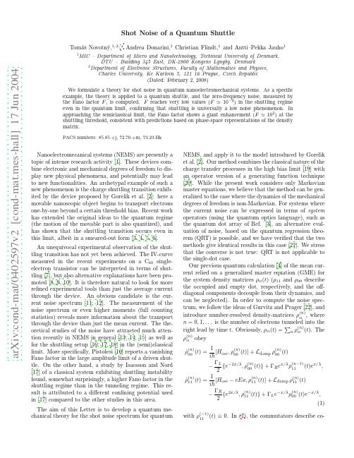
a r X i v :c o n d -m a t /0402597v 2 [c o n d -m a t .m e s -h a l l ] 17 J u n 2004Shot Noise of a Quantum ShuttleTom´a ˇs Novotn´y ,1,2,∗Andrea Donarini,1Christian Flindt,1and Antti–Pekka Jauho 11MIC –Department of Micro and Nanotechnology,Technical University of Denmark,DTU –Building 345East,DK-2800Kongens Lyngby,Denmark 2Department of Electronic Structures,Faculty of Mathematics and Physics,Charles University,Ke Karlovu 5,12116Prague,Czech Republic(Dated:February 2,2008)We formulate a theory for shot noise in quantum nanoelectromechanical systems.As a specific example,the theory is applied to a quantum shuttle,and the zero-frequency noise,measured by the Fano factor F ,is computed.F reaches very low values (F ≃10−2)in the shuttling regime even in the quantum limit,confirming that shuttling is universally a low noise phenomenon.In approaching the semiclassical limit,the Fano factor shows a giant enhancement (F ≃102)at the shuttling threshold,consistent with predictions based on phase-space representations of the density matrix.PACS numbers:85.85.+j,72.70.+m,73.23.HkNanoelectromecanical systems (NEMS)are presently a topic of intense research activity [1].These devices com-bine electronic and mechanical degrees of freedom to dis-play new physical phenomena,and potentially may lead to new functionalities.An archetypal example of such a new phenomenon is the charge shuttling transition exhib-ited by the device proposed by Gorelik et al.[2]:here a movable nanoscopic object begins to transport electrons one-by-one beyond a certain threshold bias.Recent work has extended the original ideas to the quantum regime (the motion of the movable part is also quantized),and has shown that the shuttling transition occurs even in this limit,albeit in a smeared-out form [3,4,5,6].An unequivocal experimental observation of the shut-tling transition has not yet been achieved.The IV-curve measured in the recent experiments on a C 60single-electron transistor can be interpreted in terms of shut-tling [7],but also alternative explanations have been pro-moted [8,9,10].It is therefore natural to look for more refined experimental tools than just the average current through the device.An obvious candidate is the cur-rent noise spectrum [11,12].The measurement of the noise spectrum or even higher moments (full counting statistics)reveals more information about the transport through the device than just the mean current.The the-oretical studies of the noise have attracted much atten-tion recently in NEMS in general [13,14,15]as well as for the shuttling setup [16,17,18]in the (semi)classical limit.More specifically,Pistolesi [16]reports a vanishing Fano factor in the large amplitude limit of a driven shut-tle.On the other hand,a study by Isacsson and Nord [17]of a classical system exhibiting shuttling instability found,somewhat surprisingly,a higher Fano factor in the shuttling regime than in the tunneling regime.This re-sult is attributed to a different confining potential used in [17]compared to the other studies in this area.The aim of this Letter is to develop a quantum me-chanical theory for the shot noise spectrum for quantumNEMS,and apply it to the model introduced by Gorelik et al.[2].Our method combines the classical nature of the charge transfer processes in the high bias limit [19]with an operator version of a generating function technique [20].While the present work considers only Markovian master equations,we believe that the method can be gen-eralized to the case where the dynamics of the mechanical degrees of freedom is non-Markovian.For systems where the current noise can be expressed in terms of system operators (using the quantum optics language),such as the quantum dot array of Ref.[3],an alternative eval-uation of noise,based on the quantum regression theo-rem (QRT)is possible,and we have verified that the two methods give identical results in this case [21].We stress that the converse is not true:QRT is not applicable to the single-dot case.Our previous quantum calculation [4]of the mean cur-rent relied on a generalized master equation (GME)for the system density matrices ρii (t )(ρ11and ρ00describe the occupied and empty dot,respectively,and the off-diagonal components decouple from their dynamics,and can be neglected).In order to compute the noise spec-trum,we follow the ideas of Gurvitz and Prager [22],andintroduce number-resolved density-matrices ρ(n )ii ,where n =0,1,...is the number of electrons tunneled into theright lead by time t .Obviously,ρii (t )= n ρ(n )ii (t ).The ρ(n )ii obey ˙ρ(n )00(t )=12{e −2x/λ,ρ(n )00(t )}+ΓR e x/λρ(n −1)11(t )e x/λ,˙ρ(n )11(t )=12{e 2x/λ,ρ(n )11(t )}+ΓL e −x/λρ(n )00(t )e −x/λ,(1)with ρ(−1)11(t )≡0.In (1),the commutators describe co-2herent evolution of discharged or charged harmonic os-cillator of mass m and frequency ωin electric field E ,re-spectively.The terms involving ΓL,R describe the charge transfer processes from/to leads while the mechanical damping with the damping coefficient γis determined by the kernel (at T =0)[4]L damp ρ=−iγ2[x,[x,ρ]].(2)The mean current and the zero-frequency shot noise are given by [19]I =ed dtnn 2P n (t )− nnP n (t ) 2t →∞,(4)where P n (t )=Tr osc [ρ(n )00(t )+ρ(n )11(t )]are the prob-abilities of finding n electrons in the right lead by time t .Using Eq.(1)we find I = n n ˙P n (t )=ΓR Tr osc e 2x/λρ11(t ),i.e.one recovers the station-ary current used previously [4].In a similar fashion,nn 2˙P n (t )=ΓR Tr osc e 2x/λ 2 n nρ(n )11(t )+ρ11(t ) ,whose large-time asymptotics determines the shot noiseaccording to (4).This can be computed using an operator-valued generalization of the generating func-tion concept.We introduce the generating functionsF ii (t ;z )= n ρ(n )ii (t )z n with the properties F ii (t ;1)=ρii (t ),∂∂tF 00(t ;z )=12{e −2x/λ,F 00(t ;z )}+L damp F 00(t ;z )+z ΓR e x/λF 11(t ;z )e x/λ=L 00F 00(t ;z )+z L 01F 11(t ;z ),∂i[H osc −eEx,F 11(t ;z )]+L damp F 11(t ;z )−ΓR2e 2ΓR=Tr osc e2x/λ2∂∂z1 i =0F ii (t ;z )z =1t →∞.(6)A Laplace transform of (5)yields˜F 00(s ;z )˜F11(s ;z ) =s −L 00−z L 01−L 10s −L 11 −1 f init 00(z )f init 11(z ) (7)where f initii (z )= n ρ(n )ii (0)z n depends on the initial con-ditions.Defining the resolvent G (s )=(s −L )−1of the full Liouvillean we arrive at˜F00(s ;1)˜F 11(s ;1) =G (s ) ρinit 00ρinit 11,(8)∂s P +Q1s P −QL−1Q ,inleading order for small s .The object QL −1Q (the pseu-doinverse of L )is regular as the “inverse”is performed on the Liouville subspace spanned by Q where L is regular (no null vectors).Substituting the asymptotic behavior of the resolventinto Eqs.(8)and (9),keeping only the terms divergent at s =0in both equations,and performing the in-verse Laplace transform [25]we find the following large-t3asymptoticsF 00(t ;1)F 11(t ;1) t →∞→P ρinit 00ρinit 11 = ρstat 00ρstat 11∂ITr osc (e 2x/λΣ11).(11)It is of crucial importance that this expression is inde-pendent of the initial conditions [in thealgebraleadingto(11)thelinearlydivergent termsintand the initial condition terms cancel identically].ΣsatisfiesL Σ= ΓR e x/λρstat 11e x/λ−I eρstat11 ,with Tr sys Σ=0.(12)Equations (11),(12)together with the stationary version of the GMEL ρstat 00ρstat11 =0,with Tr sys ρstat =1(13)form the main theoretical result of this Letter and are the starting point for the calculation of the noise properties of the quantum shuttle.In general,these equations have to be solved numer-ically.However,there is an analytic solution to them in the limit of small bare injection rates compared to damping,i.e.ΓL,R ≪γ≪ω.In this limit the os-cillator gets equilibrated between rare tunneling events and,consequently,the state of the oscillator in a given charge state is close to its corresponding canonical state,i.e.ρstat 00=p 00ρosc (0),ρstat 11=p 11ρosc (eE ),ρosc (l )=e −β(H osc −lx )/Tr osc e −β(H osc −lx )where only the probabil-ities p 00,p 11of the respective occupations are to be de-termined from (13).By tracing Eq.(13)with respectto the oscillator we find −˜ΓL p 00+˜ΓR p 11=0(with p 00+p 11=1)where ˜ΓL =ΓL Tr osc (e −2x/λρosc (0)),˜ΓR =ΓR Tr osc (e 2x/λρosc (eE ))are the renormalized tunneling rates.Proceeding similarly in the evaluation of Σ(this intuitive approach can be easily justified with singular perturbation theory,see e.g.Ref.[20]),we set Σstat 00=s 00ρosc (0),Σstat11=s 11ρosc (eE )and tracing Eq.(12)withrespect to the oscillator we arrive at −˜ΓL s 00+˜ΓR s 11=I˜ΓL +˜ΓR ,F =˜Γ2L +˜Γ2R/mω.Other parameters areeE/mω2=0.5x 0,T =0.The asterisk defines the parameters of Wigner distributions in Fig.2.ratio between the rates:˜ΓR ΓLexp2eE/mω)compared to the λ=x 0case.Thus,already for λ=2x 0the shuttle behaves al-most semiclassically,where a relatively sharp transition between the two regimes is expected.Around the transi-tion the tunneling and shuttling regimes may coexist,as shown analytically in [6].We see this phenomenon ex-4FIG.2:Phase space picture of the shuttle around the tran-sition where the shuttling and tunneling regimes coexist.From left to right we show the Wigner distribution func-tions for the discharged(W00),charged(W11),and both(W tot=W00+W11)states of the oscillator in the phase space(horizontal axis–coordinate in units of x0=exp i P y2π X−y2F ii(t;z)|z=1to yield afinite term.∂z。
Andor_Learning_CCD_Signal_to_Noise_Ratio
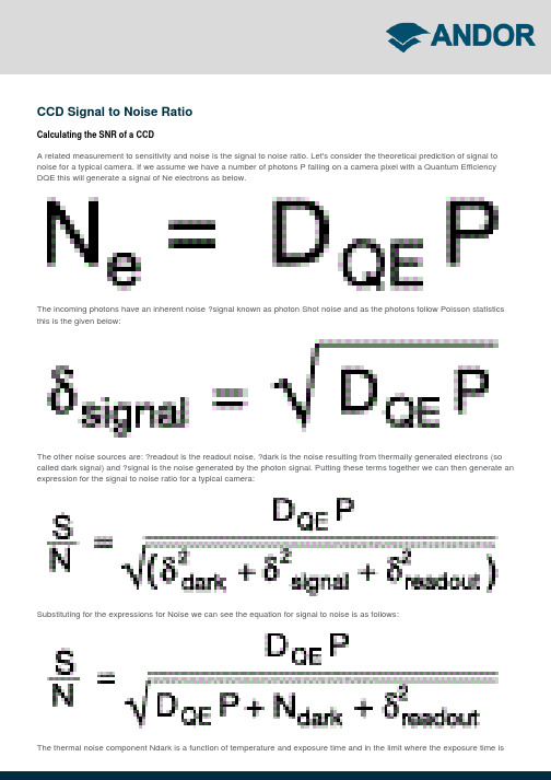
CCD Signal to Noise RatioCalculating the SNR of a CCDA related measurement to sensitivity and noise is the signal to noise ratio. Let's consider the theoretical prediction of signal to noise for a typical camera. If we assume we have a number of photons P falling on a camera pixel with a Quantum Efficiency DQE this will generate a signal of Ne electrons as below.The incoming photons have an inherent noise ?signal known as photon Shot noise and as the photons follow Poisson statistics this is the given below:The other noise sources are: ?readout is the readout noise, ?dark is the noise resulting from thermally generated electrons (so called dark signal) and ?signal is the noise generated by the photon signal. Putting these terms together we can then generate an expression for the signal to noise ratio for a typical camera:Substituting for the expressions for Noise we can see the equation for signal to noise is as follows:The thermal noise component Ndark is a function of temperature and exposure time and in the limit where the exposure time isvery short and the CCD is cooled to a low temperature this term is negligible.We have also neglected other factors that affect the signal to noise especially of EMCCD cameras and ICCD cameras these will be covered in more detail in a later section.The plot for the signal to noise ratio for a typical back illuminated CCD camera versus for an ideal detector is shown in figure 1. In this plot we have taken the example when the readout noise of the CCD is 10e and the QE is 93%.It can be seen by manipulation of the equation that the signal-to-noise ratio approaches that of an ideal detector in the situation when:which can be rearranged as thus:To achieve good signal to noise performance for a camera with a readout noise of 10e- the photons per pixel P must therefore be greater than the read noise squared or ~100electrons.。
Dephasing in a quantum dot due to coupling with a quantum point contact
a r X i v :c o n d -m a t /9702164v 1 [c o n d -m a t .m e s -h a l l ] 18 F eb 1997EUROPHYSICS LETTERSEurophys.Lett.,(),pp.()Dephasing in a quantum dot due to coupling with a quan-tum point contact Yehoshua Levinson Weizmann Institute of Science,76100Rehovot,Israel (received ;accepted in final form )PACS.73.23.-b –Mesoscopic systems.PACS.72.10.-d –Theory of electronic transport;scattering mechanisms.Abstract.–We consider the dephasing of an one-electron state in a quantum dot due to charge fluctuations in a biased quantum point contact coupled to the dot capacitively.The contribution to the dephasing rate due to the bias depends on temperature and bias in the same way as shot-noise in the point contact at zero frequency,but do not follow the |t |2(1−|t |2)suppression.Recently,it became possible to measure the phase and hence also the coherence of resonance electron transmission through a (pinched)quantum dot (QD)[1,2,3,4].Experiments of this type are performed using Aharonov-Bohm rings loaded by a QD in one of its arms,the ring being imbedded in a two-or four-terminal configuration.The conductance of such a system contains a term oscillating with magnetic flux Φthreaded trough the ring and this term is sensitive to the phase of the transmission amplitude t QD through the QD.If the transmission through the QD is coherent one can calculate G from the Landauer formula in terms of the transmission through the ring T .The transmission amplitude t QD through a pinched QD is small (it is true even for resonance transmission,since generically the QD is asymmetric)and for small t QD one finds |T |2=|T |20+Re {a ∗t QD exp(2πi Φ/Φ0)},where Φ0is the flux quanta.The two terms correspond to the non-oscillating and oscillating parts of G in the two-terminal configuration.The first is the transmission trough the ”free”arm and the second is due to the interference between the (multiple)electron paths in the ”free”and ”loaded”arms.The effective ”amplitude”a is responsible for the geometry of thering outside the QD and of the external contacts to the ring.When the temperature T =0all energy depending transmission amplitudes has to be calculated at the Fermi energy ǫF and for T =0one has to average over thermal energies near ǫF .The phase of transmittance trough a QD in an Aharonov-Bohm ring was analyzed in papers [5,6]and also in connection with the ”phase slippage”[7].When the coherence of the electron states in the QD is destructed due to interaction with some ”environment”the amplitude t QD has to be replaced by its average <t QD >with respect to states of the ”environment”.The destruction of coherence is not necessary related to inelastic scattering [8]and this is why we call it ”dephasing”.Typeset using EURO-L A T E X2EUROPHYSICS LETTERS One source of such a dephasing can be the capacitive coupling between the QD and a quantum point contact(PC)which is close in space to the QD[9,10].Chargefluctuations in the PC create afluctuating potential at the QD and modulate the electron states in the QD.This modulation being random in time dephases the states in the QD and destructs the coherence of the transmission through the QD.The chargefluctuations in the PC depend on whether the PC is in equilibrium or supports a current due to an applied bias V.Hence one can expect that the visibility of the ring conductance oscillations withflux will change with current in the PC.The aim of this work is to calculate the dephasing time of a state in a QD induced by its capacitive coupling to a PC.We will be interested mainly in the additional contribution to the dephasing rate which is due to the current in the PC.To simplify the problem we consider dephasing in an isolated QD not coupled to leads and coupled capacitively to a PC.To make things more transparent assume only one state in the QD with energyǫ0and only one channel in the point contact with coordinate x along the channel and an effective one dimensional barrier potential U(x).For simplicity we assume the PC to be symmetric with respect to x=0(the maximum of the barrier).The Hamiltonian of the QD is H QD=ǫ0c+c,where c is an operator removing one electron from the QD state.The Hamiltonian of the PC is(¯h=1)H P C= dxψ+(x) −1dx2+U(x) ψ(x)= kǫk[a+k a k+b+k b k].(1) Hereψ(x)is the electronfield operator,which can be presented as[11]ψ(x)= k[a kχk(x)+b kφk(x)],(2)whereχk(x)andφk(x)are scattering states radiated from the left and right ohmic contacts a and b and belonging to the same energyǫk and a k,b k are the corresponding electron operators. The scattering states have the following properties(k>0)χk(x)=L−1/2{exp(+ikx)+r k exp(−ikx)},for x→−∞,χk(x)=L−1/2t k exp(+ikx),for x→+∞,(3) r k and t k being the reflection and transmission coefficients defined by the potential barrier U(x)and L is some normalization length.Similar equations can be written forφ(x)=χ(−x).The Hamiltonian of the interaction between the QD and PC,assumed to be weak,isH int=c+c W≡c+c dxδU(x)ψ+(x)ψ(x).(4)If one combines H P C+H int one can see thatδU(x)is the average change of the barrier potential U(x)due to one electron occupying the QD state when<c+c>=1.This change is localized near the squeezing of the PC x=0.If one combines H QD+H int one can see that W is the change of the QD state energyǫ0due to the interaction of the electron in the QD with the electron density in the PC.The dephasing of the QD state is described by the relaxation of the average state amplitude <c(t)>,where c(t)=exp(+iHt)c exp(−iHt)is the amplitude in Heisenberg representation with the total Hamiltonian H=H QD+H P C+H int.The Heisenberg amplitude equation of motion is(d/dt)c(t)=i exp(+iHt)[H,c]exp(−iHt)=−i[ǫ0+W(t)]c(t),(5)Y.LEVINSON,DEPHASING IN QUANTUM DOTS3 withW(t)=exp(+iHt)W exp(−iHt).(6) Eq.(5)demonstrates that W(t)is indeed the time depending modulation of the energy level ǫ0.Solving this equation and averaging onefinds<c(t)>= c(0)exp(−iǫ0t)T t exp −i t0dtW(t) ,(7)where T t means time ordering.We decouple the average in Eq.(7)approximating the time ordered exponent by a Gaussian exponent and obtain<c(t)>=<c(0)>exp(−iǫ0t)exp(−Φ(t)),(8)where1Φ(t)=[<W(t)W(0)>+<W(0)W(t)>].(10)2We also approximate W(t)defined in Eq.(6)byW(t)=exp(+iH P C t)W exp(−iH P C t)(11)neglecting the influence of the QD on thefluctuations in the PC.With this approximation the average in Eq.(10)reduces to the average with respect to the state of the PC(in equilibrium or with current)which plays now the role of an environment.This last approximation means that we have in mind an experimental situation when the current in the QD used to measure its linear conductance G is small while the current in the PC can be relatively large.The correlator K(t)decays in time with some time scaleτc which is the correlation time of the QD state energy modulation.For large t≫τc onefind from Eq.(8)<c(t)>=<c(0)>exp(−iǫ0t)exp(−t/τϕ)(12)with12 +∞−∞dtK(t).(13) Hence the average amplitude of the QD state decays.Note that under same conditions the population of the QD state is constant<c+(t)c(t)>=<c+(0)c(0)>,since H int commutes with the number of electrons in the QD c+c.Same is true for the energy of the QDǫ0c+c. This means that the decay of<c(t)>with the time constantτϕis indeed dephasing and not energy relaxation or escape from the QD.Using Eq.(4)and Eq.(2)onefinds the energy modulation in terms of scattering states W= k,k′[a+k a k′A k,k′+b+k b k′B k,k′+a+k b k′C k,k′+b+k a k′¯C k,k′](14)4EUROPHYSICS LETTERS with integrals describing the interaction between the QD and the PCA k,k′= dxδU(x)χk(x)∗χk′(x),B k,k′= dxδU(x)φk(x)∗φk′(x),C k,k′= dxδU(x)χk(x)∗φk′(x),¯C k,k′= dxδU(x)φk(x)∗χk′(x)=C∗k′,k.(15) Using Eq.(14)one canfind(similar to the calculation[12]of the current correlator in a PC)<W(t)W>= k,k′exp[i(ǫk−ǫk′)t]×{n a k(1−n a k′)|A k,k′|2+n b k(1−n b k′)|B k,k′|2+n a k(1−n b k′)|C k,k′|2+n b k(1−n a k′)|¯C k,k′|2},(16) n a k and n b k being the occupation numbers for states with energyǫk in the left and in the right ohmic contacts of the PC a and b respectively,n a,bk=[exp[−(ǫk−µa,b)/T]+1]−1,(17) whereµa,b are the electrochemical potentials in the ohmic contacts a,b and V=−(µa−µb)/e is the applied voltage between a and b(assuming e>0).The spectral density of the QD level modulation can be calculated using Eq.(10)and Eq.(16) as followsS(ω)=12 k,k′δ(ǫk−ǫk′+ω)×{n a k(1−n a k′)|A k,k′|2+n b k(1−n b k′)|B k,k′|2+n a k(1−n b k′)|C k,k′|2+n b k(1−n a k′)|¯C k,k′|2}+{ω→−ω}.(18) To simplify the spectral density assume that the squeezing in the PC(i.e.the barrier U(x)) is described by only one length scale d,the energy spacing between the thresholds for differentchannels in the PC being∆ǫ≃1/md2≪ǫF.With this assumption the scale in k for thecoefficients A,B,C and¯C is d−1.Assume also that the bias in the PC and the temperature are small in the sense that eV,T≪∆ǫ.One can see that with these assumptions the relevantfrequenciesωare much smaller than the inverse of the time offlight through the PC and thatthe main contribution come from states close to the Fermi level.Since|ǫk−ǫk′|≃v F|k−k′|≃ω(where v F is the Fermi velocity)onefinds that forω≪v F/d≪ǫF the relevant|k−k′|≪d−1and one can replace in the coefficients A,B,C and¯C the momenta k and k′by k F.After this replacement we just skip the momenta in the notation and note that|C|2=|¯C|2.Changing summation over k>0to integration overǫk and introducing a function[13] F(ω)= dǫdǫ′[δ(ǫ−ǫ′+ω)+δ(ǫ−ǫ′−ω)]nǫ(1−nǫ′)=F(−ω)(19) onefinds the explicit expression for the spectral densityS(ω)=L2Y.LEVINSON,DEPHASING IN QUANTUM DOTS5 According to Eq.(21)the spectra of the QD energy modulation due to nonequilibrium charge fluctuations in the PC is the same as the shot-noise spectra in the PC[12,13].The typical modulation frequencies are determined by the energy window nearǫF where the electronfluxes from the left and right ohmic contacts a and b of the PC do not compensate,i.e.ω≃eV/¯h for high bias eV≫T andω≃T/¯h for low bias eV≪T.One can check that for low enough temperature and bias T,eV≪∆ǫthese frequencies are indeed smaller than the inverse time of flight.These frequencies also define the correlation time of the QD level modulationτc≃ω−1.However the amplitude of the energy modulation determined by the coupling constantλdepends on the transmittance through the PC in a way very different from that of the shot noise,which is proportional to|t|2(1−|t|2).To see it we can rewrite the coupling constant in terms of changes in r and t introduced by the perturbationδU(x)to the potential U(x).Using the representation of the Green function for the Schr¨o dinger equation with potential U(x)in terms of scattering statesG(x,x′)=(mL/ikt)χ(x>)φ(x<),(22) where x>and x<are the larger and the smaller of x and x′,and also the properties of the scattering states(for a symmetric barrier)χ∗(x)=r∗χ(x)+t∗φ(x),(23) one canfindλ=(8π2)−1|r∗δt+t∗δr a|2=(8π2)−1|r∗δt+t∗δr b|2,(24) whereδr a andδr b are the changes of r for waves coming from ohmic contacts a and b and t is the change in t.Let see how the coupling constant depends on the barrier in the PC.If the barrier U(x) is infinite(|t|2=0)the functionsχandφdo not overlap and it follows from Eq.(15)that |C|2=0andλ=0.Same can be obtained from Eq.(24)since zero transmittance of an infinite barrier can not be changed by afinal perturbation and hence from t=0it follows thatδt=0. It means that what matters for the nonequilibrium dephasing in the QD is not the applied bias in the PC,but the current.In case of an infinite barrier applied bias does not change the electron density and itsfluctuations in the ohmic contacts a and b.If there is no barrier(|t|2=1),i.e.the quantum point contact is replaced by a quantum wire,χandφare plane waves and onefinds from Eq.(24)and Eq.(15)λ=18π2|δr b|2=16EUROPHYSICS LETTERSA similar calculation of the equilibrium part of modulation spectra results inS0(ω)=2(µ+λ)F(ω),(27) where2µ=(L2/8π2v2F)[|A|2+|B|2]=(8π2)−1[|r∗δr a+t∗δt|2+|r∗δr b+t∗δt|2].(28) A cutoffat the time-of-flight frequency v F/d has to be introduced to this spectra,but the equilibrium contribution to the dephasing rate defined by S0(0)is independent on this cutoffand equal toτ−1ϕ=2π(µ+λ)T.(Note that when the thermal current noise at zero frequencyis calculated in this way it is in agreement with the d.c.conductance according to the Nyquist theorem).If the QD is not pinched and the electron in stateǫ0has afinite escape rate to the leadsΓthe dephasing rate competes with this rate.For zero dephasing the(nonaveraged)transmission amplitude t QD contains a resonant factor−i/[(ǫF−ǫ0)+iΓ].Due to dephasing this factor is replaced in the averaged amplitude<t QD>by∞dt exp[−Γt−Φ(t)+i(ǫF−ǫ0)t].(29)Generally the factor Eq.(29)defines a non Lorentzian line-shape but in the case of dynamical narrowing<(δǫ0)2>1/2τc≪1it reduces to−i/[(ǫF−ǫ0)+i(Γ+¯h/τϕ)]just adding the dephasing rate to the escape broadening.Recently the problem of dephasing was also addressed in an unpublished paper of Aleiner, Wingreen and Meir[14]using a different approach.***This work was initiated as a result of discussions with M.Heiblum and E.Buks about the possibility of the so called”Which Path?”experiment in the Aharonov-Bohm interferometer.I acknowledge these discussions very much.I am thankful to Y.Imry for discussions related to level broadening and dephasing rate and also to A.Stern and F.von Oppen for discussing the results of this work.REFERENCES[1]Yacoby A.,Heiblum M.,Mahalu D.,and Shtrikman H.,Phys.Rev.Lett,74(1995)4047.[2]Yacoby A.,Shuster R.,and Heiblum M.,Phys.Rev.B,53(1996)9583.[3]Buks E.,Shuster R.,Heiblum M.,Mahalu D.,Umansky V.,and Shtrikman H.,Phys.Rev.Lett,77(1996)4664.[4]Shuster R.,Buks E.,Heiblum M.,Mahalu D.,Umansky V.,and Shtrikman Hadas,Nature,385(1997)417.[5]Levy Yeyati A.,and Buttiker M.,Phys.Rev.B,52(1995)R14360.[6]Hackenbroich G.,and Weidenmuller H.A.,Phys.Rev.Lett.,76(199)110.[7]Oreg Y.,and Gefen Y.,cond-mat/9607145,(1996).[8]Stern A.,Aharonov Y.,and Imry Y.,Phys.Rev.A,41(1990)3436.[9]Field M.,Smith C.G.,Peper M.,Ritchie D.A.,Frost J.E.F.,Jones G.A.C.,andHasko D.G.,Phys.Rev.Lett,70(1993)1311.[10]Heiblum M.,et al,unpublished,.[11]Buttiker M.,Phys.Rev.B,46(1992)12485[12]Lesovik G.B.,JETP Lett.,49(1989)592.[13]Eric Yang S.R.,Solid State Comm.,81(1992)375.[14]Aleiner I.L.,Wingreen N.S.,and Meir Y.,cond-mat/9702001,(1997).。
专业英语-optical
DWDM Dense wavelength division multiplexing CWDM Coarse Wavelength Division Multiplexing Protocol standard for optical transmission in long-haul communication Sonet (synchronous optical network) OTDR Optical Time Domain Reflectometer
At present, the bandwidth available to fiber systems is not fully utilized but modulation at several gigahertz over a hundred kilometers and hundreds of megahertz over three hundred kilometer without intervening electronics (repeaters) is possible.
The baseline on a spectrum analyzer display Noise floor Diode detector Envelope detector image frequency
纤芯
包层
保护套
jacket
core
coating
A number less than one that indicates the range of angles of light that can be introduced to a fiber for transmission
散粒噪声用于研究超导体性质的实例综述

散粒噪声用于研究超导体性质的实例综述1北京大学物理学院本科毕业论文作者崔治权指导老师危健散粒噪声用于研究超导体性质的实例综述【摘要】 : 散粒噪声是一类重要的噪声信号 , 主要由载流子的离散性造成 ,在载流子通过隧道结时表现得最为明显, 人们可以通过对它的分析获得关于介观系统某些性质的信息, 这些信息往往又是从电导等物理量的平均值测量中不易获得的。
本文将主要介绍近年来在常规以及高温超导体中 , 利用散粒噪声信号研究其性质的典型实例 , 以期对于散粒噪声的特性及其用于研究凝聚态特别是超导体性质的思路和手段进行全面准确的把握 , 从而为实验室下一步研究高温超导体 YBCO 隧道结中散粒噪声信号提供一定的帮助。
【关键词】 :散粒噪声,常规超导体, 高温超导体, 隧道结 ,电输运性质 2北京大学物理学院本科毕业论文作者崔治权指导老师危健目录一、引言 (4)二、散粒噪声的性质及表征..…………………………………………… 51.噪声信号的一般数学描述..................................................................... 52. 热噪声简介 (7)3. 闪烁噪声简介 (7)4. 散粒噪声的产生机制及数学描述 (8)4.1 单电子隧穿一维势垒.................................................................................9 4.2 单电子随机入射一维势垒 (9)4.3 多电子随机入射 (9)三、应用散粒噪声信号研究半导体性质的几个范例........................ 101. 分数量子霍尔效应 (10)2.SNT (shot noise thermometer )标准低温温度计.................................... 133. 量子混沌微腔中的电子散射...............................................................144.小结 (16)四、利用隧道结中散粒噪声研究常规超导体特性的实例............... 171. 超导简介 (17)2. 超导隧道结中电流散粒噪声应用的两个实例....................................17 2.1 无序金属- 超导体隧道结中散粒噪声的特性 (18)2.2 SNS 隧道结中 MARMultiple Andreev Reflection 效应引起的散粒噪声激增 (21)3. 常规超导体中其他未及说明的实例................................................234.小结 (23)五、利用隧道结中散粒噪声研究高温超导体特性的实例……… 241. 高温超导简介…………………………………………………………………… 242. 高温超导隧道结中的散粒噪声………………………………………………… 25 2.1 d- 波超导体 SN 结中散粒噪声与 s- 波超导体中散粒噪声的区别………………………… 25 2.2 YBCO 双晶结中散粒噪声的研究..................................................................283.小结 (29)六、总结与讨论………………………………………………………… 29 3北京大学物理学院本科毕业论文作者崔治权指导老师危健七、参考文献 (30)八、致谢 (31)九、原创性和使用授权说明……………………………………………… 32 4北京大学物理学院本科毕业论文作者崔治权指导老师危健【正文】 :一、引言半导体器件中的噪声信号, 实际上就是指半导体中所通电流或两端测得的电压不会一直保持一个不变的值, 而是会随时间围绕着平均值发生一定的上下波动,这种波动有时甚至会比较剧烈。
第二章电磁干扰源---电磁噪声
散粒噪声电流的有效值定义为: 其中:
q--电子电荷(1.6×10⁻¹⁹C) IDC --流过器件的直流电流的平均值(A) B--噪声带宽(Hz)
它的功率密度与频率无关,其 幅度呈高斯正态分布。
(3)接触噪声(Contact Noise)
当两种材料接触时,接触不 良造成的电导率的波动将会造 成这种接触噪声,很显然,它 存在于两块导体相接触的任何 场合。
自然界中一些材料容易吸附 电子,而另一些则易于失去电子。 下表按照材料电子亲和力的次序 列出了一些典型材料的摩擦序列 表。表中处于顶部的材料易于失 去电子,因而摩擦后生成正电, 底部材料则易于获得电子而带负 电。
两种材料在表中所处的位置相 差越远,并不代表摩擦后生成的 静电荷越多,因为摩擦后生成的 静电荷的多少,不仅取决与它们 在表中的位置,而且还与材料表 面的光洁度、接触的压力和摩擦 后两者分离的速度密切有关。
在工业部门常用的人体静电放电 模型中,等效存贮能量视具体情况 在几毫焦至几十毫焦之间。 显然,如果人体接触一块电路板 或电子装置的某一部分时,就可能 造成静电放电。Ub<3500V时,静电 放电电流可能不一定为人们感觉到, 但一些现代场控器件,甚至因几百 伏的静电放电就可能被损坏。
常见半导体器件的静电放电 易损电压参考值
(3)辉光放电(Glow Discharge)
持续的辉光放电物理现象已 广泛地应用于离子管、等离子 反应器和低压气体放电灯中。 除此以外,在人们所处的电磁 环境中,还存在一些不控的辉 光放电干扰源。
第2章 电磁干扰源---电磁噪声
电磁干扰主要涉及到三个环节: 第一是电磁噪声源; 第二是噪声的耦合途径; 第三是电磁噪声的接收。
本章主要介绍电磁干扰的第一 个环节:电磁噪声。 将按以下三个部分讲解。
全球高精度音频微波电子产品说明书
71MXL LARGE DIAPHRAGM CONDENSER STUDIO MICS Studio condenser microphones with both FET and tube circuitry available. FET models require 48V phantom power, while tube models include power supply.ITEM DESCRIPTIO N PRICE MXL-770...............Cardioid, 6-micron 20mm gold-sputtered diaphragm FET w/shockmount and case,30Hz-20kHz, -10dB pad and bass roll off .................................................................................................89.95 MXL-2003.............Cardioid transformerless condenser w/bass cut and -10dB pad switches, 20Hz-20kHz ........................169.95 PRO-PAC-PLUS+..MXL2003 & MXL603S (transformerless cardioid instrument mic),w/shockmounts, cables, windscreens in padded case ............................................................................279.95 MXL-2006.............Cardioid, true Class 'A' FET preamp w/balanced transformerlessoutput, high-isolation shockmount and case, 30Hz-20kHz .......................................................................99.95 MXL-2010.............3-pattern (cardioid/Figure-8/omni) capsule, FET preamp w/bassroll-off switch, shockmount & windscreen, 30Hz-20kHz .........................................................................169.95 MXL-CUBE............Drum condenser cardioid mic, FET balanced output w/mic clip, 20Hz-20khz ...........................................99.95 MXL-GOLD-35.......Gold-plated cardioid condenser w/shockmount, leather case, windscreen, 20Hz-20kHz ........................695.00 MXL-M3................Cardioid condenser, transformer balanced output, FET preamp, 20Hz-23kHz ........................................249.00 MXL-R77 ..............Classic body Figure-8-patterned ribbon condenser w/wood case,desktop stand, & 25ft XLR cable, 20Hz-18kHz .......................................................................................399.99 MXL-R77-L...........Same as above, but w/custom Swedish Lundahl transformer ................................................................549.95 MXL-R144 ............Figure-8 patterned ribbon condenser, purple & chrome finishw/shockmount, case, cleaning cloth, 20Hz-17kHz ....................................................................................99.99 MXL-TROPHY........Cardioid condenser w/side-tapped capsule & removable nameplate, 20Hz-20kHz ................................199.95 MXL-V6.................Cardioid mic w/balanced FET output stage, case, & clip, 20Hz-20kHz ...................................................299.00 MXL-V67G ............Transformer-balanced cardioid mic w/solid-state preamp & gold grill, 30Hz-20kHz .............................119.95 MXL-V67I .............Same as above but w/2 selectable 1" cardioid capsules (one bright, one warm) & -10dB pad switch ..169.95 MXL-V67Q ............X/Y stereo pattern condenser mic, w/gold-plated grill, 2 externally biased 22mm pressuregradient capsules, 10ft custom XLR cable, 20Hz-20kHz ........................................................................199.95 MXL-V69-MOGAMI-EDITNTransformerless tube cardioid condenser w/shockmount, power supply, 15ft 7-pin cable,15ft XLR cable, cleaning cloth, & case, 20Hz-18kHz ..............................................................................299.95 MXL-V69XM..........Same as above, but w/transformer balanced output, 20Hz-18kHz .........................................................399.00 MXL-V87...............Low-noise transformer-balanced cardioid condenser withFET preamp, w/pop filter & shockmount, 20Hz-20kHz ............................................................................299.95 MXL-V88...............Low-noise cardioid condenser w/balanced transformerless output, FET preamp,high-isolation shockmount & flight case, 20Hz-20kHz ...........................................................................199.00 MXL-V177.............Low noise classic body cardioid condenser w/6-micron thick gold-sputtered diaphragm, 20Hz-20kHz .299.95 REVELATION.........Variable pattern tube condenser mic w/EF86 pentode tube ..................................................................1295.00 GENESIS...............Tube condenser cardioid mic w/-10 dB pad, dedicated power supply ....................................................595.00R144V1772010GOLD-35GENESIS REVELATIONCUBEVIP50DC-196DC-96B72ID The RØDE NT5 is a true condenser microphone specifically two stand mounts and two windscreens. Requires 48V phantom power. Frequency dynamic range >128dB. Available in pairs, or as single RØDE NT2A MULTI-PATTERN LARGE DIAPHRAGM CO NDENSER MIC The successor to the very popular NT-2 studio condenser mic, the NT2A now has the internally shock mounted H F1 dual 1" capsule, the same as is used in the K2 microphone, and new electronics with extremely low 7dBA self-noise. It has a 3-position variable polar pattern for omni, cardioid, and figure-8 patterns, three positions of selectable attenuation (0dB, -5dB, or -10dB) and low freq. roll-off (flat, 80Hz or 40Hz). The NT-2A comes with a soft pouch and mounting clip.ITEM DESCRIPTI O N PRICE NT2A ...................Multi-pattern condenser ................399.00ID phone with an incredible 5dBA self noise figure. 48V phantom power, transformerless output, 137dB max. SPL, fixed cardioid pattern.SCHO EPS CO LETTE MODULAR MIC SETSMicrophones consist of a mic cap-sule and amplifier. The CMC 6 microphone amplifier converts extremely high-imped-ance signals from the attached capsule toa very low-impedance signal suitable for transmission via mic cable. It also featuresa symmetrical Class “A” output stage, free of coupling condensers or an output transformer. They are light-weight, have extremely low distortion, and their very low output impedance helps make them insensitive to electrical interference. The CMC 6 works with both 12V and 48V phantom powering. Matte gray options listed below but also available in nickel. All sets include SG20 stand clamps and B5 popscreens.ITEM DESCRIPTI O N PRICE CMC621G-SET ....Includes CMC 6 amplifier & MK21wide cardioid capsule ..................1632.00 CMC622G-SET ....Includes CMC 6 amplifier, & MK22 open cardioid capsule ........1632.00 CMC64G-SET ......Includes CMC 6 amplifier & MK4 cardioid capsule ..........................1542.00 CMC641G-SET ....Includes CMC 6 amplifier &MK41 supercardioid capsule ........1743.00CMC641CG-SET ..Includes CMC 6 amplifier & MK41 super-cardioid capsule, CUT 1 filter ......2320.00CMC65G-SET ......Includes CMC 6 amplifier &MK5 omni/cardioid capsule..........2059.00CMC68G-SET ......Includes CMC 6 amplifier &MK8 figure-8 capsule...................1938.00NEAR-FIELD-OMNI-STIncludes 2 CMC 6s, matched pairof MK2 omnis ...............................3150.00UNIVERSAL-OMNI-H-STIncludes 2 CMC 6s, matched pairof MK2 H omnis ............................3214.00UNIVERSAL-OMNI-S-ST ........................................................Includes 2 CMC 6s, matched pairof MK2 S omnis ............................3150.00WIDE-CARDIOID-STIncludes 2 CMC 6s, matched pairof MK21 wide cardioids ................3199.00OPEN-CARDIOID-STIncludes 2 CMC 6s, matched pairof MK22 open cardioids ...............3199.00CARDIOID-ST ......Includes 2 CMC 6s, matched pairof MK4 cardioids ..........................2999.00SUPERCARDIOID-STIncludes 2 CMC 6s, matched pairof MK41 supercardioids ...............3439.00SWITCHABLE-PATTRN-STIncludes 2 CMC 6s, matched pairof MK5 omni/cardioids ......................CALL MK21MK5MK41MK8MK22MK4NEUMANN KM180 SERIES The KM180series condensers offer the same trans-formerless circuitry as the KM100s without the 10dB pad. Frequency response is 20Hz-20kHz. The KM183, KM184 and KM185 have SPL han-dling of 140dB, 138dB and 142dB respec-tively. 48V phantom power is required.ITEM DESCRIPTI O N PRICE KM183 ................Omni condenser mic ......................899.95KM184 ................Cardioid condenser mic .................849.95KM185-SILVER ...Hypercardioid condenser mic .........899.95EA2124A .............Optional suspension mount ...........279.01WNS100 .............Replacement windscreen .................26.07WS100................Optional 90mm windscreen .............28.03SKM183-MT ........Stereo mic pair-omni,w/case, black ...............................1699.95SKM183-SILVER .Stereo mic pair-omni, w/case ......1699.95SKM184-MT ........Stereo mic pair-cardioid,w/case, black ...............................1599.95SKM184-NI .........Stereo mic pair-cardioid,w/case, nickel ..............................1599.95NEUMANN U87AI 3-PATTERNA legendary FET large diaphragmtransformer coupled studio mic withomni, cardioid and figure-8 patterns,N PRICEMXL SMALL DIAPHRAGM CONDENSER MICS These small diaphragmcondenser mics are quiet, sensitive, rugged enough for the road and inexpen-sive. They are an excellent choice for drum overheads and for close recordingof acoustic instruments. 48V phantom power required.ITEM DESCRIPTI O N PRICE MXL-603PAIR .....Stereo pair of transformerless cardioid instrument mics, 30Hz-20kHz,w/ MXL-41-603 shockmounts & case ................................................................................199.00MXL-604.............Small diaphragm cardioid condenser, 30Hz-20kHz, w/ wooden case,mounting clip and omnidirectional capsule.........................................................................83.93MXL-V67N ..........Small diaphragm instrument condenser, omni/cardioid capsules, 20Hz-20kHz ................119.95MXL-41-603 .......Replacement shockmount for MXL-603PAIR ........................................................................38.95603PAIR ID This mic sure level of 144dB, which is good forrecording amps, drums, and other loudinstruments. Acoustic instruments willbenefit from the TLM102’s fast transientresponse. The TLM102 also features a slight boostNEUMANN TLM103/TLM103D These are large diaphragm cardioid mics with a transformerless output stage. Designed primarily for vocals, the TLM03 also excels on piano, percussion, and stringed instru-ments. The TLM103D is a digital version of the mic, designed for home recording and project studios. Its A/D converter receives the output signal directly from the capsule, ensuring that the signal has no coloration and superb transparency. Both mics require 48V phantom power and come with We service many of the major brands that we carry.Call our Authorized Repair Department at ext. 1172Honesty and Valuesince 197173Thisrugged system has separate capsules and powering modulesthat can be combined to produce a wide variety of microphones.A single module and a few capsules can provide the user withflexibility that would otherwise require investing in a numberof individual microphones. It converts quickly from one type ofmicrophone to another by simply threading together varioussystem components. All capsules use back-electret technologyfor uncompromised quality. Output of all powering modules isbalanced, low impedance (200ohms) and terminates in a stan-“Universal” powering module for the sys-tem. Powered by a single 1.5V “AA” battery with a life of 150 hours, or phantom power SHURE KSM42 & KSM44A LARGE Premium side-address mics offering a dual-diaphragm design with an active front, ultra thin (2.5 micron) 24-karat gold, low mass, 1" Mylar® diaphragm. The KSM42 is ideal for vocal applications with a tailored frequency nal pop filtering. The single-pattern design exhibits smooth proximity control & ultra-wide dynamic range. An internal shock KSM42KSM44A SSED SINGLE-DIAPHRAGM For studio recording and live sound production. The KSM32 offers an extended frequency response of 20Hz-20kHz for an open, natural sound. The Class “A” transformerless preamp circuitry eliminates cross-over distortion for improved linearity across the full frequency range. mass diaphragm provides extended low frequency response and excellent transient microphones feature 20Hz-20kHz frequency response, a 3-position pad switch, a 3-position LF filter, and include a windscreen and carrying case. The KSM137 is a single pattern cardioid mic, while the KSM141 is a dual ...............................665.00 ...............................870.00 PRICE NDENSER The e614 has a super-cardioid pattern, with a neutral response and moderate sensitivity, which insures optimum isolation from other instruments on stage. Unobtrusive for precise place-ment and powered by external phantom power (P48), the e614 tolerates extremely high SPLs, precisely capturing cymbals and hi-hats better than other mics in its price range. 10-year warranty. Frequency response is 40Hz-20KHz.PRICE A large diaphragm side-address microphone with a car-dioid pickup pattern and a nickel colored finish. It has a large 1" diaphragm precisely sputtered with 24-carat gold. It has a sturdy metal housing and the elastically mounted capsule suppresses handling noise. It has a max SPL level of 140dB and a low self-noise level of 10dB(A). It has a frequency response of 20Hz-20kHz, a sensitivity rating of 25mV/Pa and a dynamic range ING SOON!99.9574at home in sound reinforcement systems or in sound studios and motion picture/ TV scoring stages. When used with the optional windscreen, the SM94 can be used by vocalists and speechmakers who desire a wide, flat z and a uniform SHURE PG27LC & PG42LC SIDE ADDRESSThese mics feature acardioid pickup pattern, large diaphragm capsules withswitchable attenuators. The PG27LC is designed for usewith instruments. It has a flat, neutral frequency responsefeatures a voice-tailored frequency response of 20Hz-20kHz as well as an SPL rating PG42LC PG27LC NDENSER ect choice for y demo tapes, les om pow-STC2OMEGA ORPHEUS STC1HELIOS STC10STC2X STC20SATURN studio environments. Features interchangeable capsules for superior versatility. The small diaphragm design provides superior audio with con-sistent, textbook polar responses and is small enough to use in the tightest conditions. The compact side-address design features an innovative lock-ing ring to provide secure connection between capsule and preamplifier. The 20Hz-20kHz frequency response is tailored for wide dynamic range applications for use in high SPL environments. Ships with stand adapter, LET DESIGN BLACK KNIGHT ID PRICE VISIT OR CALL 800-356-5844 FOR MORE INFO We have the largest selection of hard to find items. Call us!Honesty and Valuesince 197176VIOLET DESIGN PEARL SERIES CARDIOID CONDENSER These mics have a rear-ported spherical head and nar-row tapered form reflector to reduce internal resonances and optimize the cardioid polar pattern. The Pearl Standard uses a medium single-diaphragm to provide a modern,airy and detailed sound while the Grand Pearl uses a largedual-diaphragm, providing the warm, classic sound usuallyassociated with vintage studio microphones. Pearl Vocal is ahandheld stage vocal mic, and has special shockmounting forreduced handling noise, a special mid-sized capsule designedfor high gain before feedback with extended flat LF responseand outstanding dynamic range. All models include wood box and stand clip.NES These are side-addressed, cardioid, large dual diaphragm vacuum-tube studio microphones in 3 variations, with acous-tically-transparent head construction and internal shock-mounts. The 6267 vacuum tube preamplifier is a Class “A” fully-discrete circuit with massive heatsink, very high output, flat audio-response and ultra-low noise and distortion. The large custom-wound Permalloy humbucking audio trans-former adds even more “analog warmth” to the sound with wide frequency response and minimum saturation. ComesVIOLET DESIGN AMETHYST CONDENSER STUDIO MICSThe Amethyst cardioid studio microphones use fully-discrete,phantom-powered Class “A” transformerless amplifiers. TheAmethyst Standard uses a single diaphragm center-terminatedcapsule which provides modern, detailed sound with airy highs,medium vocal presence and accentuated low-end response.The Amethyst Vintage uses a dual-diaphragm, dual-backplatecapsule which provides a classic, wide-spectrum, vintage micro-phone sound. Both models have a uni-directional cardioid polarpattern with minimal proximity effect and are linear over the wide frontal incidence NDENSER MICS The Flamingo Junior series are side-addressed studio microphones that use a single-diaphragm, cardioid electrostatic transducer which provides vintage tone with transparent highs, optimized vocal presence and fundamental low-frequency register with minimal proximity effect. An integrated capsule shockmount within the head and an included external compact studio shock-mount reduce stand rumble and mechanical shocks. The custom-wound large humbucking audio transformer adds “analog warmth” to the sound. Comes - Globe features transformerless Class “A” discreet electronics, internal shockmounts for both electronics and capsule, and a spherical and acoustically transparent head design. The Globe Standard has a classic wide-spectrum sound ideal for orchestral applications. The Globe Vintage uses a different dual-diaphragm capsule providing a sweet and warm, vin-tage vocal microphone sound. Comes in a wooden box with shockmount.GLOBE-STANDARD An electrostatic multi-pattern studio mic with a vintage sound, warmed by vacuum tube circuitry and an output transformer. Features specially designed large dual-diaphragm transducer, and 9 different polar patterns. Its Class “A” fully-discrete internal vacuum tube preamp provides high output, low impedance and low distortion. A large humbucker, custom-wound audio transformer balances the microphone’s output, providing additional analog warmth to the sound. Soft starting, smart power supply and external elastic This large dual-diaphragm cardioid con-denser studio microphone has a warmer smooth tone with very high output and low noise. The fast transient response, crystal clear highs and loud SPL handling make it excellent for recording drums. The multi-layered wedge shaped brass mesh head design effectively reduces plosive sounds and breath, pop or wind noises. The internal solid state preamplifier is a Class“A” fully discrete transformerless circuit, and runs on 48V phantom power.PRICE 679.0099.00ID rating an integrated, tapered reflector which reduces resonances, removes reflections and tern. Integrated damping of the transducer reduces stand rumble, outside infrasonic FRR A compact electrostatic mic preamp body for use with vintage German-made M-series inter-changeable capsule heads, as well as B-series and VIN-seriesinterchangeable capsule heads made by JZ in Latvia. The elec-tronics are phantom powered, with a linear Class “A” discretesolid state transformerless design to provide extremely low self-noise and distortion. The Global Pre provides a low-impedance,balanced output on a gold-plated 3-pin XLR. It comes in a woodenVIN47GLOBAL-PREM COMPATIBLE。
CCD的散弹噪声
Shot noise is a type of electronic noise that occurs when the finite number of particles that carry energy, such as electrons in an electronic circuit or photons in an optical device, is small enough to give rise to detectable statistical fluctuations in a measurement. It is important in electronics, telecommunications, and fundamental physics.It also refers to an analogous noise in particle simulations, where due to the small number of particles, the simulation exhibits detectable statistical fluctuations not observed in the real-world system.The magnitude of this noise increases with the average magnitude of the current or intensity of the light. However, since the magnitude of the average signal increases more rapidly than that of the shot noise (its relative strength decreases with increasing signal), shot noise is often only a problem with small currents or light intensities.The intensity of a source will yield the average number of photons collected, but knowing the average number of photons which will be collected will not give the actual number collected. The actual number collected will be more than, equal to, or less than the average, and their distribution about that average will be a Poisson distribution.Since the Poisson distribution approaches a normal distribution for large numbers, the photon noise in a signal will approach a normal distribution for large numbers of photons collected. The standard deviation of the photon noise is equal to the square root of the average number of photons. The signal-to-noise ratio is thenwhere N is the average number of photons collected. When N is very large, the signal-to-noise ratio is very large as well. It can be seen that photon noise becomes more important when the number of photons collected is small.[edit] Intuitive explanationShot noise exists because phenomena such as light and electrical current consist of the movement of discrete, quantized 'packets'. Imagine light coming out of a laser pointer and hitting a wall. That light comes in smallpackets, or photons. When the spot is bright enough to see, there are many billions of light photons that hit the wall per second. Now, imagine turning down the laser brightness until the laser is almost off. Then, only a few photons hit the wall every second. But the fundamental physical processes that govern light emission say that these photons are emitted from the laser at random times. So if the average number of photons that hit the wall each second is 5, some seconds when you measure you will find 2 photons, and some 10 photons. These fluctuations are shot noise.An analogy is to think of what happens when you pour sugar out of a cup. Start off by tilting the cup a lot so that a lot of sugar runs out. Now, decrease the tilt so less and less sugar pours out each second, until only 5 sugar grains are dropping out each second. Even if you hold the cup perfectly still, you won't get exactly5 grains to come out every second -- sometimes you will see 2 grains and sometimes you will see 10. The physics that governs how sugar grains fall off a pile causes the number to be random, just like the physics that governs light emission from a light source. And for large flows, shot noise is not important -- when you tip the cup a lot, the small fluctuations due to random individual grains become small relative to the large continuous flow.[edit] In electronic devicesShot noise in electronic devices consists of random fluctuations of the electric current in many electrical conductors, which are caused by the fact that the current is carried by discrete charges (electrons). This is often an issue in p-n junctions. In metal wires this is not an issue, as correlations between individual electrons remove these random fluctuations. [1][2]Shot noise is to be distinguished from current fluctuations in equilibrium, which happen without any applied voltage and without any average current flowing. These equilibrium current fluctuations are known asJohnson-Nyquist noise.Shot noise is a Poisson process and the charge carriers which make up the current will follow a Poisson distribution. The current fluctuations have a standard deviation ofif the noise current is filtered with a filter having a bandwidth of 1 Hz.If this noise current is fed through a resistor the resulting noise power will beIf the charge is not fully localized in time but has a temporal distribution of q F(t) where the integral of F(t) over t is unity then the power spectral density of the noise current signal will be,A similar lower bound of quantum noise occurs in linear quantum amplifiers. The only exception being if a squeezed coherent state can be formed through correlated photon generation. The reduction of uncertainty of the number of photons per mode (and therefore the photocurrent) may take place just due to the saturation of gain; this is intermediate case between a laser with locked phase and amplitude-stabilized laser.Low noise active electronic devices are designed such that shot noise is suppressed by the electrostatic repulsion of the charge carriers. Space charge limiting is not possible in photon devices.A photon noise simulation, using a sample image as a source and a per-pixel Poisson process to model an otherwise perfect camera (quantum efficiency = 1, no read-noise, no thermal noise, etc).Going from left to right, the mean number of photons per pixel over the whole image is (top row) 0.001, 0.01, 0.1 (middle row) 1.0, 10.0, 100.0 (bottom row) 1000.0, 10000.0 and 100000.0. Note the rapid increase in quality past 10 photons/pixel. (The source image was collected with a camera with a per-pixel well capacity of about 40,000 electrons.)Please click on the image to see the larger form; the low-level images are mainly isolated pixels, and your browser (or wikipedia's server) may be downsampling them to black.Photon noise is the dominant source of noise in the images that are collected by most digital cameras on the market today. Better cameras can go to lower levels of light -- specialized, expensive, cameras can detect individual photons -- but ultimately photon shot noise determines the quality of the image.。
Multisim电路设计与仿真14第10章习题答案
第10章习题参考答案
1.答、热噪声(Thermal Noise):也就是约翰逊噪声(Johnson Noise)或白色噪声(White Noise),这种噪声敏感于温度的变化,由导体中的自由电子和振动粒子之间的热量的相互作用而产生,它的频率在频谱总均匀分布。
散粒噪声(Shot Noise):这种噪声是由各种形式半导体中载流子的分散特性而产生的,这种噪声为晶体管的主要噪声。
闪烁噪声(Flicker Noise):又称为超越噪声(Excess Noise)、粉红噪声(Pink Noise)或1/f噪声,通常由双极型晶体管(BJT)和场效应管(FET)产生,且发生在频率小于1kHz 以下。
闪烁噪声是所有线性器件固有的随机噪声,噪声振幅与频率成反比,频率很低时这种噪声较大,频率较高时(几百赫兹以上)这种噪声的影响较小。
在电路的输入端,闪烁噪声通常是频率低于400Hz时的主要噪声源。
2答:失真分析(Distortion Analysis)用于分析电子电路中的非线性失真和相位偏移,通常非线性失真会导致谐波失真,而相位偏移会导致互调失真。
3、建立10-44仿真电路
对该电路进行静态工作点分析的结果如下图10.1所示。
图10.1
对6节点进行交流分析的结果如下图10.2所示。
图10.2
对节点6进行瞬态分析的结果如下图10.3所示,其中End time(TSTOP)设置为0.1s。
图10.3。
ShotNoise
1Shot Noise1.1History and BackgroundShot noise is due to the corpuscular nature of transport.In1918,Walter Schottky discovered Shot noise in tubes and developed Schottky’s theorem.Shot noise is always associated with direct currentflow.In fact,it is required that there be dc currentflow or there is no Shot noise.Electrical currents do notflow uniformly and do not vary smoothly in time like the standard waterflow analogy.Currentflow is not continuous,but results from the motion of charged particles(i.e.electrons and/or holes)which are discrete and independent.At some (supposedly small,presumed microscopic)level,currents vary in unpredictable ways.It is this unpredictable variation that is called noise.If you could“observe”carriers passing a point in a conductor for some time interval you wouldfind that a“few”more or less carriers would pass in one time interval versus the next. It is impossible to predict the motion of individual electrons,but it is possible to calculate the average net velocity of an ensemble of electrons,or the average number of electrons drifting past a particular point per time interval.The variation about the mean value or average of these quantities is the noise.In order to“see”Shot Noise,the carriers must be constrained toflow past in one direction only.The carrier entering the“observation”point must do so as a purely random event and independent of any other carrier crossing this point.If the carriers are not constrained in this manner then the resultant thermal noise will dominate and the Shot Noise will not be“seen”.A physical system where this constraint holds is a pn junction.The passage of each carrier across the depletion region of the junction is a random event,and because of the energy barrier the carrier may travel in only one direction.Since the events are random and independent,Poisson statistics describe this process.To try andfind the statistics of this process will require a physical model to analyze, therefore we will consider an LC tank circuit.1.2Derivation of Shot NoiseAs an illustration think about an LC tank circuit being charged through an ideal switch(such as an ideal pn junction diode)from a battery with a voltage V.Now the switch is capable of turning on and offin such a short time interval that only single electrons pass through to the tank circuit.Therefore the current pulse is negligible.Also the switch randomly turns on and offsuch that the current pulses are independent and uncorrelated.Then we canapproximate the currentflowing into the tank circuit as a spike of current or delta functionI(t)=jqδ(t−t j),(1) where the t j’s are the random arrival times of the electrons.What we know about t j is that on average there should be¯I/q of them per unit of time following the definition of current.Now,what does one of these current pulses do to the LC circuit?A short pulse of current is not going to go through the inductor,so it must end up charging the capacitor. This will produce a rapid change in the voltage on the capacitor whose magnitude isδV=q/C.(2) If initially the LC circuit contained no energy(i.e.voltage and current identically zero), thefirst pulse of current would start the circuit oscillating with a voltage amplitude of δV.Subsequent pulses of current would arrive at unpredictable times within the period of oscillation,so that some pulses might increase the amplitude of the oscillation and others might decrease the amplitude.Let us write the voltage on C asV(t)=V a expi t/√rather than of the LC tank circuit.The underlying concept is that the noise is distributed over a spectrum of frequencies,and the form of the distribution function,or noise spectrum is the key property.A physical switch that has this property is a pn junction diode.It is well known that semiconductor diodes exhibit Shot noise.This is because the built-in potential across the depletion layer of the pn junction is high enough to prevent the majority carriers from returning once they cross the junction.The transit time across the depletion region is the key time constant for the diode and the carrier arrival is an independent and random event.We will examine the mathematical machinery by which one evaluates the noise spectrum, and then apply it tofind Shot and Thermal noise.The mathematical object which allows us to characterize the duration of the current pulse is called the autocorrelation function and is defined byR I(t )=limT→∞1i2/∆f.These definitions follow from the facts that only real,positive frequencies are used in circuit analysis and that for a noise process the mean is always zero so that the variance is equal to the mean-square value.The two-sided spectral density is an even function of frequency so that S(f)=S(−f) which leads to the fact that S(f)=2S(f),for f≥0and provides the factor of2in the Fourier transform(5).Now,we apply(4)to(1)tofind the autocorrelation of delta-function current pulses.R I(t )=limT→∞q2Tkkδ(t k−t k +t ),(6)where the properties of the delta function are used to evaluate the integral.Now,consider the terms in the double summation above.In the case where the summation indices are k=k which means the arrival times are equal t k=t k ,we just haveδ(t ),and if there are N valuesof t k such that−T/2<t k<T/2,these terms will contribute Nδ(t )to the autocorrelation function.For t k=t k ,the delta functions will occur at randomly distributed,nonzero values of t .We argue that,with suitable averaging,the contributions from these delta functions to the Fourier transform in(5)will vanish.(Note,however,that entire textbooks have been written on the details that are hidden in the phrase“suitable averaging.”)So,the part of the autocorrelation function which remains is given byR I(t )=q¯Iδ(t ),(7)where we have used N/T=¯I/q with¯I being the dc current.Taking the Fourier transform(5):(F{δ(t)}↔1);wefind Schottky’s theoremS I(f)=2q¯I.(8) The spectrum is uniform and extends to all frequencies.This kind of spectrum is calledwhite and many textbooks use the symbol S I(0)to mean no frequency dependence.Now,let us consider the case for the current pulses being of significant duration.In particular,supposeI(t)=q s(t−t k),(9)kwhere s(t)is a square current pulse of durationτ,as illustrated in Figure1.The auto-tt−τt’Figure1:A square current pulse of durationτand its autocorrelation function correlation function can be found by a similar argument to that which we made for the delta-function case earlier and leads toR I(t )=q¯I s(t)∗s(t+t ),(10)where s ∗s is the autocorrelation function of s ,and is shown in Figure 1.The Fourier transform of a single triangle is:F 1−|t |/τ:|t |≤τ0:|t |>τ↔τ sin(πfτ)πf ¯τ 2.(11)This equation gives the same result as (8)at low frequencies,but has a cutoffat f =1/¯τasshown in Figure2.fFigure 2:The frequency spectrum of the autocorrelation function for Shot noiseThis figure of the spectrum is exaggerated because ¯τis the mean transit time of the electrons crossing the depletion region of the diode (≈10ps),which means the cutofffre-quency is about 100GHz.Therefore the approximate equation (8)which implies that Shot noise is independent of frequency is good for almost all integrated circuit design.While thefrequency distribution of S I (0)=2q ¯Iis white ,the amplitude distribution is Gaussian due to the Central Limit Theorem (random walks using a very large number of steps).1.3van der Ziel’s Derivation of Shot NoiseTofind thefluctuation,first define N as the number of carriers passing a point in a timeintervalτat a rate n(t).ThenN= τn(t)dt,(12)¯N=¯nτ,(13)where¯N and¯n are ensemble averages and this results follows from the fact that time averages equal ensemble averages(the Ergodic theorem).If we define a new random variable∆N such that∆N=N−¯N,(14)then we have removed the“d.c.”term leaving only thefluctuation.If we also define the random process Xτthen for sufficiently largeτwe haveXτ=∆NN2and¯n=var n,therefore∆N22=¯Nτ2=var nX2τ.(17)Now applying the Wiener-Khintchine theorem yieldsS n(0)=limτ→∞2τ。
- 1、下载文档前请自行甄别文档内容的完整性,平台不提供额外的编辑、内容补充、找答案等附加服务。
- 2、"仅部分预览"的文档,不可在线预览部分如存在完整性等问题,可反馈申请退款(可完整预览的文档不适用该条件!)。
- 3、如文档侵犯您的权益,请联系客服反馈,我们会尽快为您处理(人工客服工作时间:9:00-18:30)。
a r X i v :c o n d -m a t /0502390v 1 [c o n d -m a t .m e s -h a l l ] 16 F eb 2005Shot Noise for Entangled Electrons with Berry PhaseHui Zhao 1,2,Xuean Zhao 1,and You-Quan Li 11Zhejiang Institute of Modern Physics,Zhejiang University,Hangzhou 310027,China2Department of Physics,Anshan Normal University,Anshan 114005,China(Dated:December 29,2004)We study shot noise for entangled electrons in a 4-lead beam-splitter with one incoming lead driven by adiabatically rotating magnetic fields.We propose a setup of an adiabatically rotating magnetic field therefor,which is appropriate for an electron beam to transport ing the scattering matrix approach,we find that shot noise for the singlet and that for the entangled triplet oscillates between bunching and antibunching due to the influence of the Berry phase.It provides us a new approach for testing the Berry phase in electron transport on the basis of entanglement.PACS numbers:72.25.-b,03.65.Vf,03.67.MnSince the quantum interference and quantum entan-glement in electron transport become very important,the study of biparticle system has absorbed much at-tention recently.The extension of the scattering matrix approach [1]to deal with a biparticle system in a beam-splitter [2,3]is instructive [4].Within the extension,en-tangled states are identified via shot noise measurement.Some application of the extended approach involves deal-ing with entangled states affected by an interaction,such as the Rashba interaction [5].Because the interaction af-fects entangled states,it will finally affect the transport current and shot noise which explicitly involve the effects of interaction.This provide us an approach to probe the properties of the interaction.As to the Berry phase [6],it is studied very well theoretically and experimentally [7]in a single-particle system.However,the interest in the Berry phase of a biparticle state has just been aroused since the work of Sj¨o qvist [8].Two aspects of the Berry phase for a biparticle system are very important.One is how the Berry phase changes due to the interparticle interaction [8,9,10],the other is how it affects the bi-particle state [11].All those advancements lead us to a way to observe the Berry phase in electron transport with an entangled state driven by adiabatically rotating magnetic fields.In this Letter,we study the transport properties of en-tangled electrons in a beam-splitter configuration [2,3]with an incoming lead driven by adiabatically rotating magnetic fields.We propose a setup which is appropriate for an electron beam to transport through therefor.The Berry phase affects the spin states of a single electron sig-nificantly.The application of this set up can make entan-gled state into a superposition of the singlet and triplets.We calculate shot noise for one outgoing lead by means of scattering matrix approach [1]We find the Berry phase affects the entangled state and shot noise for the mutated state oscillates as a function of the Berry phase,which helps us to observe the Berry phase in electron transport on the basis of entanglement.The conventional adiabatically rotating magnetic field is considered around a fixed point,but it is not suitable for an electron to transport.We propose a setup which is suitable for an electron beam to transport through.Thesetup consists of a cylinder,two magnets,two magnetic stripes and two metal stripes.The cylinder is displaced between the two magnets,around whose surface the two magnetic stripes and the two metal stripes are wound he-lically,as shown in Fig.1schematically.Our purpose is to make electrons travelling along the axis of the cylinder feel a right-handed rotating magnetic field.Thus we need to realize the two components of the rotating magneticfield as follows.The constant axial component Bz is pro-duced by the two magnets.Each magnet is made with a hole coaxial to the cylinder,so that electrons can en-ter or leave the cylinder through the hole.In our setup,the radial component B⊥distributes uniformly but ro-tates helically along the axis of the cylinder,which is produced in the following way.Starting from two oppo-site positions at one end of the cylinder,we wind twozmagnetic fieldelectric field (b)z : southern pole : northern pole : cathode: anode NS NS FIG.1:Schematic view of a design of an adiabatically rotat-ing magnetic field.(a):the design of an adiabatically rotating magnetic field,which is appropriate for an electron beam to transport through it.It consists of two magnets to produce a constant magnetic field component along the z axis,two magnetic stripes to produce a helically radial magnetic field component and two metal stripes to produce a radial elec-tric field.(b):the configuration of the radial magnetic field component and the radial electric field.2magnetic stripes around its surface respectively with a right-hand uniform helix such that they undergo a twist of 2πwhen arriving at the other end.We keep the in-ward poles of the two magnetic stripes opposite.These two magnetized stripes clearly produce the wanted com-ponent B⊥.However,when an electron moves along the axis of the cylinder,it will suffer a Lorentz force arising from this component.The Lorentz force will make the moving electron deviate away from the axis of the cylin-der.In order to prevent such derivation,an electronic force to balance the Lorentz force is necessary.This is re-alized by two parallel metal stripes wounded alternately with the two magnetic stripes and connected to the cath-ode and the anode of a battery respectively.The radial magnetic field component and the electrical field along the axis of the cylinder are illustrated in Fig.1(b).Thus the magnetic field in the cylinder takes the form B (z )=B n (z )=B sin ϑcos 2πLz +ϕ,cos ϑ ,(1)where B =2B (z )· σ,(2)where σ=(σx ,σy ,σz )denotes the Pauli operator andµ=gµB the coupling constant in which g is the Land´efactor and µB =1m the Bohr magneton.Then the local energy eigenstates of the Hamiltonian (2)is given by|↑n (z ) =cosϑLz +ϕ)sinϑ2|↑ +e i (2π2|↓ .(4)where |↑ and |↓ refers to the two eigenstates of σz op-erator.The eigenenergies of |↑n (z ) and |↓n (z ) are µB/2and −µB/2respectively.If an electron is travelling along the axis of the cylin-der at speed v ,it will feel that the rotating frequency of the magnetic field ω=2πv/L .We can control electrons’speed v ,let ω=2π2 ,so that the adiabatic condi-tion is satisfied.As the magnetic field at z =L returnsto its original direction at z =0,i.e. B(L )= B (0),the evolution of the electron state is cyclic.According to the adiabatic theorem in quantum mechanics [6],the local energy eigenstates (3)and (4)acquire extra phase factors in addition to the dynamical phase factors:|↑n (L ) =e iδe iγB |↑n (0) ,(5)|↓n (L ) =e −iδe −iγB |↓n (0) ,(6)where δ=Lµ2|↑n (0) −sinϑ2|↑n (0) +cosϑ2e −iδe −iγB +cos 2ϑ2cosϑ2cosϑ2e iδe iγB +cos 2ϑration of γB from the total phase requires very precise control of the system in experiment[12].As is known the spin-echo technique [11,13]is appli-cable for cancelling out the dynamical phase shift.We apply a second setup similar to what we described in Fig.1but turning each magnet to the opposite direction and rotating the cylinder by π.This provides a rotating mag-netic field with the opposite direction in comparison to the first one,i.e.,ϑ→π−ϑand ϕ→π+ϕin Eq.(1).Let the electron just passing through the first setup in-ject into the second setup.Clearly,the outgoing states (9)and (10)are the incoming states with respect to the second setup.The outgoing states after passing through the second cylinder are obtained as follows|χ↑ out2=sin 2ϑ2e2iγB|↑ +sin ϑ2e iϕ e 2iγB −e −2iγB |↓ ,(11)|χ↓ out2=sinϑ2e −iϕe 2iγB−e −2iγB |↑ + sin 2ϑ2e−2iγB|↓ ,(12)in which the dynamical phases are cancelled completely.Eqs.(11)and (12)exhibit that the rotating magnetic fields alter the polarization direction of electron spins.It therefore suggests a route for spin control [14]merely bymeans of the justification of the magnitudes of B⊥and Bz .4321SplitterBeam fields' regionE n t a n g l e rFIG.2:The sketch picture of a 4-lead beam-splitter,in which two adiabatically rotating magnetic fields are displaced in lead 1.Now we are in the position to study the transport properties of electrons in an entangled system with one subsystem evolving in adiabatically rotating magnetic fields.We suggest a scheme based on the one presented in Ref.[4,5],but displacing two afore-mentioned adia-batically rotating magnetic fields in one incoming lead to construct ‘spin echo’[11,13];Fig.2.Entangled electron pairs are generated by the entangler.Of each pair,one electron enters path 1via lead 1while the other enters path 2via lead 2.We set the entangler to keep injected electrons polarizing along the z direction.Thus we have incoming states |± in =12(|↑ 1⊗|↓ 2±|↓ 1⊗|↑ 2).Because lead 1is driven by the adiabatically rotating magnetic fields,the incoming states will be affected and change.However,there is no coupling between paths 1and 2.Hence the Hilbert space of the electron en-tangled system is the direct product of two subspaces.It means that the two subsystems evolve independently.The states of the subsystem 1via path 1undergoes an adiabatic evolution given by Eqs.(11)and (12),while those of the subsystem 2via path 2keeps their initial spin states.After passing through the fields’region,weobtain the following outgoing states|± out =12cos 2ϑ2e−2iγB|↑ 1⊗|↓ 2±12sin 2ϑ2e −2iγB |↓ 1⊗|↑ 2+i sin(2γB )2sin ϑ e iϕ|↓ 1⊗|↓ 2±e −iϕ|↑ 1⊗|↑ 2 ,(13)which is significantly affected by the Berry phase.The outgoing electrons arrive at the beam-splitter and scatter.We calculate shot noise for the scattering current in one outgoing lead.Shot noise is regarded as a nonequi-librium current fluctuation arising from the discrete na-ture of the charge flow (at zero temperature)[5,15].The current fluctuation around its mean value in lead µat a time t is given byδˆIµ(t )=ˆI µ(t )− ˆI µ(t ) .Usually,shot noise is defined as the Fourier transformof the symmetrized current-current autocorrelation func-tion between leads µand ν:S µν(ω)=1hαβdǫdǫ′e i (ǫ−ǫ′)t/ a †α(ǫ)A αβ(µ;ǫ,ǫ′)a β(ǫ′),(15)with the brevity notations:A αβ(µ;ǫ,ǫ′)=δµαδµβ1−s †µα(ǫ)s µβ(ǫ′),a †α=(a †α↑,a †α↓),where a †ασ(ǫ)[a ασ(ǫ)]denotes the creation (annihilation)fermionic operator for an electron with spin σand energyǫin leadα.The setup shown in Fig.2involves four leads, and the single-particle scattering matrix elements to de-scribe it are s31=s42=r,and s41=s32=t,where r and t denote the reflection and transmission amplitudes at the beam splitter,respectively.We assume that there is no backscattering,s12=s34=sαα=0.The unitar-ity of the scattering matrix implies|r|2+|t|2=1,and Re|r∗t|=0.At zero temperature,we calculate the shot noise for the outgoing state(13)in the lead3,andfind its zero-frequency component2e2S±33=andhνf+=1−δε1ε2 1−2γ2B。