SEW伺服电机及控制器资料

08/141/93T
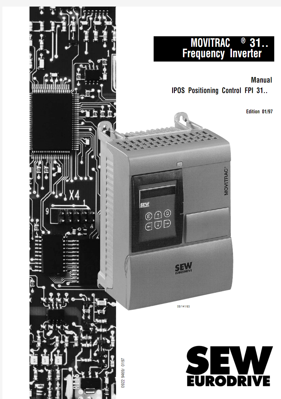
MOVITRAC ? 31..Frequency Inverter
Manual
IPOS Positioning Control FPI 31..
Edition 01/97
0922 9469 / 0197
q Read this manual carefully before you start installation and commissioning work on MOVITRAC?frequency inverters fitted with the IPOS(FPI31..)internal positioning control option.
This manual assumes that the user is familiar with and has at his disposal all relevant documentation on the MOVITRAC?31..system.
q Safety notes
Always follow the safety notes contained in this manual.
Safety notes are marked as follows:
q General safety notes for IPOS
The IPOS positioning control allows you to match the MOVITRAC?31..drive system to the
specifics of your application to a very high degree.As with all positioning systems there is,
however,the risk of a programming error in the program,which may result in unexpected(not
uncontrolled,though!)system behaviour.
q In these instructions, cross-references are marked with a→,e.g.,
(→MC_SHELL)means:Please refer to the MC_SHELL manual for detailed information or
information on how to carry out this instruction.
(→Sec. x.x) means:Further information can be found in section x.x of this manual.
q Each unit is manufactured and tested to current SEW-EURODRIVE technical standards and specifications.
The manufacturer reserves the right to make changes to the technical data and designs as well
as the user interface herein described, which are in the interest of technical progress.
A requirement of fault-free operation and fulfilment of any rights to claim under guarantee is that
these instructions and notes are followed.
These instructions contain important information for servicing,they should therefore be kept near
the unit.
Important Notes
2MOVITRAC?31.. - FPI31..
Page 1System Description (5)
2Installation (7)
2.1Connecting the cables and the encoder (7)
2.2Limit switch connection (7)
2.3Reference cam (7)
2.4Override connection (7)
3Commissioning (8)
3.1Activating the positioning control (8)
3.1.1Preliminary work (8)
3.1.2Connecting the positioning control (8)
3.1.3Important parameters for optimization (8)
4Machine Parameters (9)
4.1General (9)
4.2Machine parameter description (9)
4.2.1Timeout period (9)
4.2.2Reference offset (10)
4.2.3Reference speed 1 (10)
4.2.4Reference speed 2 (10)
4.2.5Reference travel type(see reference travel description) (10)
4.2.6Position controller gain (11)
4.2.7Positioning ramp (11)
4.2.8Positioning speed CW/CCW (11)
4.2.9PC position setpoint (11)
4.2.10Software limit switches CW/CCW (11)
4.2.11Position window (12)
4.2.12Override (12)
4.2.13Teach terminal (12)
4.2.14Lag error window (12)
4.2.15Travel distance indication (12)
4.2.16Travel distance factor numerator/denominator (12)
4.2.17Brake function (13)
4.2.18Brake reaction time (14)
4.2.19IPOS bus mode (14)
4.2.20Feedforward (14)
4.3Basic unit parameters important for IPOS (15)
5Working with IPOS (16)
5.1IPOS operating modes (16)
5.2Carry out reference travel (16)
5.2.1Types of reference travel (17)
5.3Manual mode (19)
5.3.1Reference axis (19)
5.3.2IPOS operating mode (20)
5.3.3Manual mode (20)
5.3.4Speed setpoint (20)
5.3.5Absolute position setpoint (20)
5.3.6Relative position setpoint (20)
5.3.7Travel parameters (20)
5.3.8Timeout period (20)
Contents
MOVITRAC?31..-FPI31..3
Contents
5.4Automatic mode (21)
5.4.1Automatic BREAKPOINT[F4] (21)
5.4.2Automatic HALT[F5] (21)
5.4.3Automatic STEP[F7] (21)
5.4.4Automatic STOP[F8] (21)
5.4.5Automatic RUN[F9] (21)
5.4.6Controller inhibit and enable function for IPOS (22)
5.5Limit switch processing (23)
5.5.1Hardware limit switches (23)
5.5.2Software limit switches (23)
6Fault Messages / Service Information (24)
6.1Status displays (24)
6.1.1Status window (24)
6.1.2Display window(“Process value”) (24)
6.2IPOS fault response (25)
6.2.1List of IPOS faults (25)
6.2.2Fault reset (25)
7Travel Programs (26)
7.1Programming travel programs (26)
7.1.1General IPOS programming rules (26)
7.2Program format (26)
7.3Loading/saving/editing programs (27)
7.4Entering programs (28)
7.5Set of commands (29)
7.5.1Overview (29)
7.6Detailed description (31)
7.6.1Positioning commands (31)
7.6.2Jump commands (33)
7.6.3Wait commands (36)
7.6.4Set commands (36)
7.6.5Variable commands (38)
7.6.6Teach commands (39)
7.6.7Touch probe commands (41)
7.6.8Miscellaneous commands (41)
8Application Notes (43)
8.1Hoist application (44)
8.1.1Schematic structure (44)
8.1.2Terminal assignment (45)
8.1.3Setting MC_SHELL parameters for IPOS applications (46)
8.1.4Calculating IPOS machine parameters (47)
8.1.5Hoist program (47)
8.2Sample program for jogging application (48)
9Index (49)
4MOVITRAC?31.. - FPI31..
System Description
1 1System Description
The IPOS positioning control provides point-to-point positioning with the MOVITRAC?31..frequency
inverter.
The IPOS positioning control offers the following features:
q Supports fieldbus operation and serial communications through the RS-485and RS-232 interfaces.
q Relieves the higher-level positioning control(e.g.PLC or IPC) from positioning tasks.
q Economizes on the use of proximity/limit switches compared to positioning by creep speed and use of brake and at the same increases the cycle rate.
q Position-controlled operation also for hoists and when at rest.
q Positioning by tables, a maximum of 32positions can be permanently stored.
q Teach-in mode.
q High positioning accuracy.
q Programming interface integrated into the MC_SHELL user interface.
Required system components:
q MOVITRAC?31..frequency inverter, sizes1,2,3 or4.
q FPI 31..option pcb,this also provides the encoder supply(5V).
q Incremental encoder(RS-422/TTL)with zero channel fitted onto the motor shaft.Pulses per revolution:128,256,512,1024,2048ppr,1024ppr are preferred.
q Frequency inverter capable of 4-quadrant operation.
Optional expansions (only one option possible at a time):
q Fieldbus interfaces
Profibus-DP and-FMS with FFP31..or Interbus-S with FFI31..
q Terminal expansion options(in addition to 4/2digital inputs/outputs in the basic unit)
–FEA 31..4/2 digital inputs/outputs, RS-485,analog functions
–FIO31..7/6 digital inputs/outputs, RS-485
Overview of drive structure:
The inverter uses the FPI31..to sense the signals from the incremental encoder as the basis for
determining speed and drive position.To specify an absolute reference point a reference travel must
be carried out.For this,6selectable strategies(reference travel types)are available,which,among
other things,determine in which direction of rotation the drive is going to search for the reference
point and which of the existing switches(reference cam,CCW/CW limit switch)is used.The limit
switches(CCW/CW)determine the limits of travel.The drive is brought to a stop using the rapid stop
ramp when approaching a limit switch.Depending on the type of reference travel,a limit switch may
also serve as a reversal switch.If the reference cam was not found,the search continues in the
opposite direction.
Fig. 1:System overview 00392AEN The CCW/CW limit switch is defined as the switch which is reached when the motor rotates counterclockwise (n)/clockwise (n0).Since the reference cam has a switching hysteresis,the zero pulse of the incremental feedback is evaluated to determine the reference point.Positioning procedure:When a travel command (GOWA #target position)is entered,a speed profile is generated.The drive then uses this speed profile,which is based on the specified travel parameters (machine parameters )positioning speed and positioning ramp,to approach the target position.Operating modes:q Automatic mode The IPOS program generated by the customer is processed cyclically in the inverter.A PC is required for commissioning and program generation. The drive is controlled by terminal signals or by fieldbus,depending on the degree of expansion.For drive diagnosis the MC_SCOPE user interface is available.q Manual mode The drive can be operated in manual mode from MC_SHELL without a positioning program,e.g.during the initial start up.A change between modes,i.e.between automatic and manual mode or between IPOS and speed control mode is only possible through MC_SHELL.System Description
1
operational approach to the limit switch during reference travel limit switch is used as reversing switch and search for the reference cam continues in the opposite direction Control signals Encoder zero channel Reference cam Speed (CW)Zero point CCW Zero point CW Fig.2: Zero pulse as reference point
00393AEN Position Speed Positioning speed Target position Fig.3:Speed and position characteristics 00394AEN 6MOVITRAC ?31.. - FPI 31..
2Installation
2.1Connecting the cables and the encoder
Both the input and output terminals X2/X3of the
basic unit and the input and output terminals X7/X8
of the FEA 31../FIO 31..option pcbs can be used.
The notes in the MOVITRAC ?Operating
Instructions regarding the encoder connection to
FPI 31..must be observed.Supported encoder systems are incremental
encoders with 128/256/512/1024/2048pulses per
revolution.Only use encoders which are fitted
directly onto the motor shaft.If the encoder is not
connected to the voltage supply of the FPI 31..,
terminals TL 94/95and TL 96/97must be
jumpered.
2.2Limit switch connection
All the programmable input terminals can be used as hardware limit switches for the positioning control.The limit switches must be normally closed.
Note:The correct limit switch allocation is always:
–Travel towards “CW limit switch”when motor speed ≥0!
–Travel towards “CCW limit switch”when motor speed ≤0!
A continuous signal must be ensured in the entire limit switch range!
The purpose of the hardware limit switches is to limit the travel.The range on and outside the limit switches cannot be used for operational travel.During the reference travel,the hardware limit switches act as reversing switches or reference cams,depending on the type of reference travel (→Sec.5.2,Reference travel).Approaching the limit switches during a reference travel does not cause a fault.
2.3Reference cam
Depending on the type of reference travel a reference cam (“normally open”)is required.The reference cam is used as point of reference for determining the drive position.
2.4Override connection
To enable a travel program to be run at a speed other than its programmed speed,a positive analog setpoint can be entered on terminals X2/34and X2/35.This allows the traveling speed to be set to a value between 0and 150%(applied to 0V and 10V)of the programmed speed (e.g.for set-up purposes).
The maximum speed is always limited by the values of parameters P202(FMAX)and P324(POLE PAIR NUMBER).Installation 2
Screen Encoder 5V TTL
X0:Fig.4: Wiring diagram for the FPI 31..00391AEN
MOVITRAC ?31..-FPI 31..7
3Commissioning
3.1Activating the positioning control
3.1.1Preliminary work
q Commission the inverter in accordance with the MOVITRAC?31..Installation and Operating Instructions in operating mode “V/f control”(parameter P770).
q Commission the inverter in accordance with the MOVITRAC?31..Installation and Operating Instructions in operating mode “Speed control”(parameter P770).
q Check the terminal assignment of the inverter when the inverter is in the“NO ENABLE”condition.
Program the input/output terminals required for positioning control(→Sec. 4.3).
Important:When the operating mode is set to“Positioning”(parameter P770)terminal X2.41is automatically permanently assigned with the function “/controller inhibit” signal.
q Check the limit switches and the emergency stop circuit.
q Set the machine parameters with MC_SHELL (→MC_SHELL manual).
3.1.2Setting the positioning control
q To set the operating mode to“Positioning”(P770)the inverter must not be enabled.
q The machine parameters must be set accordingly(see section4).
q Optimize the speed controller and position controller(see section3.1.3).
q Develop the position control
program.
3.1.3Important parameters for optimization
*)Observe setting instructions in the MOVITRAC?31.. Installation and Operating Instructions.
Commissioning
3
8MOVITRAC?31.. - FPI31..
4Machine parameters
4.1General
IPOS machine parameters can only be accessed through MC_SHELL (main menu IPOS),not with the FBG 31..keypad. The window for setting the machine parameters can be displayed by selecting the IPOS main menu.The most important settings for the positioning control mode can be entered and modified in this window.
To enable the use of input and output terminals in automatic mode, they must be set accordingly in the “Terminal assignment”menu (→Sec.4.3).The machine parameters are “normal”unit parameters and are thus transferred directly to the unit as they are changed and saved accordingly.Like all other parameters, they have a factory-set default value.
4.2Machine parameter description
4.2.1Timeout period
The timeout period is the time during which the transfer of data must take place between MOVITRAC ?and the PC (or a control system),otherwise the drive will be stopped using the rapid stop ramp.This monitoring function is only active in the IPOS operating mode “Manual”.
Range:0 (32767)
Factory setting:0(monitoring off).
Safety note
Timeout period monitoring ensures that if the link with the PC goes down,the drive stops when the timeout period has elapsed.This is particularly important if a speed or position setpoint is entered manually, but action via the PC is prevented by the failure of the link.It is always possible to switch off via the terminals as well.Machine Parameters
4
Fig.5:Machine parameter window
00358AEN MOVITRAC ?31..-FPI 31..9
Machine Parameters
4
4.2.2Reference offset
This value is added to the reference value to determine the machine zero.The following equation
applies:
Machine zero = reference point + reference offset.
As with all length data,this parameter is based on the unit specified by the user (see Sec. 4.2.16).
Factory setting:0.
4.2.3Reference speed1
Determines the speed for the reference travel.The direction of rotation is unambiguously identified
by the reference type.
Range:0to 5000rpm.
Factory setting:200rpm.
4.2.4Reference speed2
Determines the speed for traveling off the reference cam to the encoder zero pulse.The direction of
rotation is unambiguously identified by the reference type.
Range:0to 5000rpm.
Factory setting:50rpm.
4.2.5Reference travel type (see section
5.2)
The following are possible:
–Type 0:no reference travel
–machine zero =reference point+reference offset
–Type 1:CCW end of reference cam
–first search direction CCW
–machine zero =reference point+reference offset
–Type 2:CW end of reference cam
–first search direction CW
–machine zero =reference point+reference offset
–Type 3:CW limit switch
–first search direction CW
–machine zero =reference point+reference offset
–Type 4:CCW limit switch
–first search direction CCW
–machine zero =reference point+reference offset
–Type 5:no reference travel
–machine zero =reference offset
Note:This parameter must not be changed whilst a reference travel is being performed (fault 61)!
Factory setting:type0.
10MOVITRAC?31.. - FPI31..
Machine Parameters
4
4.2.6Position controller gain
Value for the P controller of the position control loop.The value can be optimized with MC_SCOPE
in conjunction with the speed controller.
Range:0.1to 60.
Factory setting:0.5.
4.2.7Positioning ramp
Value for the ramp time during the positioning process.The standard ramps(P12_,P13_)are not
effective.The same ramp is used for both acceleration and deceleration.The value represents a time
to ramp the drive from 9to 3000rpm.
Range:0to 0.5s→0.02;0.5to3 s→0.1;3 to 10s→0.5.
Factory setting:2s.
4.2.8Positioning speed CW/CCW
These two parameters determine the positioning speed in the positive direction(n>0)/in the negative
direction(n<0).
The value is entered in revolutions per minute and must be matched to the maximum motor speed.
Range:0to 5000rpm.
Factory setting:1500rpm.
Note:Parameters202(pole pair number)and324(f max)limit these machine parameters(max.120Hz)!
P202?60
n max=
P324
4.2.9PC position setpoint
Can be used at any point within the automatic program with the GOPA command.The value is entered
in MC_SHELL in user units and via the communications interfaces in increments.The parameter
value is not stored when the unit is powered down.
Range:-231to +231increments.
Factory setting:0.
4.2.10Software limit switches CW/CCW
These two parameters determine the limits of travel.In the automatic mode they ensure that the drive
does not go to a target position outside the limits of travel.If the target position lies outside the limits
of travel,the drive immediately decelerates using the rapid stop ramp and generates a fault message.
To clear a fault after approaching a software limit switch refer to section5.5.In the case of reference
travel types 3and4the corresponding software limit switch must be set to the position value of the
hardware limit switch used as reference cam.For uni-directional operation both values must be set
to0.The value is entered in MC_SHELL in user units and via the communications interfaces in
increments.
Range:-231to +231increments.
Factory setting:0(Monitoring of the software limit switches deactivated).
Note:Monitoring of the software limit switches is only effective after a reference travel.
4.2.11Position window This parameter is used to indicate when the target position has been reached.This is done by continuously comparing the absolute difference between actual position and target position.If this difference is less than the value specified for the position window then the axis is considered “In position”,and an output assigned with the function “Axis in position”is set high.Range:0to 215increments.Factory setting:50.Note:If the brake function is activated,the position window value must be greater than the brake tolerance.4.2.12Override Switches the override function ON and OFF (see Override connection,Sec. 2.4).4.2.13Teach terminal This parameter determines which of the physical input terminals (basic unit or FEA 31../FIO 31..)is
Range:1to 10.Factory setting:2.4.2.14Lag error window The lag error window is the maximum permissible difference between target position and actual positions.If this is exceeded,a lag error occurs.The motor is brought to a stop using the rapid stop ramp. Lag error monitoring is deactivated if this parameter is set to 0.Unit:increments.Range:0to 231increments.Factory setting:5000.4.2.15Travel distance indication Five-digit character string for the user-defined length units.These are freely selectable and are stored in the unit.In the manual mode window,the machine parameter window and in the positioning program,all length entries will be shown with this symbolic description.Note:This parameter has no travel-specific effect.4.2.16Travel distance factor numerator/denominator These parameters are used to convert user length units into incrementals.IPOS always operates internally with 4096incr./revolution,regardless of the number of pulses of the incremental encoder.The general conversion equation is:travel distance factor numerator x IPOS [increments]=?x command
[travel distance indication]travel distance factor denominator The numerator represents the number of increments per output shaft revolution,the denominator represents the traveled distance per revolution in user units.Range:0to 231.Factory setting:1.Machine Parameters
412MOVITRAC ?31.. - FPI 31..
Example:The drive shown below (bottling application)is to be programmed in the following units:a)mm in the linear axis
b)increments
c)output revolutions
d)bottles (3bottles / 400mm)
Solutions:
a)User distance units =mm
Travel factor numerator =(4096·gear ratio i)·reduction factor =4096·5 ·1000= 20480000Travel factor denominator = (d output ·π)·reduction factor =100·π·1000=314159
Note :The conversion can be made more accurate if the numerator and denominator are multiplied by a factor to eliminate the decimal portion (only required if numerator or denominator are not integers).This does not limit the maximum travel range.The travel distance factors are stored in the axis, the conversion is carried out by the PC operator routine.
b)User distance units =incr.
Travel distance factor numerator =1
Travel distance factor denominator = 1
c)User distance units =rev.
Travel distance factor numerator =4096·gear ratio =4096·5= 20480
Travel distance factor denominator = 1
d)User distance units =bot.
Travel distance factor numerator =(4096·gear ratio i)·400(mm) ·reduction factor
=4096·5 ·1000= 8192000000
Travel distance factor denominator = d ·π·3(bot)·reduction factor =100·π·3 ·1000=942477
4.2.17Brake function
This function supports control of a mechanical motor brake in positioning mode.If the brake function is activated,the brake reaction time is taken into account when stopping and starting.The brake output X3.61and the output stage are then controlled appropriately.
Note:The brake function can be switched on and off by a command in the automatic program (→Sec. 7.6.8).If the brake function is used,the position window must be larger than the tolerance of the mechanical brake (to take the backlash of the brake carrier and the brake pad into account).Machine Parameters 4
Motor Encoder
Gear ratio = 5
Drive d = 100 mm x [mm]
Fig. 6:Example for programming units
00395AEN MOVITRAC ?31..-FPI 31..13
Response of the axis with braking function on:The brake function is always effective if IPOS is being operated in position controller mode (and the function is activated). This will be the case in automatic mode and manual mode/position control.The brake will always be released in manual mode/speed control!4.2.18Brake reaction time This parameter allows for programming of the brake reaction time of the mechanical brake.4.2.19IPOS bus mode This parameter enables IPOS to be controlled via a fieldbus interface and determines how a position setpoint transmitted via fieldbus is evaluated.
In IPOS bus mode =2→the position setpoint is stored in variable 254and can be further processed in the program.Range:0to 3.Factory setting:0.4.2.20Feedforward With a value of 100%,the drive operates with a linear speed profile optimized to respect of time,minimizing the difference between setpoint speed and actual speed.If a value less than 100%is specified,a gap between setpoint position and actual position occurs (lag distance)during a positioning
operation.This results in a “soft”run-in to the target position.Range:-150%to +150%.Factory setting:100%.The lower the value is set,the sooner it trips the axis with a lag error (F42).The lowest possible setting depends on the required dynamics of the system.Machine Parameters 41
1t n (t)
setp /Brake signal Output stage enable Brake reaction time and pre-/postmagnetization time Automatic command: "Position to X1 wait""Wait t1""Position to X2 wait"Fig. 7:Brake function 00396AEN 14MOVITRAC ?31.. - FPI 31..
Machine Parameters
4 4.3Basic unit parameters important for IPOS
Menu item770:operating mode
Set to Positioning.
Menu item140:rapid stop ramp
This ramp is used in conjunction with the STOP command or if the enable signal is removed.It
is further used during the entire reference travel and for fault response.
Menu item777:feedforward gain and778:feedforward filter
The setting is the same as for the speed control (→MOVITRAC?31..Installation and Operating
Instructions).
Menu item324:pole pair number and202: F max(max. 120Hz )
These values limit the machine parameters”Positioning speed CW/CCW”.The speed value
resulting from these parameters should always be larger than the desired positioning speed
(otherwise a lag error may occur).
P202?60
f max=
P324
Menu item323:slip
This parameter should be set based on general commissioning data.
Menu items600to 606:binary inputs on basic unit and FEA31../FIO 31..
The input terminals initially have the functions and characteristics as described in the MOVITRAC?
31..Installation and Operating Instructions.In addition,IPOS allows the functions“/limit switch
CW”,“/Limit switch CCW”,“Reference cam”and“Reference travel”to be programmed to the
input terminals.Input terminals,which are used in the IPOS automatic program exclusively must
be programmed with“No function”.To use them in the automatic program,a“1”must be entered
in the respective positions in the selection masks for the individual commands.
The following IPOS commands are possible:
–wait until terminals are 1 or0,
–jump if terminals are1or0,
–selection of table positions with terminals,
–teach function,
–setting terminals
Menu items611to 613:binary outputs on basic unit and FEA31../FIO 31..
Functions that are used in conjunction with IPOS:
–axis in position,
–8freely programmable binary outputs of which3can be physically implemented with FEA31..
and
7 with FIO31...
Output terminals,which are used in the IPOS automatic program exclusively must be programmed
with “Output IPOS x”.(x =1 ...8).
Working with IPOS
5
5Working with IPOS
5.1IPOS operating modes
The following operating modes are available in IPOS:
–reference travel (see Sec. 5.2)
–manual mode (see Sec. 5.3)
–manual mode speed control
–manual mode position control
–automatic mode (see Sec. 5.4)
–automatic STOP
–automatic RUN
–automatic STEP
–automatic BREAKPOINT
–automatic HALT
5.2Carry out reference travel
Referencing provides a way of determining a machine zero to which all positioning commands refer.
To ensure that positioning operations remain constant over many years it must be possible to define
this point most precisely and with a high repeat accuracy.
Since the reference cam has a switching hysteresis,the nearest zero pulse of the encoder system is
used as a reference point.Whether this is the CW or the CCW one is determined by the reference
travel type.Once the reference point is known,the machine zero(actual reference point for all
positioning commands)can be determined based on the reference point.The following applies: Machine zero= reference point +reference offset
The reference cam must be normally open.The first search direction is determined by the type of
reference travel.During reference travel,the limit switches act as“reversing switches”.When the
reference travel is completed,the drive remains position controlled in the position“machine zero”.
The rapid stop ramp is used during the entire reference travel(necessary to ensure rapid change of
the various reference speeds).
Note:
The reference cam must be wide enough to ensure unambiguous behaviour for the appropriate
reference travel types and the specified reference speeds together with the rapid stop ramp(important
for types1 and2).
16MOVITRAC?31.. - FPI31..
5.2.1Types of reference travel
Explanation of the reference travel type diagrams
Possible starting points for the drive:
drive is located between reference cam and CW limit switch
drive is located on the reference cam
drive is located between reference cam and CCW limit switch
Explanation of the abbreviations in the diagrams:
CW LS CW hardware limit switch (positive limit switch)
CCW LS CCW hardware limit switch (negative limit switch)
ref cam reference cam
NP zero pulse ?reference point
Vref1initial reference travel speed
Vref2final reference travel speed to approach the zero pulse of the encoder.
Type 0:Reference point is the first zero pulse CCW to the current position.
machine zero =zero pulse CCW to rotor position + reference offset
Note:Only when the command GOWA (#0)is given,does the drive travel to the machine zero (v ref2).Type 1:Reference point is the first zero pulse CCW to the reference cam
machine zero =reference point (NP)+ reference offset Working with IPOS 5Reference offset
Machine zero LS CCW LS CW
NP
Vref2
Current position
of the drive
Fig.8:Reference travel type 000397AEN 32
1
Vref1
Vref2LS CCW LS CW
NP Refcam Fig.9:reference travel type 1MD0066AE MOVITRAC ?31..-FPI 31..17
Type 2:Reference point is the first zero pulse CW to the reference cam machine zero = reference point (NP) +reference offset Type 3:Reference point is the first zero pulse CCW to the CW limit switch machine zero = reference point (NP) +reference offset Reference cam is not required.Type 4:Reference point is the first zero pulse CW to the CCW limit switch machine zero = reference point (NP) +reference offset Reference cam is not required.Type 5:No reference travel:machine zero =reference offset Note:Reference travel must also be initiated for reference travel type 5.Working with IPOS
5123Vref1Vref2LS CCW LS CW NP Ref. cam Fig.10:Reference travel type 2MD0067AE 321Vref1Vref2LS CCW LS CW NP Ref. cam Fig.11:Reference travel type 300398AEN 123Vref1Vref2LS CCW LS CW NP Ref. cam Fig. 12:Reference travel type 4
00399AEN Reference offset machine zero LS CCW LS CW NP Current position of the drive Fig.13:Reference travel type 500018AEN 18MOVITRAC ?31.. - FPI 31..
Reference travel can be initiated in the following ways:
q By programming an input terminal (basic unit or FEA 31../FIO 31..)with the “REFERENCE TRAVEL”function. When the signal goes high,the reference travel is performed according to the selected reference travel type.
q By a GO?command in the automatic program.
q By making an entry in the manual mode window.
Once started,a reference travel will be completed even if the initiating signal is no longer there.The reference travel procedure is interrupted when the enable signal goes low and cancelled if the inhibit signal goes low.An axis that is already referenced can only be referenced again from the manual mode window or with the GO?#1command in the automatic https://www.360docs.net/doc/a22015991.html,pletion of the reference travel is indicated in the status window.
5.3Manual mode
Manual mode can be initiated by opening the manual mode window (IPOS main menu).The operating mode (parameter P770)must be set to “Positioning”.
The upper part of the manual mode window provides status information on the axis. The lower part contains the control features used for manual operation of the axis.
A TEACH FUNCTION allows for the argument (distance)of a GO-command in the automatic program to be set to the position which has been approached in manual mode.To do this,highlight the travel command in the automatic program with the cursor bar.Click on the TEACH button or press the ALT +F9keys to get to the manual mode window.You can either “teach”the actual position or travel to the required postion.Press the ESC key and then confirm with RETURN to set the highlighted travel command with this position.
5.3.1Reference axis
The axis carries out a reference travel according to the selected machine parameters.A referenced axis can be referenced again with this menu item. If a value not equal to zero is entered in “position setpoint absolute”,the drive will travel to this position upon completion of the reference travel.When the referece travel is completed,this is indicated in the status section of this window.Working with IPOS
5
Fig. 14:Manual mode window
00359AEN MOVITRAC ?31..-FPI 31..19
5.3.2IPOS operating mode Select “Manual mode” to operate the drive manually.5.3.3Manual mode Specifies whether the axis is operated in speed control (n control)or position control (x control)mode.According to the setting,the n-setpoint or the x-setpoint will be used.The positioning ramp (machine parameters)is used in both settings.If the drive is operated in position control,the specified traveling speeds are used.5.3.4Speed setpoint This value is used as a speed setpoint if manual mode “speed control”is selected.The value is activated and weighted by operating the buttons -100%to +100%.If the buttons are not used,the default setpoint = 0is used.5.3.5Absolute position setpoint The value is entered in user distance units (Machine parameters →Sec. 4)and used as an absolute target position if confirmed with the ENTER key.The selected travel parameters will be used.5.3.6Relative position setpoint The value is entered in user distance units (→Machine parameters,Sec.4)and added to the current position value if it is confirmed with the ENTER key. The selected travel parameters will be used.5.3.7Travel parameters The parameters travel speed CW,travel speed CCW,positioning ramp are described in the machine parameters section (→Sec. 4).5.3.8Timeout period If the serial link goes down,the axis executes a rapid stop after the specified timeout period has elapsed.A timeout does not cause a unit trip.Note :If a value of 0is entered,timeout monitoring is switched OFF.In this case the setpoint transmission is not monitored and an interruption of the PC-MOVITRAC ?31..serial link is not recognized.Safety note Timeout period monitoring ensures that the drive stops after this period if the PC link goes down.This is of particular importance if a speed or position setpoint is entered in manual mode,but intervention from the PC is not possible as a result of the link going down.It is in any case always possible to switch off via the terminals.Working with IPOS
520MOVITRAC ?31.. - FPI 31..
步进电机控制器--说明书[1].答案
步进电机,伺服电机可编程控制器KH-01使用说明 一、系统特点 ●控制轴数:单轴; ●指令特点:任意可编程(可实现各种复杂运行:定位控制和非定位控制); ●最高输出频率:40KHz(特别适合控制细分驱动器); ●输出频率分辨率:1Hz; ●编程条数:99条; ●输入点:6个(光电隔离); ●输出点:3个(光电隔离); ●一次连续位移范围:—7999999~7999999; ●工作状态:自动运行状态,手动运行状态,程序编辑状态,参数设定状态; ●升降速曲线:2条(最优化); ●显示功能位数:8位数码管显示、手动/自动状态显示、运行/停止状态显示、步数/计数值/程序显示、编辑程序,参数显示、输入/输出状态显示、CP脉冲和方向显示; ●自动运行功能:可编辑,通过面板按键和加在端子的电平可控制自动运行的启动和停止; ●手动运行功能:可调整位置(手动的点动速度和点动步数可设定); ●参数设定功能:可设定起跳频率、升降速曲线、反向间隙、手动长度、手动速度、中断跳转行号和回零速度; ●程序编辑功能:可任意插入、删除可修改程序。具有跳转行号、数据判零、语句条数超长和超短的判断功能; ●回零点功能:可双向自动回到零点; ●编程指令:共14条指令; ●外操作功能:通过参数设定和编程,在(限位A)A操作和(限位B)B操作端子上加开关可执行外部中断操作; ●电源:AC220V(电源误差不大于±15%)。
一、前面板图 前面板图包括: 1、八位数码管显示 2、六路输入状态指示灯 3、三路输出状态指示灯 4、 CP脉冲信号指示灯
5、 CW方向电平指示灯 6、按键:共10个按键,且大部分按键为复合按键,他们在不同状态表示的功能不同,下面的说明中,我们只去取功能之一表示按键。 后面板图及信号说明: 后面板图为接线端子,包括: 1、方向、脉冲、+5V为步进电机驱动器控制线,此三端分别连至驱动器的相应端,其中: 脉冲————步进脉冲信号 方向————电机转向电平信号 +5V————前两路信号的公共阳端 CP、CW的状态分别对应面板上的指示灯 2、启动:启动程序自动运行,相当于面板上的启动键。 3、停止:暂停正在运行的程序,相当于面板上的停止键,再次启动后,程序继续运行。 4、 (限位A)A操作和(限位B)B操作是本控制器的一大特点:对于步进电机,我们一般进行定量定位控制,如控制电机以一定的速度运行一定的位移这种方式很容易解决,只需把速度量和位移量编程即可。但还有相当多的控制是不能事先定位的,例如控制步进电机从起始点开始朝一方向运行,直到碰到一行程开关后停止,当然再反向运行回到起始点。再例如要求步进电机在两个行程开关之间往复运行n次,等等。在这些操作中,我们事先并不知道步进电机的位移量的具体值,又应当如何编程呢?本控制器利用:“中断操作”,我们称之为“(限位A)A操作”和“(限位B)B操作”。以“(限位A)A操作”为例,工作流程为:当程序在运行时,如果“(限位A)A 操作”又信号输入,电机作降速停止,程序在此中断,程序记住了中断处的座标,程序跳转到“(限位A)A操作”入口地址所指定的程序处运行程序。 5、输入1和输入2通过开关量输入端。 6、输出1、输出2和输出3通过开关量输出端。 7、+24V、地—输入输出开关量外部电源,本电源为DC24V/0.2A,此电源由控制器内部隔离提供。 8、 ~220V控制器电源输入端。 输入信号和输出信号接口电路: 本控制器的“启动”、“停止”、“(限位A)A操作”、“(限位B)B操作”、“输入1”、“输入2”为输入信号,他们具有相同的输入接口电路。“输出1”、“输出2”、“输出3”称为输出信号。他们具有相同的输出接口电路。输入和输出电路都有光电隔离,以保证控制器的内部没有相互干扰,控制器内部工作电源(+5V)和外部工作电源(+24V)相互独立,并没有联系,这两组电源由控制器内部变压器的两个独立绕组提供。 开关量输入信号输出信号的状态,分别对应面板上的指示灯。对于输入量,输入低电平(开关闭合时)灯亮,反之灯灭;对于输出量,输出0时为低电平,指示灯灭,反之灯亮。 开关量输入电路:
新力川伺服驱动使用说明
感谢您使用本产品,本使用操作手册提供LCDA系列伺服驱动器的相关信息。内容包括: ●伺服驱动器和伺服电机的安装与检查 ●伺服驱动器的组成说明 ●试运行操作的步骤 ●伺服驱动器的控制功能介绍与调整方法 ●所有参数说明 ●通讯协议说明 ●检测与保养 ●异常排除 ●应用例解说 本使用操作手册适合下列使用者参考: ●伺服系统设计者 ●安装或配线人员 ●试运行调机人员 ●维护或检查人员 在使用前,请您仔细详读本手册以确保使用上的正确。此外,请将它妥善保存在安全的地点以便随时查阅。下列在您尚未读完本手册时,务必遵守事项: ●安装的环境必须没有水气,腐蚀性气体或可燃性气体。 ●接线时,禁止将三相电源接至马达U、V、W的连接器,因为一旦接错 时将损坏伺服驱动器。 ●接地工程必须确实实施。 ●在通电时,请勿拆解驱动器、马达或更改配线。 ●在通电动作前,请确定紧急停机装置是否随时开启。 ●在通电动作时,请勿接触散热片,以免烫伤。 如果您在使用上仍有问题,请洽询经销商或者本公司客服中心。
安全注意事项 LCDA 系列为一开放型(Open Type )伺服驱动器,操作时须安装于遮蔽式的控制箱内。本驱动器利用精密的回授控制与结合高速运算能力的数字信号处理器(Digital Signal Processor,DSP ),控制IGBT 产生精确的电流输出,用来驱动三相永磁式同步交流伺服马达(PMSM )达到精准定位。 LCDA 系列可使用于工业应用场合上,且建议安装于使用手册中的配线(电)箱环境(驱动器、线材与电机都必须安装于符合环境等级的安装环境最低要求规格)。 在按收检验、安装、配线、操作、维护与检查时,应随时注意以下安全注意事项。 标志[危险]、[警告]与[禁止]代表的含义: ? 意指可能潜藏危险,若未遵守要求可能会对人员造成严 重伤或致命 ? 意指可能潜藏危险,若未遵守可能会对人员造成中度的 伤害,或导致产品严重损坏,甚至故障 ? 意指绝对禁止的行动,若未遵守可能会导致产品损坏, 或甚至故障而无法使用
DA98伺服驱动器说明书
第一章概述 1.1 产品简介: 交流伺服技术自九十年代初发展至今,技术日臻成熟,性能不断提高,现已广泛应用于数控机床、印刷馐机械、纺织机械、自动化生产线等自动化领域。 DDA98交流伺服系统系国产第一代全数字交流伺服系统,采用国际最新数字信号处理DSP)、大规模可编程门阵列(CPLD)和MISUBISHI智能化功率模块(IPM),集成度高、体积小、保护完善、可靠性好、彩最何必PID算法完成PWM控制,性能已达到国外同类产品的水平。 与步进系统相比,DA98交流伺服系统具有以下优点 ●避免失步现象 伺服电机自带编码器,位置信号反馈至伺服 驱动器,与开环位置控制器一起构成半闭环 控制系统。 ●宽速比、恒转矩 调速比为1:5000,从低速到高速都具有稳 定的转矩特性。 ●高速度、高精度 伺服电机最高转速可达3000rpm,回转定位 精度1/10000r。 〖注〗不同型号伺服电机最高转速不同。 ●控制简单、灵活 通过修改参数可对伺服系统的工作方式、运 行特性作出适当的设置,以适应不同的要求。
1.2 到货检查 1)收货后,必须进行以下检查: (1) 包装箱是否完好,货物是否因运输受损? (2) 核对伺服驱动器和伺服电机铭牌,收到货物是否确系所订货物? (3) 核对装箱单,附件是否齐全? 2)型号意义: (1) 伺服驱动器型号 (示出华中理工大学电机厂STZ 系列) ※1 (04、06……23)对应0.4~2.3KW ※2 ※1:可选配其它国产、进口伺服电机,需订货。驱动器缺省参数仅适配STZ 系列伺服电机, 选配其它伺服电机时,出厂参数已备份在EEPROM 区。恢复出厂参数时应执行恢复备份,不可执行恢复缺省参数操作。 ※2:中小功率(小于等于1.5KW )为标准配置,中功率(大于1.5KW 、小于等于2.3KW )采用 加厚散热器。 〖注〗产品出厂时,上面填写框已按产品型号填写好,请用户与产品铭牌核对。 (2) 伺服电机型号 DA98交流伺服驱动器可与国内外多款伺服电机配套,由用户订货时选择。本手册按华中电机厂生产的伺服电机进行描述,其它型号伺服电机有关资料随伺服电机提供。 光电编码器反馈 电机工作电压H :300V L :200V 额定转速级别 1:低速(1500/2000rpm ) 2:高速(2500/3000rpm ) 零速转矩2、4、5、6、7.5、10…N.m 正弦波驱动伺服电机 电机外径 110:110×110mm 130:130×130mm
安川伺服电机说明书
YSKAWA 安川∑Ⅱ数字交流伺服 安装调试说明书 (2004.7版本)
目 录 1. 安川连接示意图 2. 通电前的检查 3. 通电时的检查 4. 安川伺服驱动器的参数设定 5. 安川伺服驱动器的伺服增益调整
1. 安川连接示意图 重要提示: 由于电机和编码器是同轴连接,因此,在电机轴端安装带轮或连轴器时,请勿敲击。否则,会损坏编码器。(此种 情况,不在安川的保修范围!)
2. 通电前的检查 1) 确认安川伺服驱动器和电机插头的连接,相序是否正确: A.SGMGH电机,不带刹车制动器的连接: 伺服驱动器 电机插头 U A V B W C 接地 D B.SGMGH电机 0.5KW-4.4KW,带刹车制动器电机的连接: 伺服驱动器 电机插头 U A V B W C 接地 D 刹车电源 E 刹车电源 F 刹车电源为: DC90V (无极性) C. SGMGH电机5.5KW-15KW,带刹车制动器电机的连接: 伺服驱动器 电机插头 U A V B W C 接地 D 电机制动器插头 刹车电源 A 刹车电源 B 刹车电源为: DC90V (无极性) 注: 1.相序错误,通电时会发生电机抖动现象。 2.相线与“接地”短路,会发生过载报警。
2)确认安川伺服驱动器CN2和伺服电机编码器联接正确, 接插件螺丝拧紧。 3)确认伺服驱动器CN1和数控系统的插头联接正确, 接插件螺丝拧紧。 3.通电时的检查 1) 确认三相主电路输入电压在200V-220V范围内。 建议用户选用380V/200V的三相伺服变压器。 2)确认单相辅助电路输入电压在200V-220V范围内。 4.安川伺服驱动器的参数设定 安川伺服驱动器参数,操作方法如下:(1)参数密码设定; (2)用户参数和功能参数的设定; 1)参数密码设定 为防止任意修改参数,将“Fn010”辅助功能参数,设定: ? “0000” 允许改写 PnXXX 的用户参数,及部分辅助功 能“FnXXX”参数。 ? “0001” 禁止改写 PnXXX 的用户参数,及部分辅助功 能“FnXXX”参数。
da9伺服驱动器说明书
第一章 概述 1.1 产品简介: 交流伺服技术自九十年代初发展至今,技术日臻成熟,性能不断提高,现已广泛应用于数控机床、印刷馐机械、纺织机械、自动化生产线等自动化领域。 DDA98交流伺服系统系国产第一代全数字交流伺服系统,采用国际最新数字信号处理DSP )、大规模可编程门阵列(CPLD )和MISUBISHI 智能化功率模块(IPM ),集成度高、体积小、保护完善、可靠性好、彩最何必PID 算法完成PWM 控制,性能已达到国外同类产品的水平。 与步进系统相比,DA98交流伺服系统具有以下优点 ● 避免失步现象 伺服电机自带编码器,位置信号反馈至伺服 驱动器,与开环位置控制器一起构成半闭环 控制系统。 ● 宽速比、恒转矩 调速比为1:5000,从低速到高速都具有稳 定的转矩特性。 ● 高速度、高精度 伺服电机最高转速可达3000rpm , 回转定位 精度1/10000r 。 〖注〗不同型号伺服电机最高转速不同。 ● 控制简单、灵活 通过修改参数可对伺服系统的工作方式、运 行特性作出适当的设置,以适应不同的要求。 1.2 到货检查 1)收货后,必须进行以下检查: (1) 包装箱是否完好,货物是否因运输受损? (2) 核对伺服驱动器和伺服电机铭牌,收到货物是否确系所订货物? (3) 核对装箱单,附件是否齐全? 2)型号意义: (1) 伺服驱动器型号 DA98
适配伺服电机型号(示出华中理工大学电机厂STZ 系列) ※1 输出功率:两位数字(04、06……23)对应0.4~2.3KW ※2 系列代号 ※1:可选配其它国产、进口伺服电机,需订货。驱动器缺省参数仅适配STZ 系列伺服电机, 选配其它伺服电机时,出厂参数已备份在EEPROM 区。恢复出厂参数时应执行恢复备份,不可执行恢复缺省参数操作。 ※2:中小功率(小于等于1.5KW )为标准配置,中功率(大于1.5KW 、小于等于2.3KW )采用加 厚散热器。 〖注〗产品出厂时,上面填写框已按产品型号填写好,请用户与产品铭牌核对。 (2) 伺服电机型号 DA98交流伺服驱动器可与国内外多款伺服电机配套,由用户订货时选择。本手册按华中电机厂生产的伺服电机进行描述,其它型号伺服电机有关资料随伺服电机提供。 STZ —— HM 3(1DA98伺服驱动器标准附件安装使用手册(本书)1本 安装支架2个 ×8沉头螺钉 4个 插头(DB25孔) 1套 (注1) 插头(DB25针) 1套 (注2) 〖注1〗 配套我厂位置控制器时,与信号电缆(3)米配套提供。 〖注2〗 我厂提供伺服电机时,用户可选择反馈电缆(3米)配套提供。 (2)伺服电机标准附件按伺服电机说明书提供 1.3 产品外观 1) 伺服驱动器外观 2) 伺服电机外观 第二章 安装 光电编码器反馈 电机工作电压H :300V L :200V 额定转速级别 1:低速(1500/2000rpm ) 2:高速(2500/3000rpm ) 零速转矩2、4、5、6、7.5、10…N.m 正弦波驱动伺服电机 电机外径 110:110× 110mm 130:130×130mm
交流伺服电机驱动器使用说明书.
交流伺服电机驱动器使用说明书 1 ?特点 16位CPU+32位DSP三环(位置、速度、电流)全数字化控制脉冲序列、速度、转矩 多种指令及其组合控制 转速、转矩实时动态显示 完善的自诊断保护功能,免维护型产品交流同步全封闭伺服电机适应各种恶劣环境体 积小、重量轻 2 ?指标 输入电源三相200V -10%?+15% 50/60HZ 控制方法IGBT PWM(正弦波) 反馈增量式编码器(2500P/r ) 控制输入伺服-ON报警清除CW、CCW驱动、静止 指令输入输入电压土10V 控制电源DC12?24V 最大200mA 保护功能OU LU OS OL OH REG OC ST CPU 错误,DSP错误,系统错误 通讯RS232C 频率特性200Hz或更高(Jm=Jc时)体积L250 X W85 X H205 重量3.8Kg 3?原理 见米纳斯驱动器方框图(图1)和控制方框图(图2) 4?接线 4.1主回路 卸下盖板坚固螺丝;取下端子盖板。用足够线经和连接器尺寸作连接,导线应采用额定温度600C以上的铜体线,装上端子盖板,拧紧盖板螺丝。螺丝拧紧力矩大于 1.2Nm M4或 2.0 Nm M5时才可能损坏端子,接地线径为2.0mn i 具体见接线图3 4.2CN SIG 连接器[ 具体见接线图4 驱动器和电机之间的电缆长度最大20M 这些线至少要离开主电路接线30cm,不要让这些线与电源进线走一线槽; 或让它们捆扎在一起 线经0.18mm2或以上屏蔽双绞线,有足够的耐弯曲力 屏蔽驱动器侧的屏蔽应连接到CN.SIG连接器的20脚,电机侧应连接到J 脚 若电缆长于10M,则编码器电源线+5V、0V应接双线 4.3CN I/F 连接 控制器等周边设备与驱动器之间距离最大为3M 这些线至少和主电路接线相隔30cm ,不要让这些线与电源进线走同一线槽 或和它们捆扎在一起 COM和COM之间的控制电源(V DC)由用户供给 控制信号输出端子可以接受最大24V或50mA不要施加超过此限位的电压 和电流 若用控制信号直接使继电器动作要象左图所示那样,并联一只二极管到继电 器。不接二极管或接错了二极管的极性,都将可能损坏驱动器 机身接地点(FG)要接到驱动器的一个接地端子具体见接线图5 5.参数
交流伺服电机驱动器使用说明书.
交流伺服电机驱动器使用说明书 1.特点 ●16位CPU+32位DSP三环(位置、速度、电流)全数字化控制 ●脉冲序列、速度、转矩多种指令及其组合控制 ●转速、转矩实时动态显示 ●完善的自诊断保护功能,免维护型产品 ●交流同步全封闭伺服电机适应各种恶劣环境 ●体积小、重量轻 2.指标 ●输入电源三相200V -10%~+15% 50/60HZ ●控制方法IGBT PWM(正弦波) ●反馈增量式编码器(2500P/r) ●控制输入伺服-ON 报警清除CW、CCW驱动、静止 ●指令输入输入电压±10V ●控制电源DC12~24V 最大200mA ●保护功能OU LU OS OL OH REG OC ST CPU错误,DSP错误,系统错误 ●通讯RS232C ●频率特性200Hz或更高(Jm=Jc时) ●体积L250 ×W85 ×H205 ●重量 3.8Kg 3.原理 见米纳斯驱动器方框图(图1)和控制方框图(图2) 4.接线 4.1主回路 卸下盖板坚固螺丝;取下端子盖板。用足够线经和连接器尺寸作连接,导线应采用额定温度600C以上的铜体线,装上端子盖板,拧紧盖板螺丝。螺丝拧紧力矩大于1.2Nm M4或2.0 Nm M5时才可能损坏端子,接地线径为2.0mm2 具体见接线图3 4.2 CN SIG 连接器[ 具体见接线图4 ●驱动器和电机之间的电缆长度最大20M ●这些线至少要离开主电路接线30cm,不要让这些线与电源进线走一线槽; 或让它们捆扎在一起 ●线经0.18mm2或以上屏蔽双绞线,有足够的耐弯曲力 ●屏蔽驱动器侧的屏蔽应连接到CN.SIG 连接器的20脚,电机侧应连接到J 脚 ●若电缆长于10M,则编码器电源线+5V、0V应接双线 4.3 CN I/F 连接 ●控制器等周边设备与驱动器之间距离最大为3M ●这些线至少和主电路接线相隔30cm ,不要让这些线与电源进线走同一线槽 或和它们捆扎在一起 ●COM+和COM-之间的控制电源(V DC)由用户供给
派克伺服电机M系列使用手册
?Size 16 and 23?0.8 to 11.3 in-lb.continuous torque ?Slotless design ?Rugged housing (IP65 option) ?Connection options SM Series SE Series ?Size 16 and 23?0.8 to 10.1 in-lb.continuous torque ?Slotless design ?Plastic encoder cover ?Short package length BE Series ?Size 16, 23 and 34? 1.4 to 46 in-lb. contin-uous torque ?Bridged stator design ?2000-line encoder standard ?Connection options NeoMetric & J Series ?70 mm and 92 mm ? 6 to 61 in-lb. contin-uous torque ?Bridged stator design ?Rugged housing (IP65 option) ? Connection options ?Size 16, 23, 34 and 92?Integrated pinion design ? Shortest package length available Planetary Gearheads SL Series M Series A Full Line Up of Powerful Servos to Meet the Demands of Your Application! Compumotor began manufacturing brushless servo motors with the release of the SM series in the spring of 1995. Since that time, we have continued to expand our product offering and have manufacturing plants in California and Italy. Innovation in Design Compumotor utilizes two distinct technologies in the manufacturing of brushless servo motors. The Slotless Design and the Bridged Stator Design both reduce motor manufacturing costs while providing performance advantages to the user. The slotless design eliminates all detent torque in the motor,providing superior performance in applications requiring smooth, low speed operation. This design also results in higher rotor inertia, providing an advantage in applications involving high inertia loads. The bridged stator design results in extremely high torque-to- inertia ratios, providing a performance advantage in applications requiring high accelerations. The bridged stator design also greatly reduces detent torque and mechanical noise when compared to a conventional slotted https://www.360docs.net/doc/a22015991.html,pumotor can also provide an integrated planetary gearhead for use with our brushless servo motors. Our unique design integrates the pinion of the gearhead into the motor shaft, reducing total package length by almost two inches. Standards or Specials in 10 Days Compumotor’s brushless servo motors are manufactured in our modern JIT manufacturing facility. Highly evolved manufacturing philosophies provide levels of service and product availability previously unattainable in the servo motor industry. Compumotor’s lead times average less than ten days for all standard and custom servo motors. ?Size 105, 145 and 205mm ?Up to 90 Nm of power ?Brushless construction ? Encoder feedback and resolver ?Size 42, 63, 102and 140mm ?20 to 350 lbs continuous force ?Slotless design ?High speeds ? High precision
SEW伺服电机及控制器资料
08/141/93T MOVITRAC ? 31..Frequency Inverter Manual IPOS Positioning Control FPI 31.. Edition 01/97 0922 9469 / 0197
q Read this manual carefully before you start installation and commissioning work on MOVITRAC?frequency inverters fitted with the IPOS(FPI31..)internal positioning control option. This manual assumes that the user is familiar with and has at his disposal all relevant documentation on the MOVITRAC?31..system. q Safety notes Always follow the safety notes contained in this manual. Safety notes are marked as follows: q General safety notes for IPOS The IPOS positioning control allows you to match the MOVITRAC?31..drive system to the specifics of your application to a very high degree.As with all positioning systems there is, however,the risk of a programming error in the program,which may result in unexpected(not uncontrolled,though!)system behaviour. q In these instructions, cross-references are marked with a→,e.g., (→MC_SHELL)means:Please refer to the MC_SHELL manual for detailed information or information on how to carry out this instruction. (→Sec. x.x) means:Further information can be found in section x.x of this manual. q Each unit is manufactured and tested to current SEW-EURODRIVE technical standards and specifications. The manufacturer reserves the right to make changes to the technical data and designs as well as the user interface herein described, which are in the interest of technical progress. A requirement of fault-free operation and fulfilment of any rights to claim under guarantee is that these instructions and notes are followed. These instructions contain important information for servicing,they should therefore be kept near the unit. Important Notes 2MOVITRAC?31.. - FPI31..
SD伺服驱动器说明书版
第一章简介 1. 1产品简介 交流伺服技术自八十年代初发展至今,技术口臻成熟,性能不断提高,现已广泛应用于数控机床、印刷包装机械、纺织机械、自动化生产线等自动化领域。 SDXXX系列交流伺服是本公司白主研发的新一代交流伺服驱动器,主要采用最新的IRMCK201作为核心运算单元,并采用了复杂可编程器件EPLD及三菱智能功率模块,具有集成度高,体积小,响应速度快,保护完善,可靠性高等一系列优点。适用于高稱度的数控机床、自动化生产线、机械制造业等工业控制自动化领域。 与以往驱动系统相比,SDXXX交流伺服系统具有以下优点: ★伺服电机自带编码器,位置信号反馈至伺服驱动器,与开环位置控制器一起构成半闭坏控制系统。 ★调速比为1: 5000,从低速到高速都具有稳定的转矩特性。 ★伺服电机最高转速可达5000ipm.回转定位精度1/100001 (注:不同型号电机最高转速不同)。 ★通过修改参数可对伺服系统的工作方式、运行特性作出适当的设置,以适应不同的要求。 ★改进的空间欠量控制算法,比普通的SPWM产生的力矩更大,噪音更小。 ★高达3倍的过载能力,带负载能力强。 ★完善的保护功能:过流,过压,欠压和编码器故障等保护。 ★监视功能允许显示18个参数状态,包括位置误差,电机转速、反馈脉冲、指令脉冲、电机电流、报警记录等。 ★高适应性,能够适应高速高精度电机,可以配套2~8磁极,400-6000线编码器的各型号电机。 1. 2型号意义 1.伺服驱动器型号 S D 30 MT ——?功能代码(M:数字量与模拟量兼容) --------------- ? IPM 模块的额定电流(15/20/30/50/75A)
步进电机控制器--说明书汇总
电机,伺服电机可编程控制器AKS-01Z使用说明 一、系统特点 ●控制轴数:单轴; ●指令特点:任意可编程(可实现各种复杂运行:定位控制和非定位控制); ●最高输出频率:40KHz(特别适合控制细分驱动器); ●输出频率分辨率:1Hz; ●编程条数:99条; ●输入点:6个(光电隔离); ●输出点:3个(光电隔离); ●一次连续位移范围:—7999999~7999999; ●工作状态:自动运行状态,手动运行状态,程序编辑状态,参数设定状态; ●升降速曲线:2条(最优化); ●显示功能位数:8位数码管显示、手动/自动状态显示、运行/停止状态显示、步数/计数值/程序显示、编辑程序,参数显示、输入/输出状态显示、CP脉冲和方向显示; ●自动运行功能:可编辑,通过面板按键和加在端子的电平可控制自动运行的启动和停止; ●手动运行功能:可调整位置(手动的点动速度和点动步数可设定); ●参数设定功能:可设定起跳频率、升降速曲线、反向间隙、手动长度、手动速度、中断跳转行号和回零速度; ●程序编辑功能:可任意插入、删除可修改程序。具有跳转行号、数据判零、语句条数超长和超短的判断功能; ●回零点功能:可双向自动回到零点; ●编程指令:共14条指令; ●外操作功能:通过参数设定和编程,在A操作和B操作端子上加开关可执行外部中断操作; ●电源:AC220V(电源误差不大于±15%)。 一、前面板图 前面板图包括: 1、八位数码管显示
2、六路输入状态指示灯 3、三路输出状态指示灯 4、 CP脉冲信号指示灯 5、 CW方向电平指示灯 6、按键:共10个按键,且大部分按键为复合按键,他们在不同状态表示的功能不同,下面的说明中,我们只去取功能之一表示按键。 后面板图及信号说明: 后面板图为接线端子,包括: 1、 CP、CW、OPTP为步进电机驱动器控制线,此三端分别连至驱动器的相应端,其中: CP————步进脉冲信号 CW————电机转向电平信号 OPTO————前两路信号的公共阳端 CP、CW的状态分别对应面板上的指示灯 2、启动:启动程序自动运行,相当于面板上的启动键。 3、停止:暂停正在运行的程序,相当于面板上的停止键,再次启动后,程序继续运行。 4、 A操作和B操作是本控制器的一大特点:对于步进电机,我们一般进行定量定位控制,如控制电机以一定的速度运行一定的位移这种方式很容易解决,只需把速度量和位移量编程即可。但还有相当多的控制是不能事先定位的,例如控制步进电机从起始点开始朝一方向运行,直到碰到一行程开关后停止,当然再反向运行回到起始点。再例如要求步进电机在两个行程开关之间往复运行n次,等等。在这些操作中,我们事先并不知道步进电机的位移量的具体值,又应当如何编程呢?本控制器利用:“中断操作”,我们称之为“A操作”和“B操作”。以“A操作”为例,工作流程为:当程序在运行时,如果“A操作”又信号输入,电机作降速停止,程序在此中断,程序记住了中断处的座标,程序跳转到“A操作”入口地址所指定的程序处运行程序。 5、输入1和输入2通过开关量输入端。 6、输出1、输出2和输出3通过开关量输出端。 7、C OM+、COM—输入输出开关量外部电源,本电源为DC12V/0.3A,COM+为正端,COM—为负端,此电源由控制器内部隔离提供。 8、 ~220V控制器电源输入端。 输入信号和输出信号接口电路: 本控制器的“启动”、“停止”、“A操作”、“B操作”、“输入1”、“输入2”为输入信号,他们具有相同的输入接口电路。“输出1”、“输出2”、“输出3”称为输出信号。他们具有相同的输出接口电路。输入和输出电路都有光电隔离,以保证控制器的内部没有相互干扰,控制器内部工作电源(+5V)和外部工作电源(+12V)相互独立,并没有电联系,这两组电源由控制器内部变压器的两个独立绕组提供。 开关量输入信号输出信号的状态,分别对应面板上的指示灯。对于输入量,输入低电平(开关闭合时)灯亮,反之灯灭;对于输出量,输出0时为低电平,指示灯灭,反之灯亮。 开关量输入电路:
伺服电机使用手册
伺服拖动系统使用手册 (V1.0) 哈尔滨晟普科技有限公司
前言 感谢您购买晟普科技SP系列抽油机伺服拖动系统。 本使用说明书介绍了如何正确使用SP系列抽油机伺服拖动系统。在使用(安装、运行、维护、检查等)前,请务必认真阅读本 使用说明书。另外,请在理解产品的安全注意事项后再使用该 产品。
与安全有关的标记说明 本手册根据与安全有关的内容,使用了下列标记。 有安全标记的说明,表示重要内容,请务必遵守。 表示如果操作错误,将会导致危险情况的发生,造成死亡或重伤。 表示如果操作错误,将会导致危险情况的发生,可能会造成中等程度的受伤或轻伤, 或设备损坏。 另外,即使是标识中所述事项,有时也可能会造成严重的后果。 表示不属于“危险”和“注意”,但非常重要,需要用户遵守的事项。
安全注意事项 ?到货时确认 ◆请勿安装受损或缺少零件的伺服驱动器和电机 否则会有受伤的危险。 ?保管与搬运 ◆搬运伺服驱动器时轻拿轻放;运输时,确保伺服驱动器包装完好,防止振坏。 ◆请勿保管在下述环境中,否则会导致触电、机器损坏或引发火灾: ?阳光直射的场所 ?环境温度超过保管、设置温度条件的场所 ?相对湿度超过保管、设置湿度条件的场所 ?有水、油及药品滴落的场所 ?振动或冲击可传递到主体的场所 ◆请勿盘坐在本产品上或者在其上面放置重物. 否则可能会导致设备故障或人员受伤 ◆请勿握住电缆线或电机轴进行搬运。 否则会导致设备故障或人员受伤 ?安装 ◆安装时请轻拿轻放。 ◆只有具备资格的电气工程师才允许安装和维护伺服单元。 ◆请勿将该产品安装在会溅到水的场所或易发生腐蚀的环境中。 否则可能会导致触电或引发火灾。
伺服电机说明书模板
1、电动机内装有光电编码器, 安装时严禁敲打电动机, 用户不得自行拆装光 电编码器, 否则会破坏编码器与电动机绕组的相对位置(零点), 致使电动机无法运行。 2、在正常气候条件下, 用500V兆欧表测量电动机对机壳的绝缘电阻, 其值不 应小于20兆欧。 3、请按本使用说明书所述的电动机与驱动单元的接线方式正确连接, 确保保 护接地牢固可靠。 4、电动机从零速至最高速空载运行, 应无异常噪声和震动, 方可投入负载运 行。 5、电动机在运行中, 切勿接触运转中的电动机轴以及电动机外壳。 6、具有相应资格的人员, 才能调整、维护电动机。 7、不得拖拽电线(缆)、电动机轴搬运电动机。 8、用户对本产品的任何改动本公司将不承担任何责任, 产品的保修单将因此 作废。 产品特点 我公司制造的HM系列正弦波型交流永磁同步伺服电动机, 采用高性能的稀土永磁材料, 具有高转矩惯量比、低速特性好、过载能力强等特点, 电机采用380V高压驱动器驱动, 构成高性价比的伺服驱动系统, 能广泛满足数控机床及相关产业机械的需求。 伺服电机型号规格说明
HM - 13 - 06.0 - 020 - A - 1 - 1 ●选型指南 电机型号 电机简单参数适配驱动器功率 模块型号 启动倍数额定转矩额定转速额定电流 HM-11-02.0-030-A-□-□2Nm 3000rpm 1.8A 15A 3.00 HM-11-04.0-020-A-□-□4Nm rpm 2.5A 15A 3.00 HM-11-04.0-025-A-□-□4Nm 2500rpm 3.3A 25A 3.00 HM-11-04.0-030-A-□-□4Nm 3000rpm 3.6A 25A 3.00 HM-11-06.0-020-A-□-□6Nm rpm 3.5A 25A 3.00 HM-11-06.0-025-A-□-□6Nm 2500rpm 5.0A 40A 3.00 HM-11-06.0-030-A-□-□6Nm 3000rpm 5.5A 40A 3.00 HM-11-08.0-015-A-□-□8Nm 1500rpm 3.6A 25A 3.00 HM-11-08.0-020-A-□-□8Nm rpm 5.0A 40A 3.00 HM-11-08.0-025-A-□-□8Nm 2500rpm 6.5A 40A 3.00 HM-11-08.0-030-A-□-□8Nm 3000rpm 7.2A 40A 2.95 HM-11-10.0-015-A-□-□10Nm 1500rpm 4.5A 25A 2.94 HM-11-10.0-020-A-□-□10Nm rpm 6.5A 40A 3.00 HM-11-10.0-025-A-□-□10Nm 2500rpm 8.3A 40A 2.55 HM-13-04.0-020-A-□-□4Nm rpm 2.6A 15A 3.00
KH可编程控制器说明书
K H可编程控制器说明 书 公司内部编号:(GOOD-TMMT-MMUT-UUPTY-UUYY-DTTI-
步进电机,伺服电机可编程控制器K H-01使用说明 一、系统特点 ●控制轴数:单轴; ●指令特点:任意可编程(可实现各种复杂运行:定位控制和非定位控制); ●最高输出频率:40KHz(特别适合控制细分驱动器); ●输出频率分辨率:1Hz; ●编程条数:99条; ●输入点:6个(光电隔离); ●输出点:3个(光电隔离); ●一次连续位移范围:—7999999~7999999; ●工作状态:自动运行状态,手动运行状态,程序编辑状态,参数设定状态; ●升降速曲线:2条(最优化); ●显示功能位数:8位数码管显示、手动/自动状态显示、运行/停止状态显示、步数/计数值/ 程序显示、编辑程序,参数显示、输入/输出状态显示、CP脉冲和方向显示; ●自动运行功能:可编辑,通过面板按键和加在端子的电平可控制自动运行的启动和停止; ●手动运行功能:可调整位置(手动的点动速度和点动步数可设定); ●参数设定功能:可设定起跳频率、升降速曲线、反向间隙、手动长度、手动速度、中断 跳转行号和回零速度; ●程序编辑功能:可任意插入、删除可修改程序。具有跳转行号、数据判零、语句条数超长 和超短的判断功能; ●回零点功能:可双向自动回到零点; ●编程指令:共14条指令;
●外操作功能:通过参数设定和编程,在(限位A)A操作和(限位B)B操作端子上加开关可执行外部中断操作; ●电源:AC220V(电源误差不大于±15%)。 一、前面板图 前面板图包括: 1、八位数码管显示 2、六路输入状态指示灯 3、三路输出状态指示灯 4、 CP脉冲信号指示灯 5、 CW方向电平指示灯 6、按键:共10个按键,且大部分按键为复合按键,他们在不同状态表示的功能不同,下 面的说明中,我们只去取功能之一表示按键。 后面板图及信号说明: 后面板图为接线端子,包括: 1、方向、脉冲、+5V为步进电机驱动器控制线,此三端分别连至驱动器的相应端,其中:脉冲————步进脉冲信号 方向————电机转向电平信号 +5V————前两路信号的公共阳端 CP、CW的状态分别对应面板上的指示灯 2、启动:启动程序自动运行,相当于面板上的启动键。 3、停止:暂停正在运行的程序,相当于面板上的停止键,再次启动后,程序继续运行。 4、 (限位A)A操作和(限位B)B操作是本控制器的一大特点:对于步进电机,我们一般进行定量定位控制,如控制电机以一定的速度运行一定的位移这种方式很容易解决,只需把速度
伺服电机说明书
1、电动机内装有光电编码器,安装时严禁敲打电动机,用户不得自行拆装光电编码器,否则会破坏编码 器与电动机绕组的相对位置(零点),致使电动机无法运行。 2、在正常气候条件下,用500V兆欧表测量电动机对机壳的绝缘电阻,其值不应小于20兆欧。 3、请按本使用说明书所述的电动机与驱动单元的接线方式正确连接,确保保护接地牢固可靠。 4、电动机从零速至最高速空载运行,应无异常噪声和震动,方可投入负载运行。 5、电动机在运行中,切勿接触运转中的电动机轴以及电动机外壳。 6、具有相应资格的人员,才能调整、维护电动机。 7、不得拖拽电线(缆)、电动机轴搬运电动机。 8、用户对本产品的任何改动本公司将不承担任何责任,产品的保修单将因此作废。 产品特点 我公司制造的HM系列正弦波型交流永磁同步伺服电动机,采用高性能的稀土永磁材料,具有高转矩惯量比、低速特性好、过载能力强等特点,电机采用380V高压驱动器驱动,构成高性价比的伺服驱动系统,能广泛满足数控机床及相关产业机械的需求。 伺服电机型号规格说明 HM - 13 - 06.0 - 020 - A - 1 - 1
●选型指南 电机型号 电机简单参数适配驱动器功率 模块型号 启动倍数额定转矩额定转速额定电流 HM-11-02.0-030-A-□-□2Nm 3000rpm 1.8A 15A 3.00 HM-11-04.0-020-A-□-□4Nm 2000rpm 2.5A 15A 3.00 HM-11-04.0-025-A-□-□4Nm 2500rpm 3.3A 25A 3.00 HM-11-04.0-030-A-□-□4Nm 3000rpm 3.6A 25A 3.00 HM-11-06.0-020-A-□-□6Nm 2000rpm 3.5A 25A 3.00 HM-11-06.0-025-A-□-□6Nm 2500rpm 5.0A 40A 3.00 HM-11-06.0-030-A-□-□6Nm 3000rpm 5.5A 40A 3.00 HM-11-08.0-015-A-□-□8Nm 1500rpm 3.6A 25A 3.00 HM-11-08.0-020-A-□-□8Nm 2000rpm 5.0A 40A 3.00 HM-11-08.0-025-A-□-□8Nm 2500rpm 6.5A 40A 3.00 HM-11-08.0-030-A-□-□8Nm 3000rpm 7.2A 40A 2.95 HM-11-10.0-015-A-□-□10Nm 1500rpm 4.5A 25A 2.94 HM-11-10.0-020-A-□-□10Nm 2000rpm 6.5A 40A 3.00 HM-11-10.0-025-A-□-□10Nm 2500rpm 8.3A 40A 2.55 HM-13-04.0-020-A-□-□4Nm 2000rpm 2.6A 15A 3.00 HM-13-04.0-025-A-□-□4Nm 2500rpm 3.3A 25A 3.00 HM-13-04.0-030-A-□-□4Nm 3000rpm 3.6A 25A 3.00 HM-13-05.0-020-A-□-□5Nm 2000rpm 3.3A 25A 3.00 HM-13-05.0-025-A-□-□5Nm 2500rpm 4.2A 25A 3.00 HM-13-05.0-030-A-□-□5Nm 3000rpm 4.5A 25A 2.94 HM-13-06.0-020-A-□-□6Nm 2000rpm 3.9A 25A 3.00 HM-13-06.0-025-A-□-□6Nm 2500rpm 5.0A 40A 3.00 HM-13-06.0-030-A-□-□6Nm 3000rpm 5.4A 40A 3.00 HM-13-07.5-020-A-□-□7.5Nm 2000rpm 4.2A 25A 3.00 HM-13-07.5-030-A-□-□7.5Nm 3000rpm 6.8A 40A 3.00 HM-13-10.0-015-A-□-□10Nm 1500rpm 4.5A 25A 2.94 HM-13-10.0-020-A-□-□10Nm 2000rpm 6.5A 40A 3.00 HM-13-10.0-025-A-□-□10Nm 2500rpm 8.3A 40A 2.55 HM-13-15.0-015-A-□-□15Nm 1500rpm 6.8A 40A 3.00 HM-13-20.0-010-A-□-□20Nm 1000rpm 7.0A 40A 3.00 HM-18-22.0-010-A-□-□22Nm 1000rpm 7.7A 40A 2.75 备注: 选型步骤: 1、用户首先根据负载情况及机械加工要求,选择合适转矩及转速级别的伺服电机。 2、根据伺服电机对应的适配的功率模块值,选用伺服驱动器。 例如用户选择Z轴电机为HM-13-07.5-020-A-1-2,查表适配功率模块型号为25A,选择X轴电机为HM-13-05.0-020-A-1-2,查表适配功率模块型号为25A,则用户可选择BBF-HDA- 2525型伺服驱动器。 3、由于散热条件限制,两轴电机总功率最好不大于3.5kW,伺服电机的功率计算公式为功率=额定转矩*额定转速/9550。如果总功率超过规定范围,订货时请说明。 4、特殊型号订货前请咨询我公司技术部门。