FURUNO雷达使用说明书
Furuno Finland 冰雪雷达 FICE-100 和油漫雷达 FOIL-200 产品说明书

INSTALLATION MANUALFURUNO FINLANDICE RADAR FICE-100FURUNO FINLANDOIL RADAR FOIL-200 Furuno Finland OyContents1. SPECIFICATIONS (4)2. CABLING AND CONNECTORS (5)2.1 Connectors on EC-3000 processor (5)2.2 Sensor Data Input (6)2.2.1. Introduction (6)2.2.2 Serial Interface sensor information (6)2.2.3 LAN Interface for sensor information (7)2.3 Connectors on ScanStreamer (8)2.3.1 Introduction (8)2.3.2 ScanStreamer DNP2012001 (8)2.3.2 ScanStreamer DNP2016009 (10)2.4 Connector on RPU-013 of FAR-2xx7 (11)2.4 Connector on RPU-024 of FAR-15x8 (11)2.5 Connectors on up-mast unit of FAR-2xx8/FAR-3000 (12)3. CONFIGURATION OF DISPLAY RESOLUTION (13)4. CONFIGURATION OF PARAMETERS (15)4.1 Vessel dimensions and antenna offsets (15)5 ADJUSTMENT OF VIDEO LEVEL (16)5.1 Video level and ADC Gain (16)5.2 How to activate radar video adjustment mode (17)5.3 How to adjust video level offset (18)5.4 How to adjust ADC gain (19)5.5How to adjust Trigger delay (20)5.6 How to quit radar video adjustment mode (20)6. PERFORMANCE TEST FOR NAVIGATION RADAR (21)6.1 FAR-2xx7 (21)6.2 FAR-3000 (21)7. TROUBLESHOOTING (22)7.1. No data from serial data sensors (22)8. INTERCONNECTION DIAGRAM (23)Version E, 07 JUN 20191. SPECIFICATIONS Interconnection diagram:2. CABLING AND CONNECTORS2.1 Connectors on EC-3000 processorBelow you can find connectors on EC-3000 processor back panel.2.2 Sensor Data Input2.2.1. IntroductionSensor data can be input either using:∙Serial connector inside EC-3000 (IEC61162-1/2)∙LAN interface from HUB-100 of ECDIS network (IEC61162-450)Note that target information TT and AIS targets have to be received both either serial interface or LAN interface. Only one interface can be used.2.2.2 Serial Interface sensor informationFollowing sentences can be received by FICE-100/FOIL-200:HDT, THS, GLL, GGA, VTG, ZDA, VBW, VHW, TTM, VDM, MTWBelow you can find connectors for serial line sensor data inside EC-3000 processor. Connector J3 can be used for Gyro signal input (38400 bps). Connectors J5-J6 and J8-J10 can be used for Gyro, EPFS, log and weather data signals (4800 bps). System automatically detects input signals, i.e. there is no need to configure these ports.Note, that connectors:∙J4 is for VDM, AIS target data (38400 bps)∙J7 is for TTM, Navigation radar tracket targets (4800 bps)Gyro 4800 bpsGyro 38400 bpsLog 4800 bpsAIS 38400 bpsWeather 4800 bpsEPFS 4800 bpsTT 4800 bps Connectors J3 and J4 are for IEC61162-2Connectors J5-J10 are for IEC61162-12.2.3 LAN Interface for sensor informationConfiguration of sensor receiving from MC-3000/HUB-100 can be done in “sensor.conf” file. You need to configure LAN1 into the same network as MC-3000/HUB-100.- Open console Press ALT + X keys.- Type nano sensors.conf [enter]- Check that source is as “source=lwe”- Check that own IP address is in the same network space as MC-3000 (for example if MC-3000 IP address is192.168.1.1) then own IP can be (192.168.1.119).- Save and close editor.2.3 Connectors on ScanStreamer2.3.1 IntroductionThere are two versions of Scanstreamer available:∙ScanStreamer DNP2012001∙ScanStreamer DNP2016009∙Check which one you have in your system.A ScanStreamer receives raw radar video from Furuno navigation radar, FAR-2xx7, FAR-2xx8, FAR-15x8 or FAR-3000. Following information is received from Furuno navigation radar. It digitizes analogue video and send it to EC-3000 through LAN:∙Raw radar video∙Trigger∙Bearing pulse∙Head line2.3.2 ScanStreamer DNP2012001Below is shown connectors on DNP2012001:Oil radar/Ice radar (EC-3000) processor receives digitized radar video through LAN connection.Connector J42.3.2 ScanStreamer DNP2016009Below is shown connectors on DNP2016009:Oil radar/Ice radar (EC-3000) processor receives digitized radar video through LAN connection.Connector J32.4 Connector on RPU-013 of FAR-2xx7 Connect cable to SLAVE 1 connector (J617)2.4 Connector on RPU-024 of FAR-15x8 Connect cable to SLAVE 1 connector (J611) Connect FICE-110 cable to SLAVE 1 connector Connect FICE-110 cable to SLAVE 1 connector2.5 Connectors on up-mast unit of FAR-2xx8/FAR-3000Connect FICE-110 cable to TB 803 (trigger, bearing pulse and head line) and to TB804 (radar video) as shown below.Radar video cableconnected to TB804 connector (TOSLAVE DISPLAY)WAGO connectorconnected to TB803 connector3. CONFIGURATION OF DISPLAY RESOLUTIONWhen booting up the system it is automatically detecting display connected to system. For some cases system fails to detect correctly connected display and you need to manually enter display resolution and dimensions of monitor.To configure manually display resolution, precede as follows:1. During boot up the system you following display will be shown.Select Display configuration.2. Select correct resolution for display3. Enter width in millimeters4. Enter height in millimeters5. Check that you have correct values and confirm by selecting Yes.4. CONFIGURATION OF PARAMETERS4.1 Vessel dimensions and antenna offsetsSensor and conning positions on ship are in “vessel.config” file, which must be edited at installation time.5 ADJUSTMENT OF VIDEO LEVEL5.1 Video level and ADC GainWhen installation of FICE-100/FOIL-200 is done, you have to check that video level is correctly set. FICE-100/FOIL-200 radar uses raw radar video from navigation radar to make ICE/Oil radar image on FICE-100/FOIL-200 screen. Each navigation radar has a bit different video level in output for FICE-100/FOIL-200. To adopt for different video level you can adjust video level offset and ADC gain (signal amplifier).Below is typical video signal received from FAR-2xx7 or FAR-3000.Below is example of incorrect video level offset:Photos above: Video level is much too high. Near area is not readable at all. You can see it alsoin scope display.Sweep 0-11 000 m:This graph is to indicate how video is shown up to 11 000 meters.Photos above: Video level offset is adjusted. You can see in scope display that video is readable during antenna sweep in whole range.5.2 How to activate radar video adjustment modeYou can activate FICE-100/FOIL-200 video adjustment mode:5.3 How to adjust video level offsetAdjustment range of Video Offset:ScanStreamer DNP2012003: -1.00 - 1.00ScanStreamer DNP2016001: 0 - 255To adjust video level offset: Before video level adjustment:After adjustment:5.4 How to adjust ADC gainAdjustment range of ADC Gain:ScanStreamer DNP2012003: 0 - 6ScanStreamer DNP2016001: 0 - 255Before gain adjustment:To adjust video level: After adjustment:5.5How to adjust Trigger delayYou may need to adjust trigger delay on FICE-100/FOIL-200. This is very much depending on cable length between navigation radar and ScanStreamer. Measure distance of echo on Navigation radar. Measure the same echo on FICE-100/FOIL-200, if there is difference in distance you can use Trigger delay to adjust echoes on FICE-100/FOIL-200 display.5.6 How to quit radar video adjustment modeTo quit radar video adjustmentmode:6. PERFORMANCE TEST FOR NAVIGATION RADAR6.1 FAR-2xx7FAR-2xx7 is used as normal navigation radar. To verify performance of radar, see installation manual of FAR-2xx7. Following should be proceeded:• “Tune initialize”• Check TX time of magnetron• Use “Performance monitor” to check gain. Performance monitor is an option. If not available, check TX time of magnetron. Replace magnetron if TX time is more than 5000 hours.6.2 FAR-3000Automatic tuning is initialized during the installation. However, if you feel that automatic tuning is not working properly try re-initializing the tuning. Right-click the [TUNE] button then select [Tune Initialize] to start the initialization. The indication [Tune INI] appears during initialization.7. TROUBLESHOOTING7.1. No data from serial data sensorsIf heading or position is missing, you can do following things:1. Check that data is sent by the sensor(s).2. Check that cabling is correctly done and connectors properly fixed.To check configuration of COM –ports:A) Sensor traffic- Click Alt+x together to open console- Type: cat /dev/ttyXR2 (ttyXR2 = J3, ttyXR3 = J4, ttyXR4 = J5, …, ttyX R9 = J10) You should now see sensor traffic on screen. Press Ctrl-C to stop it.8. INTERCONNECTION DIAGRAM。
FURUNO-2825型雷达开启操作规程

CSGZ 版本号:QSMS-2 文件编号:QSMR-NA4-D-10 页次:1/1 FURUNO-2825型雷达开启操作规程
1.开机:
1.1检查雷达天线是否有障碍物;
1.2按下“POWER”键,红灯亮,发出报警声,3秒后自动消失;1.3等待几秒钟后,转动亮度电位器(Brilliance),使荧光屏亮度适中;
1.4雷达预热计数器倒数计时至0,ST-BY(预备)字符出现在荧光屏
上;按ST-BY/TX(预备/发射)键,雷达就处于发射状态;
1.5打开显示器右顶端面板,置TUNE(调谐)开关至手动位置,转
动“TUNE”键,调节屏上“TUNE”右边的调谐线条至80%时,为最佳调谐位置;或者置TUNE(调谐)开关至自动位置,雷达进行自动调谐;
1.6量程选择,按“RANGE”下面的“◄”或“►”至所需量程;1.7转动“GAIN”键使图象最清晰,当需要时,旋转抑制海浪干扰旋
钮“ANTI-CUTTER SEA”和抑制雨雪干扰旋钮“ANTI-CUTTER RAIN”;
1.8根据操作需要可调节其它控制按键。
2.关机:
2.1将“GAIN”键逆时针旋到底;
2.2将亮度电位器(Brilliance)逆时针旋到底;
2.3按“ST-BY”,亮绿灯;
2.4按“POWER”键,亮绿灯,关机。
FURUNO FR-1505 1510 1525 MARK-3R 15英寸多色高分辨率雷达系统说明书

Models FR-1505/1510/1525 MARK-3The future today with FURUNO's electronics technology.FURUNO ELECTRIC CO., LTD.9-52 Ashihara-cho, Nishinomiya City, Japan Telephone: +81 (0)798 65-2111Telefax: +81 (0)798 65-4200, 66-4622, 66-462315-INCH MULTI-COLORHIGH-PERFORMANCE RADARTRADE MARK REGISTERED MARCA REGISTRADACatalogue No. R-171bs Daylight-bright 15-inch multi-color,high-resolution displays Logarithmic amplifier receivers 16-level yellow or green display with day and night color pallettes Dual EBLs and VRMs, with floating origins Head-Up, Course-Up, North-Up or Head-up True Bearing and True Motion modes s True or relative echo trails sTwo target alarm zoness 10-target Electronic Plotting Aid (EPA)with true or relative vectorss Two user-programmable function keys for one-touch optimized radar setting s Optional 20-target Auto Plotter ARP-17(ATA)s Optional Video Plotter RP-17s Optional interface board to provide video output for external monitorsOptional 42 rpm gearbox availableAdvanced video processing techniques to enhance detection capability on both shortand long rangesshown on a 15-inchhigh-resolutiondisplayThe FURUNO FR-1505/1510/1525 MARK-3 X-band radars will reinforce Furuno's long established tradition of high performance and reliability. They meet the exacting international and national performance standards for use on ships requiring a radar with the display diameter of 180 mm.The Video Plotter RP-17 is available when Radar Mapping function is also required.The 1505/1510/1525 MARK-3 employ advanced video processing techniques for improved noise rejection and automatic clutter suppression.They also feature clearly distinguished target trails from real targets by different color tones and accurate plotting, manually or automatically.Five presentation modes are available: Head-up, Course-up, North-up, Head-up true bearing and True Motion with appropriate heading and speed data in IEC 61162 format.A wide choice of antenna types is offered to meet the varying needs of individual installations. A high-speed scanner (42 rpm) is optionally available instead of standard 24 rpm.Standard features include dual VRMs/EBLs where No.1 EBL may be off-centered and has a range marker on it, true/relative target trails, echo stretch, two target alarm zones, trackball for directrange/bearing readout, EPA, quick restart of transmission in case of accidental power-off, etc. Two target alarm zones can be set in any sector at a desired range. Visual and audible warnings are produced to warn of a target entering the target alarm zone or preset CPA/TCPA zone.The standard EPA (Electronic Plotting Aid) permits you to plot up to 10 targets. For SOLAS Convention ships, the Auto Plotter ARP-17 (ATA) and Video Plotter RP-17 are optionally available.6.5 ft antenna(4 or 8 ft available)FR-1505 MARK-3: 6 kWFR-1510 MARK-3:12 kWFR-1525 MARK-3:25 kWComplies with the followingregulations and standardss IMO Resolutions MSC. 64 (67)Annex 4s IEC 60936-1 Shipborne radarstandards IEC 60945 Generalrequirementss IEC 60872-2 ATA (Optional ARP-17 required)ANTENNA RADIATOR1.TypeSlotted waveguide array 2.BeamwidthRadiator type XN12AF XN20AF XN24AF Length4 ft 6.5 ft 8 ft Beamwidth (H) 1.8° 1.23°0.95°Beamwidth (V)25°20°20°3.Rotation Speed 24 or 42 rpm4.Wind load 100 knots relative windRF TRANSCEIVER1.Frequency 9410 ±30 MHz (X-band)2.Output Power FR-1505 MARK-3: 6 kW FR-1510 MARK-3:12 kW FR-1525 MARK-3:25 kW3.Pulselengths and Pulse Repetition Rates (PRR)Range scales (nm)P/L (µs)PRR (Hz)0.125, 0.250.0730000.50.07/0.1530000.75, 1.5 2 from 0.07/0.15/0.33000/15003 2 from 0.15/0.3/0.5/0.7 3000/15006 2 from 0.3/0.5/0.7/1.2 1500/1000EQUIPMENT LISTStandard1.Display Unit RDP-119 with sun visor (DC or AC) 1 unit2.Antenna Unit 1 unit Scanner:RSB-0074 (24 rpm) or RSB-0075 (42 rpm)Transceiver:RTR-067 (6 kW), RTR-062 (12 kW) or RTR-063 (25 kW)3.Antenna Cable 15, 20, 30 m (specify) 1 pc.4.Standard spare parts and installation materials 1 set (Specify model number, power supply, antenna type and rpm, and length of antenna cable when ordering.)Optional1.Power Cable CVV-S8x2C 15 m (for DC set)2.Stepdown transformer RU-1803 (for 440 VAC, 50/60 Hz, 1ø mains)3.External Alarm Buzzer OP03-214.Gyro Interface GC-8 (built-in type)5.Gyro Converter AD-1006.Video Plotter RP-17 (built-in type)7.Auto Plotter ARP-17 (ATA) For 24 rpm scanner only.8.Performance Monitor PM-309.Handgrips10.Interface Kit for connection of XGA monitor OP03-153。
FURUNO雷达使用说明书
23’’高分辨率多彩液晶显示屏航海雷达(ARPA 和AIS功能于一体)型号FAR-2817/2827/2837S产品说明书1、先进的信号处理,改进了在恶劣海况下探测的精度2、液晶显示屏提供更清晰的雷达图像3、设计符合SOLAS公约对所有运输船舶的要求4、高达4台以上的雷达可以通过网络交换数据信息5、自动绘制/跟踪100个自动或手动捕捉的物标6、通过可定制的简易操作功能键,轨迹球/轮掌模块和旋转控制7、低于磁控管会议ITU-R制定的多余排放标准8、可以显示1000个配备AIS的船舶目标FURUNO的用户良好的操作概念和领先的前沿技术相结合,性能可靠,安装方便控制面板由逻辑性控制组合按键和轨迹球相结合,并组织良好的菜单,确保所有操作可以通过轨迹球。
代替全键盘控制单元,实现远程操控革命性的far-28x7系列X和S波段雷达是FURUNO?50年的海洋电子经验和先进的计算机技术的结果。
本系列是满足国际海事组织的严格标准(IMO)●IEC60936-1shipborneradar●IEC60936-2HSCradar●IEC60872-1ARPA●IEC60872-2ATA●IEC601993-2AIS●IEC60945Generalrequirements●IEC61162-1ed2●IMOMSC.64(67)Annex4●IMOA.823(19)●IMOMSC.74(69)Annex3雷达可以连接到以太网网络,满足用户的各种要求。
SOLAS公约第五章修改规定了3000总吨及以上的船舶配备的X和S波段雷达可以互换开关。
高达四台以上雷达可通过网络交换信息。
此外,必要的导航信息包括电子海图,静态数据船舶移动识别码IMO编码呼号和船名船长与船宽船舶类型天线固定的船舶位置航行相关数据船舶吃水危险货物类型目的港与预计抵达时间动态数据在世界时的精确船位对地航行对地航速船首向航行状态(手动输入)转弯速率(可获得)速度和方向的更新率(2s–3min)短的安全信息免费信息警戒区自动捕捉区两个自动采集区可设置在一个量程或任何形式。
福朗盾Furuno FCR-2107(-BB) 2807系列海洋雷达 ARPA操作指南说明书
The purpose of this Operator's Guide is to provide basic operating procedures for this equipment. For detailed information see the Operator’s Manual.Table of contentsHow to select an operating mode (2)Radar mode indications (2)Chart radar mode indications (3)ECDIS mode indications (4)Radar functions (5)TT functions (6)AIS functions (7)Loading S57 chart from CD-ROM (8)Display until and approve until dates (9)Manual chart updates (9)Creating a user chart (10)Notes (11)Route planning (12)Route monitoring (13)Chart alerts (14)Navigation sensors (15)www.furuno.co.jpAll brand and product names are trademarks, registered trademarks or service marks of their respective holders.How to select an operating modePut arrow on the operating mode indication and left-click. The choices are Chart Radar, Radar and ECDIS.Radar mode indicationsChart radar mode indications030040050060120130140150210220230240300310320330T une AUTO T rue T CHART RA X-BAND ++12/16Electronic chart area Mouse functionarea.(Current function of left button, scrollwheel, right button)3. Select item's setting.4. Spin the scrollwheel to select desired setting.5. Push the scrollwheel.AUTOMANSelecting automatic or manual acquisition1. Select the TT setting and push the rightbutton.Manual 1003. Set the arrow in the Color box.4. Spin the scrollwheel to select color andpush it to confirm selection.5. Set the arrow in the Size box.6. Spin the scrollwheel to select size andpush it to confirm selection.7. Click the Close button.Activating targets5. Check Enable changes.6. Put the arrow in the Address box. Spin the scrollwheel to select "Addressed to MMSI" or "Broadcast to All" as appropriate and push the scrollwheel. For Addressed to MMSI, enter MMSI of ship in the MMSI input box, in the Vessel window.7 Select message type at Message type box.8. Enter the text of your message in the box below the Channel box.To send the message, put the arrow on triangle to show the sub menu, select Send Message and push the scrollwheel.AUTO MANMax. count Max. range Priority Speed min.Length max.1. Right-click the AIS setting indication to show the AIS filter dialog box.2. At the top of the window, check the types of AIS targets to show.3. Select max. count and max. range of AIS symbols to display.4. Set filtering method (CPA, TCPA or RANGE) with Priority.5. Set min. speed and max. length for displayed target.Detailed target data1. Use the trackball to put the arrow on the desired AIS target in the data box at the right side of the screen.2. Push the left button to show detailed data.To erase detailed target data, put arrow in detailed target data and left-click.Filtering AIS targetsSINGLE xx.xx xx.xx[ Load and Update Charts ] Go backfrom CDROMManual 2) Click the Yes button to load chart. SENC conversionis done automatically and the SENC Convert window appears.3) After the conversion is completed, the window shown below appears.4) Click the Close button to finish.2. Select "Load and Update Charts" from the menu and"from CDROM" from the sub menu.The system loads publisher notes and product list from the CDROM and the "Load or Update Charts fromCDROM dialog box appears.3. Select the chart to load from the "Load or Update Charts from CDROM" dialog box.+Manual chart updateDo the proced u res b elo w to man u ally add o b jects (points, lines, areas, etc.) to electronic charts, to keep themInscribin g new symbolSpin the scroll w heel to sho w Men u/Info/Chart men idance b ox.sh the right bu tton.3. Select Man u al Updates and p u sh the scroll w heel. Select Planning and p u sh the scroll w heel.4. Click the N e w bu tton.OKkn Danger SymbolPLAN NOTES THIS IS A TESTWPT WPT OKAlerts:Alerts:Planned NotesLegs by alertAlerts by legAlerts: 121. Open the Monitor Route dialog box, select route at the information area andNMNMWPT-markAlertsWPTCl i c k R o u t eWPTWPTMemo- - - - - - - - - - - - - - - - - - - - - - - - - - - - - - - - - - - - - - - - - - - - - - - - - - - - - - - - - - - - - - - - - - - - -- - - - - - - - - - - - - - - - - - - - - - - - - - - - - - - - - - - - - - - - - - - - - - - - - - - - - - - - - - - - - - - - - - - - -- - - - - - - - - - - - - - - - - - - - - - - - - - - - - - - - - - - - - - - - - - - - - - - - - - - - - - - - - - - - - - - - - - - - -- - - - - - - - - - - - - - - - - - - - - - - - - - - - - - - - - - - - - - - - - - - - - - - - - - - - - - - - - - - - - - - - - - - - -- - - - - - - - - - - - - - - - - - - - - - - - - - - - - - - - - - - - - - - - - - - - - - - - - - - - - - - - - - - - - - - - - - - - -- - - - - - - - - - - - - - - - - - - - - - - - - - - - - - - - - - - - - - - - - - - - - - - - - - - - - - - - - - - - - - - - - - - - -- - - - - - - - - - - - - - - - - - - - - - - - - - - - - - - - - - - - - - - - - - - - - - - - - - - - - - - - - - - - - - - - - - - - -- - - - - - - - - - - - - - - - - - - - - - - - - - - - - - - - - - - - - - - - - - - - - - - - - - - - - - - - - - - - - - - - - - - - -- - - - - - - - - - - - - - - - - - - - - - - - - - - - - - - - - - - - - - - - - - - - - - - - - - - - - - - - - - - - - - - - - - - - -- - - - - - - - - - - - - - - - - - - - - - - - - - - - - - - - - - - - - - - - - - - - - - - - - - - - - - - - - - - - - - - - - - - - -- - - - - - - - - - - - - - - - - - - - - - - - - - - - - - - - - - - - - - - - - - - - - - - - - - - - - - - - - - - - - - - - - - - - -- - - - - - - - - - - - - - - - - - - - - - - - - - - - - - - - - - - - - - - - - - - - - - - - - - - - - - - - - - - - - - - - - - - - -- - - - - - - - - - - - - - - - - - - - - - - - - - - - - - - - - - - - - - - - - - - - - - - - - - - - - - - - - - - - - - - - - - - - -- - - - - - - - - - - - - - - - - - - - - - - - - - - - - - - - - - - - - - - - - - - - - - - - - - - - - - - - - - - - - - - - - - - - -- - - - - - - - - - - - - - - - - - - - - - - - - - - - - - - - - - - - - - - - - - - - - - - - - - - - - - - - - - - - - - - - - - - - -- - - - - - - - - - - - - - - - - - - - - - - - - - - - - - - - - - - - - - - - - - - - - - - - - - - - - - - - - - - - - - - - - - - - -- - - - - - - - - - - - - - - - - - - - - - - - - - - - - - - - - - - - - - - - - - - - - - - - - - - - - - - - - - - - - - - - - - - - -- - - - - - - - - - - - - - - - - - - - - - - - - - - - - - - - - - - - - - - - - - - - - - - - - - - - - - - - - - - - - - - - - - - - -- - - - - - - - - - - - - - - - - - - - - - - - - - - - - - - - - - - - - - - - - - - - - - - - - - - - - - - - - - - - - - - - - - - - -- - - - - - - - - - - - - - - - - - - - - - - - - - - - - - - - - - - - - - - - - - - - - - - - - - - - - - - - - - - - - - - - - - - - -PUB. NO. OSE-35590-C(1011, DAMI) FCR-2107/2807 SER.。
FURUNO中文雷达操作说明

1 RADAR OPERATION雷达操作1.1 Turning on the Power开启雷达The [POWER] switch is located at the left corner of the control unit. Open the power switch cover and press the switch to turn on the radar system. To turn off the radar, press the switch again. The screen shows the bearing scale and digital timer approximately 30 seconds after power-on. The timer counts down three minutes of warm-up time. During this period the magnetron (transmitter tube) is warmed for transmission. When the timer has reached 0:00, the indication "ST-BY" appears at the screen center, meaning the radar is now ready to transmit pulses.电源键位于控制面板的左上角。
打开电源盖、按下打开电源。
再次按下关闭电源。
电源开启后30秒屏幕显示方位圈、电子计数器,计数器倒计时3分钟磁控管预热时间。
但计数器时间归零,屏幕中央显示“待机”,表示雷达已准备发射。
In the stand-by condition, markers, rings, map, charts, etc. are not shown. Further, ARP is cancelled and the AIS display is erased.在待机的情况下,标志、距标圈、海图登将不显示。
furuno雷达说明书1.2

最初,雷达会沿用先前使用的量程和脉冲长度。
而其它设置(例如亮度水平、VRM、EBL 和菜单选项的选择)也会使用先前的设置。
[STBY/TX] 键(或 TX STBY 方框)在雷达的 STBY(待机)和 TRANSMIT(发射)状态之间来回切换。
在待机状态中,天线停转;在发射状态中,天线转动。
磁控管会随时间推移逐渐老化,导致输出功率降低。
强烈建议在雷达闲置时将其设置为待机,以延长使用寿命。
快速启动如果雷达刚刚使用过且发射管(磁控管)依然温热,您可以直接将雷达切换到TRANSMIT(发射)状态而无需进行三分钟的预热。
如果由于操作失误或类似原因导致 [PO WER] 开关关闭,您应该在断电后的 10 秒钟之内打开 [PO WER]开关以快速地重新启动雷达。
回波区域非 IMO雷达的回波显示区域可以使用三种配置:圆形、矩形和全屏。
您可以使用 ECHO(回波)菜单上的 7 ECHO AREA(7 回波区域)选择配置。
1-21.3 控制单元有两种控制单元:控制单元 RCU-014(完全键盘)和控制单元 RCU-105(掌上控制单元 RCU-014(完全键盘)控制单元 RCU-015(掌上控制)1-3控制说明1-41-51.4 主菜单从完全键盘或者操纵跟踪球,您可以进入 MAIN (主)菜单。
后面的章节中只给出使用跟踪球的菜单操作步骤。
操纵键盘的主菜单操作1. 按 [MENU] 键。
MAIN (主)菜单显示在屏幕右边的文本区域。
MAIN 菜单2. 按与您想要打开的菜单对应的数字键。
例如,按 [2] 键打开 MARK (标记)菜单。
MARK 菜单3. 按与您想要设置的项目对应的数字键。
4. 连续按步骤 3 中的同一数字键,选择合适的选项,然后按 [ENTER MARK](输入标记)键确认您的选择。
5. 按 [MENU] 键关闭菜单。
操纵跟踪球的主菜单操作1. 转动跟踪球,在屏幕右边选择 MENU(菜单)方框。
右下角的导视框(参阅下一页底部关于位置的例图)现在显示“DISP MAIN MENU”(显示主菜单)。
FURUNO FR-2125 雷达操作说明
FURUNO FR-2125 雷达操作说明第一部分雷达操作一开机电源开关[POWER]位于控制面版的左上角,按此键可开/关机。
开机后,在约15秒内,荧光屏显示方位圈及数字计时器。
计时器进行3分钟的倒计时,以便对磁控管进行预热。
当计时器到达0:00时,显示荧光屏上显示STBY,表示已处于备妥状态。
在预热及预备状态下,荧光屏显示BRG SIG MISSING (方位信号丢失),还是正常现象,因为天线不转,没有方位(水平)信号产生。
荧光屏底部显示ON TIME 及TX TIME 表示雷达的开机时间及发射时间。
二发射当荧光屏上显示备妥状态时,按控制面板上的[STBY/TX]。
雷达开机时,初始设定为上次使用过的量程及脉冲宽度。
其他参数如屏幕亮度,活动距标圈,电子方位线和菜单中的任选项也设置为上次使用时的设置。
发射开关可使雷达处于预备或发射状态,在发射状态下,天线转动;预备状态下,天线不转。
快速启动:假设雷达刚刚使用过,磁控管仍热,则不需要3分钟预热时间就可使雷达在发射状态工作。
如因操作失误等类似原因关掉了雷达,而又想立即使用,则可以在关机10秒内开机,以快速启动。
注意:1 如在发射状态下,雷达天线不转,请检查控制面板左下角的天线开关是否放在关(OFF)的位置。
2 磁控管老化可导致输出功率下降,为延长其寿命,建议在一段时间内不使用雷达时,将雷达放置在预备状态。
三控制面板[BRILLIANCE] 调整整个荧光屏的亮度[A/C RAIN] 雨雪干扰抑制[A/C SEA] 海浪干扰抑制[GAIN] 增益调节[EBL] 开/关电子方位线,按[ON]键,可在EBL1,EBL2间转换[#1][#2][#3][#4] 功能键[RANGE] 量程[STBY/TX] 发射/预备[VRM] 开/关活动距标圈,按[]键,可在VRM1,VRM2间转换[AUDIO OFF] 确认声音报警,对视觉报警无效[RADAR MENU] 雷达菜单,为雷达操作和雷达图象设置参数[NA V MENU] 设定航行信息参数[PLOT MENU] 雷达绘图菜单[MODE] 选择显示模式,如艏向上,艏船上真方位,北向上,航向向上及真运动[PANEL BRILL] 控制面板的亮度调节[HL OFF] 暂时消除船艏线[OFF-CENTER] 启动或取消本船位置的偏心显示[EBL OFFSET] 启动或取消电子方位线的偏心显示[CU,TM RESET] 将艏线复位到000度,艏向上显示模式。
- 1、下载文档前请自行甄别文档内容的完整性,平台不提供额外的编辑、内容补充、找答案等附加服务。
- 2、"仅部分预览"的文档,不可在线预览部分如存在完整性等问题,可反馈申请退款(可完整预览的文档不适用该条件!)。
- 3、如文档侵犯您的权益,请联系客服反馈,我们会尽快为您处理(人工客服工作时间:9:00-18:30)。
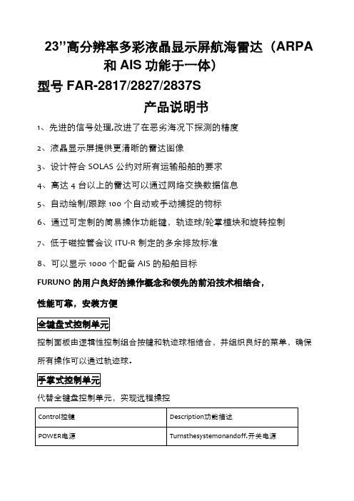
23’’高分辨率多彩液晶显示屏航海雷达
(ARPA和AIS功能于一体)
型号FAR-2817/2827/2837S
产品说明书
1、先进的信号处理,改进了在恶劣海况下探测的精度
2、液晶显示屏提供更清晰的雷达图像
3、设计符合SOLAS公约对所有运输船舶的要求
4、高达4台以上的雷达可以通过网络交换数据信息
5、自动绘制/跟踪100个自动或手动捕捉的物标
6、通过可定制的简易操作功能键,轨迹球/轮掌模块和旋转控制
7、低于磁控管会议ITU-R制定的多余排放标准
8、可以显示1000个配备AIS的船舶目标
FURUNO的用户良好的操作概念和领先的前沿技术相结合,
性能可靠,安装方便
控制面板由逻辑性控制组合按键和轨迹球相结合,并组织良好的菜单,确保所有操作可以通过轨迹球。
代替全键盘控制单元,实现远程操控
●IEC60936-1shipborneradar●IEC60936-2HSCradar
●IEC60872-1ARPA●IEC60872-2ATA
●IEC601993-2AIS●IEC60945Generalrequirements
●IEC61162-1ed2●IMOMSC.64(67)Annex4
●IMOA.823(19)●IMOMSC.74(69)Annex3
雷达可以连接到以太网网络,满足用户的各种要求。
SOLAS公约第五章修改规定了3000总吨及以上的船舶配备的X和S波段雷达可以互换
静态数据
船舶移动识别码IMO编码呼号和船名
船长与船宽船舶类型天线固定的船舶位置
航行相关数据船舶吃水危险货物类型目的港与预计抵达时间
动态数据
在世界时的精确船位对地航行对地航速船首向
航行状态(手动输入)转弯速率(可获得)速度和方向的更新率(2s–3min)
短的安全信息免费信息
警戒区
自动捕捉区
两个自动采集区可设置在一个量程或任何形式。
他们还可以作为抑制区,避免不必要的超载的处理器和杂波禁用自动捕获和跟踪的以外。
在一个自动采集区目标出现逆三角形。
操作者可以手动获得的重要目标无限制的。
CPA报警区域
目标跟踪符号变为三角形时,其预测过程(矢量)违反操作者设置的CPA/TCPA,操作者可以很容易地通过向量长度的改变来评估目标运动趋势。
警戒区和锚泊值班报警区域
保护区产生视觉和声音报警时目标进入警戒区。
一个保护区可作为一个锚泊位置,提醒值班人员本船或目标偏离设定区域的情况。
目标路径
目标轨迹特征产生单调或渐进的阴影,在屏幕上显示所有对象的余辉。
遮光余辉显示,就像一个模拟的PPI,唯一的创新是指自己的船舶运动和他船有用在一个特定的捕捞作业轨迹。
追踪时间可调15S,30S,1,3,6,15,30分钟或连续。
目标路径用背景不同的颜色表示。
该雷达独特的特征是可以选择真实的或相对模式相对运动(TM只有真正的)。
雷达地图
多达200个航路点,航线可以存储多达30条。
每个路径可以包含多达30个航路点。
雷达图结合图线和标志,用户可以定义和输入导航区,路径规划监测数据。
雷达图有3000点用于标识地图线和标志点。
地图数据可便于重复使用存储在常规导航地区。
夜景模式
Far-2817?/?2827/?2837s的规格
1、型号槽式波导阵列
2.波宽和旁波瓣衰减
S波段10英尺散热器用于HSC
3、转速
1.频率X-波段:9410MHz±30MHz,
S-波段:3050MHz±30MHz
2.输出功率FAR-2817:12kWRTR-078
FAR-2827:25KwRTR-079
FAR-2837S:30kWRTR-080
3.Pulselength/PRR脉冲选择
量程(nm)Pulselength(μs)PRR(Hz)
0.125,0.250.073000
0.50.07,0.153000
0.75,1.50.07,0.15,0.33000,1500
30.15,0.3,0.5,0.73000,1500,1000
60.3,0.5,0.7,1.21500,1000,600
12,240.5,0.7,1.21000,600
48,961.2600
1、显示屏
23.1'LCD(SXGA1280x1024pixels),470(H)x353(V)mm, 有效显示直径:340mm
回波颜色:黄色、绿色和白色32位
2、量程(海里)
0.125(.025),0.25(0.05),0.5(0.1),0.75(0.25),1(0.25)*,1.5(0.25),
圈间隔
2(0.5)*,3(0.5),4(1)*,6(1),8(2)*,12(2),16(4)*,24(4),32(8)*,48(8),96(16), 3、最小距离
30米×0.75海里尺度范围,在3.5米的高度使用一个10平方米的测试目标和在15米高的天线(IEC60936-1)。
不同条件下给一个不同的结果,可能接近20米的实际安装。
4、射程辨别
30米×0.75海里尺度范围
5、方位精度+0.2%
6、显示模式船首向上、船首向上TB(真方向)、真北向上、航向向上、真运动海浪或地面稳定。
7、船首向信息
FURUNO?GPS罗经sc-60?/?120是一个值得推荐的航向传感器,你船可作为一个罗盘备份。
8.平行刻度线可选择1、2、3或6条线
9、雷达地图
3、警戒区两个区域0.5海里的宽度
4、矢量真正的或相对的30,1,3,6,12,15,30分钟的预测目标运动
5、过去的位置5或10的位置,在过去的30S,1,2,3,6分钟内。
6、碰撞警报CPAlimit:0.2–10海里,,TCPAlimit:0-99分钟
7、试操纵动态或静态的,与选定的延迟时间
1、模式睡眠,激活,预警,选择中,失去目标
2、目标数量最大1000个目标
3、数据显示基本和扩展的数据
1.加工单元24VDC或115/230VAC,1?,50/60Hz
440VAC,1?,50/60Hz可选变压器RU-1803
2、显示单元24VDC或115/230VAC,1?,50/60Hz
440VAC,1?,50/60Hz可选变压器RU-1803
3、天线单元FAR-2837S:
230VAC,3?,60Hz;380VAC,3?,50Hz;440VAC,3?,60Hz
115VAC,3?,60HzwithoptionaltransformerRU-5693
230VAC,3?,50HzwithoptionaltransformerRU-6522
440VAC,3?,50HzwithoptionaltransformerRU-5466-1
1、显示单元mu-231cr
2、处理器rpu-013
3、全键盘控制单元rcu-014手掌式控制单元(Palm控制单元)rcu-015(订货时注明)
4、有线电视天线单元(15?/?20/?30/?50/?100米)
5、射频系统的射频收发单元
6、far-2837s电源单元psu-007
7、标准零件和安装材料
1、性能监视器pm-31为far-2817?/27pm-51为far-2837s(订货注明)
2、远程控制单元rcu-016
3、陀螺接口gc-10(内置处理器)
4、DVI模拟RGB转换盒(缓冲板内置)op-03-180
5、RGB连接器dsub-bnc-1(VDR)
6、卡接口单元cu-100
7、变压器ru-1803?/?5466-1?/5693?/6522
8、整流ru-3424?/?1746b9、接线盒rjb-00110、天线电缆rw-960011、外部报警蜂鸣器op03-2112、fp03-0984013、支架fp03-0982014、枢纽hub-100
航海者
显示单元可以提供一个特种柜相匹配的FURUNO新的插件,配置为
far-28x7系列。