赵凯华光学optics_19
南开大学光学工程内部课件Sep 7th
Brief history of optics (cont’ed)
平面镜 (《经下》19/—/42· —) 经:景迎日。说在转。 影子可以由反射(迎)太阳(的光线)形 成。理由在于翻转
经说:景,日之光反烛人,则景在日与人之间。
如果太阳之间
Brief history of optics (cont’ed)
母国光 战元龄著 《光学》 人民教育出版社
参考书目
ftp://202.113.227.137 Username: optics Password: optics-nk
/opt/index/
/course/optics/
《淮南万毕术》,公元前120左右,淮南王刘安及 其门客的著作。记录了用冰制作透镜的方法: “削冰令圆,举以向日,以艾承其影,则火生。” 还记录了潜望镜的雏形:“取大镜高悬,置水盆 于其下,则见四邻矣。”
Brief history of optics (cont’ed)
谭峭《化书》,约公元940年(南 唐)。书中有一段十分有趣的记 录:小人常有四镜。一名圭,一 名珠,一名砥,一名盂。圭视者 大,珠视者小,砥视者正,盂视 者倒。观彼之器,查我之型,由 是无大小,无短长,无妍丑,无 美恶。描述的很有可能是四种透 镜的成像性质。圭是双凹发散透 镜,珠是双凸透镜,砥是平凹透 镜,盂是平凸透镜。
一个受到光照射的人,看起来就好像他在发射出(光线)一样。人的下 部成为(像的)上部,而人的上部成为(像的)下部。人的脚(好像发 出)光在下方被遮蔽(即照到了针孔的下方),(但另一些光线)在上 方成像。人的头(好像发出)光在上方被遮蔽(即照到了针孔的上方), (但另一些光线)在下方成像。在(离开光源、反射体或像)较远或较 近的某个位置上,有一个距激光的点(端)(即针孔),结果像就只被 允许通过聚集之处(库)的光线所形成
2013年中国光学学会学术大会

大会顾问专家 ( 院士): ( 按姓氏笔画排序 )
干 福熹 方 家熊 牛 憨笨 王 育竹 王家骐 叶声华 刘 韵洁 许 祖 彦 邬 贺铨 苏 君红 周立伟 周寿桓 林祥 棣 林 尊琪 金 国藩 侯 洵 姚 建铨 姜 文汉 赵 伊君 赵梓森 高 伯龙 徐 至展 龚知本 龚 惠兴 黄维 彭垫墀 褚君 浩 简水生 学术委 员会 :
科研 院所 、军 工单 位 、企 事业 单位等 从事 光学 及光学 工程 领域 的专家 、科研 人 员、生 产人 员、硕 士生 、 博士生 及企 业管 理人 员和商 业人 士等 。 会 议将 出版论 文 摘要集 光盘 版 。提交 会议 的论文 将 由各分会 组织委 员会 审稿 ,并 根据论 文 质量 向中 国
光学学会指定的期刊推荐。
组 织机 构
大 会主 席 : 周炳琨 中国科学 院院士 ,中 国光 学学会 理事 长 ・
共主席 : 郭光灿 中国科学院院士,中国光学学会副理事长
曹 健林 国家科技 部副部 长 ,中 国光学学 会 常务理 事 杨 学军 中国科学 院院士 ,国防科 学技术 大学校 长 范滇元 中国工程 院院 士 ,湖 南大学 教授
周益春 湘 潭大 学学 院副 院长 夏 辉 中南大 学物理 与 电子学 院 系主任
( 下 转封三 )
2 0 1 3 年中国光学学会学术大会
\
会议主办单位:中国光学学会, 中国 科学院信息技术科学部,中国工程院信息与电子工程擎部
会议承办单位 :国防科技大学 会议协办单位 :湖南大学,中南大学,湘潭大学 ,长沙理工大学 ,湖南省光学学会 ,湖北省光学学会 会议时 间:2 0 1 3 年 8月 1 5日至 1 8日 会议地点 :湖南 长沙 国防科技大学 会议将 设立 约 1 9个专题 ,涵盖 光学 及光学 工程领 域近 1 0 0个子专 题研 究方 向 ;参会 人 员将 包括大 学 、
超快光学 啁啾函数 α β

超快光学啁啾函数α β
超快光学,作为光学领域中的一个重要分支,研究的是光的传输和控制速度的问题。
而啁啾函数则是在超快光学中常常使用的一种技术手段,它可以用来调控光信号的相位和幅度,实现对光信号的精确控制。
啁啾函数主要由两个参数α和β来描述,其中α代表了光信号的相位调制,而β则代表了光信号的幅度调制。
这两个参数的调节可以实现对光信号的快速调制和控制,从而实现光信号的高速传输和处理。
在超快光学中,啁啾函数被广泛应用于光通信、光存储、光计算等领域。
通过对光信号进行啁啾函数的调节,可以实现光信号的时域和频域的精确控制,从而提高光信号的传输速度和处理效率。
在光通信中,啁啾函数可以用来调节光信号的相位和幅度,实现光信号的快速调制和解调。
通过对光信号进行啁啾函数的调节,可以实现高速光信号的传输和处理,从而提高光通信系统的传输速度和容量。
在光存储中,啁啾函数可以用来调节光信号的相位和幅度,实现对光信号的精确控制和调制。
通过对光信号进行啁啾函数的调节,可以实现对光信号的快速存储和读取,从而提高光存储系统的存储速度和密度。
在光计算中,啁啾函数可以用来调节光信号的相位和幅度,实现对光信号的精确控制和调制。
通过对光信号进行啁啾函数的调节,可以实现对光信号的快速计算和处理,从而提高光计算系统的计算速度和效率。
啁啾函数作为超快光学中的一种重要技术手段,可以实现对光信号的精确控制和调制。
通过对光信号进行啁啾函数的调节,可以实现光信号的快速传输和处理,从而提高光通信、光存储和光计算等领域的性能和效率。
SNOM(理论与应用)
1
第2章
动力学方程的类比——模型引入的可行性
在量子隧穿的模型中,非相对论形式的动力学方程是著名的 Schrö dinger 方程
(
可变形为
2
2m
2 V ) E
( 2-1 )
(2
2m( E U )
2
) 0
( 2-2 )
此即
(2 k 2 ) 0
( 2-3 )
而对于作为电磁场的光场,又有 Helmholtz 方程
(2 k 2 ) E 0
( 2-4 )
由此,借用 STM 中的 s-波针尖模型,我们可以做如下图的模型
样品表面波函数为周期性的平面场 , 针尖的波函数由于其复杂性 , 我们将其简化 为半径为 R 的球形模型,其允许进入的波的模式为球波.成像信号为这两种模式的 光场的耦合,可以认为是能量在这两种模式的波场中的传递.
( 3-5 )
G 2 ( f x , f y )
( 3-6 )
3
为波矢的水平空间分量. 考虑到光场能量远小于样品的表面激发能量的情形,我们取
k/ / 0
( 3-7 )
为第一 Brillouin 区的原点, 则由如上代换可以直接得到光场的周期平面场的衰 逝部分
E( x, y, z ) E( f x , f y ,0)e
3.2
1s 球波与球形光场的衰逝部分
从众所周知的对量子力学中的球方势阱问题束缚态的求解中,给出在
ra
时,势阱外存在解
R( r ) Bk ' l
( 3-19 )
2k ' r
K
l
1 2
(k ' r )
( 3-20 )
物理光学简明教程PPT
由于当时牛顿在物理学界享有至高无尚的权威,人们普遍地 接受光的微粒说。
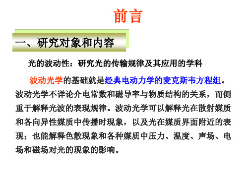
三、波动光学发展历史
到了19世纪前半叶,一连串的实验事实和根据波动说对 这些实验的成功解释,才使人们完全地抛弃微粒说,确
信光的波动说。 这些实验主要是:杨氏和菲涅耳等人的干涉实验、衍射
3.曲林杰等《物理光学》,北京:国防工业出版社,1980 4.叶玉堂 《光学教程》,北京:清华大学出版社
5.章志鸣等,《光学》, 北京: 高等教育出版社,2009 6.M.玻恩,E.沃耳夫《光学原理》(第七版), 杨葭荪译 北京:
电子工业出版社, 2009 7.A.加塔克,光学,梁铨廷等译,机械工业出版社,1984
中 国 光 学 薄 膜 在 线 中国光学光电子行业网
中国光学期刊网
国外 光学快报 /EJ(期刊中心) / / (MIT光物理实验室) /Optics/publications/ ( 英 国 University of Glasgow) http://mapageweb.umontreal.ca/hamamh/teach.htm ( 光 、 电信 号处理英文教程) /cm/new/viewleot.htm(激光,光电英文教程) /photonicslab/Resources/tutor ial/Alignment/alignment_tutorial.htm(在线教程) /index.html(在线教程) /library.html /(光子工业资源)
这种状态的改变一直延续到 19 世纪60年代,其时, 麦克斯韦在总结前人在电磁学方面的研究成果的基 础上,建立起一套完整的电磁场理论。他预言了电 磁波的存在,并指出光是一种波长很短的电磁波。
journal of optics
Home Search Collections Journals About Contact us My IOPscienceUltra-flattened chromatic dispersion control for circular photonic crystal fibersThis article has been downloaded from IOPscience. Please scroll down to see the full text article.2011 J. Opt. 13 055405(/2040-8986/13/5/055405)View the table of contents for this issue, or go to the journal homepage for moreDownload details:IP Address: 59.64.137.80The article was downloaded on 01/04/2011 at 02:19Please note that terms and conditions apply.IOP P UBLISHING J OURNAL OF O PTICS J.Opt.13(2011)055405(7pp)doi:10.1088/2040-8978/13/5/055405Ultra-flattened chromatic dispersion control for circular photonic crystalfibers Huizhen Xu1,2,Jian Wu1,Kun Xu1,Yitang Dai1,Cong Xu1andJintong Lin11Key Laboratory of Information Photonics and Optical Communications,Beijing Universityof Posts and Telecommunications,Ministry of Education,PO Box55(BUPT),Beijing100876,People’s Republic of China2College of Science,Jimei University,Xiamen361021,People’s Republic of ChinaE-mail:elimshee@(H Xu)Received5November2010,accepted for publication4March2011Published31March2011Online at /JOpt/13/055405AbstractA simple design procedure is utilized for achieving circular photonic crystalfibers withultra-flattened chromatic dispersion.This procedure only requires four parameters(threeair-hole diameters and one concentric spacing).The influence of the diameter of each air-holering on the circular PCF is investigated by simulations.The results show that the influence ofair-hole size of each ring on the dispersion weakens from the inside ring to the outside.Basedon the simulation results,an optimization procedure is utilized to control dispersion of thecircular PCF.Through the reasonable set of concentric spacing and air-hole diameters of theinner three rings,afive-ring circular PCF with aflattened dispersion of0±0.5ps km−1nm−1within the wavelength range of1.215–2.02μm is achieved.A low confinement loss of3.2×10−3dB km−1at1.55μm wavelength is simultaneously obtained.The influence ofmanufacturing imperfections of parameters on dispersion is also discussed to verify therobustness of our design.Keywords:chromatic dispersion,photonic crystalfiber(PCF),supercontinuum generation,ultra-flattened dispersion(Somefigures in this article are in colour only in the electronic version)1.IntroductionPhotonic crystalfibers(PCFs)are formed from a strand of silica glass with an array of microscopic air channels running along its length.Control of the dispersion of PCFs is of great importance for nonlinear applications,such as wide-band supercontinuum generation[1–3].Dispersion within the wavelength range of1–2μm is very important for supercontinuum generation with a1.55μm laser source because the output is mainly generated in this range.Both a small dispersion and a small dispersion slope within a broad wavelength range are desirable,so ultra-flattenedfiber dispersion is a crucial issue for PCFs.There are many previous reports on PCFs withflattened chromatic dispersion[4–8]. In order to obtain ultra-flattened chromatic dispersion,PCFs in some of these reports were engineered by simultaneously varying the air-hole diameters for all rings and hole-to-hole pitch.Reference[9]presented a hexagonal PCF with identical air holes,giving a dispersion of0±0.6ps km−1nm−1from 1.24to1.44μm.However,up to455holes were needed to decrease the confinement loss of the PCF,which causes complexity in the manufacturing process.In[10],the pitch and the air-filling fraction of all holes were changed for a wideflattened dispersion wavelength range.A PCF with a dispersion within0±0.5ps km−1nm−1from about1.3to 1.7μm wasfinally obtained.It was pointed out in this paper that achieving ultra-flattened dispersion over such a large wavelength range involves very accurate control of the air-hole diameter and the pitch.In[6],the authors presented an eight-ring octagonal PCF.After optimization of the diameters of the first ring,the outer seven rings and the air-hole pitch between rings,a design with a dispersion of0±0.5ps km−1nm−1 in a wavelength range of1.46–1.66μm was obtained.The confinement losses are less than0.06dB km−1.However,theoctagonal structure increases the difficulty during the process of scheduling preforms.Moreover,it contains eight air-hole rings in the cladding.So far,there are no real octagonal PCFs reported to our knowledge.In[11],a novel design with four or five rings of gradually increasing air-hole diameters for each ring was proposed for achieving ultra-flattened dispersion. Through optimization,a four-ring PCF with a dispersion of 0±0.5ps km−1nm−1from a wavelength of1.19–1.69μm and afive-ring PCF with a dispersion of0±0.4ps km−1nm−1from a wavelength of1.23–1.72μm were proposed.These designs significantly reduce the ring number of air holes,but it needs several parameters:five(four air-hole diameters and one pitch) for the four-ring PCF and six(five air-hole diameters and one pitch)for thefive-ring one.The more parameters,the harder it is for manufacturing.The confinement losses were less than 1dB km−1for thefive-ring PCF from1.1to1.8μm.In this paper,a simple optimization procedure is utilized for the circular PCF(C-PCF)dispersion control.The numbers of optimization parameters are reduced to four.Only one concentric spacing and three air-hole diameters need to be considered during the optimization.It was pointed out in[11] that more than20rings of air holes are required in the cladding region to reduce the confinement loss to a level of 0.1dB km−1.In our design,a dispersion wavelength range of0±0.5ps km−1nm−1from1.225to1.84μm for a four-ring C-PCF and from1.215to2.02μm for afive-ring C-PCF are obtained.Low fundamental mode confinement loss of3.2×10−3dB km−1for thefive-ring PCF is obtained.In[12],a hexagonal and circular hybrid structure based on pure silica was fabricated.It also needed to control four parameters during the manufacturing.So,our circular structure may be realized. Moreover,nowadays there are several ways of assembling a PCF,and one of them consists in using rods and capillary tubes which are not necessarily circular,but rather made six-or eight-sided.This helps quite a lot in stacking them together. Things like that may help obtain this circular hole arrangement.2.Design principle and the resultsThe structure of the C-PCF with uniform air holes is shown in figure1.The spatial positions of the air holes on the x–y plane are[13]x=RN cos2nπ6N,y=RN sin2nπ6N,n=1∼6N(1)where R and N denote the concentric spacing and number of rings,while d n(n=1–5)is the air-hole diameter of the N th air-hole ring.This design has a circular photonic crystal structure and isfirst proposed for micro-cavity lasers[14–16]. In this paper,we use this structure for a PCF design with ultra-flattened dispersion.The BeamPROP module of the commercial software package Rsoft(RSoft Design Group,Ossining,NY)is used for the simulations.During our simulations,the transparent boundary condition(TBC)[17]is used for calculating the real part of the fundamental mode index n eff and thetolerance Figure1.Cross section of the circular PCF withfive rings of identical air holes.for convergence is as low as1×10−7.The simulations are performed in a window of25μm×25μm within the transverse x–y plane of the PCF,in steps of z=0.1μm, x= y= 0.02μm.The asymmetry in the x and y directions which can be seen from the cross section will lead to birefringence. However,through simulations it is found that the differences between the TE mode index and TM mode index(with the same geometrical parameters)are very small(of the magnitude of10−6).Therefore,there is no need to take birefringence into consideration.The refractive index of the fused silica is given by the Sellmeier dispersion equationn2m(λ)=1+3i=1A iλ2λ2−λ2i.(2)We take the values of coefficients A i andλi from[18].After the modal effect,the effective mode index n eff is obtained.The mode dispersion D and the effective mode area A eff could be easily calculated.The chromatic dispersion D[11]is defined asD=−λcd2Re(n eff)dλ2(3)where c is the velocity of light in vacuum and Re stands for the real part of the fundamental mode n eff.The effective mode area A eff and the nonlinear parameterγare calculated byA eff=(|E|2d x d y)2|E|4d x d y(4)γ=2πn2λA eff(5) where n2=2.6×10⁻²⁰m2W−1is the nonlinear index for fused silica[19].The confinement loss L c is calculated from the imaginary part of the fundamental mode index using the following equation[20]:L c(d B/m)=20ln(10)2πλIm[n eff]×106(6)Figure2.The influence of f1–f5on the dispersion,where(a)R=1.5μm,f2=f3=f4=f5=0.9,(b)R=1.5μm,f1=0.4,f3=f4=f5=0.9,(c)R=1.5μm,f1=0.4,f2=0.7,f4=f5=0.9,(d)R=1.5μm,f1=0.4,f2=0.7,f3=0.8,f5=0.9and (e)R=1.5μm,f1=0.4,f2=0.7,f3=0.8,f4=0.9.whereλis given in micrometers.The perfectly matched layer (PML)boundary condition is selected for the imaginary part of the mode index calculation.2.1.Influence of air-hole diameters of each ringIt is known that,in order to achieveflat dispersion with an identical air-hole size structure,the air-filling fraction has to be small.Therefore,it requires a large quantity of air holes to get better confinement.Moreover,it is hard to obtain a very wideflat dispersion wavelength range.In order to obtain an ultra-flattened dispersion without increasing the cladding air-hole rings and also with good confinement,the influence of the air-hole diameter of each ring on the dispersion profile is investigated.We define a local air-filling fraction f n=d n/R.Then f1–f5are varied from0.1to0.9with an increment of0.1to investigate their influence on the dispersion.The local air-filling fractions are gradually varied from the inner ring to the outer,andfigure2shows their influence on the dispersion.It is clear infigure2that the air-hole size of thefirst ring has the greatest influence on the dispersion and the dispersion slope.The influence of the air-hole size on the dispersion curve decreases from the inside ring to the outside.That can be explained by the coupling effect between the core mode and the cladding mode.When we investigate thefirst air-hole ring, the outer four rings(from the second tofifth ring)are viewed as cladding.The variation of thefirst air-hole size will affect the coupling between the core mode and the cladding mode and introduce a mode transition,thereby affecting the dispersion curve.Thefirst air-hole ring can be viewed essentially as a slot layer in a slot waveguide[21].The core mode is partlyconfined in the core by thefirst air holes.Therefore,thevariation of the second air-hole size has a smaller influence onthe mode transition between the code mode and the claddingmode.That is to say,the second ring has a smaller influenceon the dispersion curve than thefirst ring.The influence on thedispersion curve is becoming smaller from the inside ring tothe outside.This provides additional design freedom to tailorchromatic dispersion.Infigure2(a),when f1is below0.5,the curve slopes are positive.In the longer wavelength range,the dispersion valuedecreases and becomesflat with the increase of f1.However,when f1is larger than0.5,the slopes change from positive to negative as the wavelength increases.The contributions of air-hole size to the overall dispersion vary with wavelength alsodue to the mode transition.The core mode area increaseswith the increase of the wavelength and spreads to the air-hole cladding which has a lower refractive index.This willlead to the reduction of the core mode and then changes thedispersion curve.Infigure2(b),the influence of f2is shown. Obviously,f2has a smaller influence on the dispersion andthe dispersion slope.It is shown that,when f2is larger than0.5,the curves becomeflat.In addition,the dispersionvalue increases as f2increases,while the curve shape does not undergo a large change.It can be found fromfigure2(c)that f3has almost no influence on the dispersion profile inthe shorter wavelength range.It only affects the curves aboveabout1.2μm.As we all know,the coupler coefficient is in connection with wavelength.The coupling within a longerwavelength range is stronger than within the shorter one.Inthe case of larger f2,the variation of f3can hardly affect the coupling between the core mode and the cladding mode withina shorter wavelength,while the influence will be enhancedwith the increase of wavelength.The dispersion increases inthe medium and longer wavelength range when f3increases.Figure2(d)shows that f4has very little influence on the dispersion profile.When f4varies,the dispersion curve has a slight change in the longer wavelength range and almost nochange within shorter and medium wavelength ranges.Fromthe influence of f5shown infigure2(e),it is found that all of the curves coincide with each other.We can conclude that f5 has no influence on the dispersion in the case that f4is large enough and approximately equal to1.2.2.Design procedureBased on the above simulation results,a simple design processis utilized to control dispersion of a C-PCF.It was pointed outin section2.1that the inner three rings have a larger influenceon the dispersion,while the fourth andfifth rings have littleinfluence.However,large values of f4and f5give better confinement of PCF[22,23].Therefore,we set f4=f5=0.9 during the following simulations.Based on the results showninfigure2,the design process is as follows:Step1.Choose f1=0.4and scan f2from0.71to0.79. That is becausefigure2(a)indicates the curve of f1=0.4 isflatter than the other curves andfigure2(b)shows that the dispersion values of the two curves(f2=0.7and0.8)are close to zero.The results are shown infigure3(a).Thecurves Figure3.Design procedure,where(a)R=1.5μm,f1=0.4,f3=f4=f5=0.9,(b)R=1.5μm,f1=0.4,f2=0.73,f4=f5=0.9,and(c)f1=0.4,f2=0.73,f2=0.37,f4=f5=0.9of f2=0.76–0.79are not shown infigure3(a)because their dispersion values are far from zero.Step2.Simulation results shown infigure3(a)indicate that, in order to obtain aflattened dispersion,we have to decrease the dispersion value in the longer wavelength range.From figure2(c),we know that the dispersion decreases as f3 decreases in the medium and longer wavelength ranges.Based on these results,we choose f2=0.73and scan f3from0.3to 0.4with an increment of0.05.It is shown that the dispersion values of the curve f3=0.35is below zero.However,when f3changes from0.35to0.4,the dispersion values in the longer wavelength range become larger than zero.So we then scan f3 from0.36to0.39to obtain a near-zero dispersion andflatter dispersion curve.The scan results are shown infigure3(b). Step3.In order to make the dispersion value closer to zero, R is varied from1.51to1.55μm.Figure3(c)shows that the dispersion curve changes as a whole when R varies.ThroughTable1.Parameters of the four-ring andfive-ring circular PCFs with ultra-flattened dispersion.Geometric parameter Wavelength rangewith a dispersion of0±0.5ps km−1nm−1Dispersion valueat1.55μm(ps nm−1km−1)Dispersion slopeat1.55μm(ps nm−2km−1)Nonlinear parameterat1.55μm(W−1km−1)Confinementloss at1.55μm(dB km−1)Four-ring PCF1#R=1.54μm,f1=0.39,f2=0.71,f3=0.35,f4=0.91.225–1.84μm−0.027−1.905×10−513.812.3Five-ring PCF2#R=1.47μm,f1=0.4,f2=0.76,f3=0.34,f4=f5=0.91.215–2.02μm−0.247−1.162×10−515.73.2×10−3the variation of R,it is possible to move the dispersion curve to near zero.Step4.Finally,control the dispersion curve to meet our demand throughfine-tuning the four parameters.Through the above steps,we obtain aflat dispersion curve.The inner three air-hole sizes are used for dispersion control,while the other outer rings are for better confinement. Figure4shows the four-ring andfive-ring designs obtained based on the above procedure.Figure4(a)shows dispersion profiles of the four-ring PCF1#and thefive-ring PCF2#, andfigure4(b)shows the confinement loss and nonlinear parameters of the four-ring PCF1#and(c)thefive-ring PCF 2#,respectively.It is found that the confinement losses of the four-ring PCF increase quickly when the wavelength is larger than1.7μm due to the small diameter of the third ring air holes.Thefive-ring PCF overcomes this shortcoming and greatly enhances the confinement loss.The geometric parameters,flat dispersion wavelength range,dispersion value, dispersion slope,nonlinear parameters and confinement losses at1.55μm wavelength of these two PCFs are listed in table1.Reference[11]proposed a four-ring PCF withflattened dispersion of0±0.5ps km−1nm−1from a wavelength of1.19 to1.69μm and with confinement losses less than10dB km−1. Compared to our four-ring circular PCF,the wavelength range of dispersion within0±0.5ps km−1nm−1is from1.225to 1.84μm,up to615nm.Reference[6]proposed an eight-ring octagonal PCF with a dispersion of0±0.5ps km−1nm−1 from1.46to1.66μm and with confinement losses less than 0.06dB km−1,while ourfive-ring PCF with a dispersion of 0±0.5ps km−1nm−1is from1.215to2.02μm,up to805nm wavelength range.The confinement loss at1.55μm is3.2×10−3dB km−1.Figure5shows the transverse fundamental mode profiles of the PCF1#and the PCF2#at1.55μm wavelength.The energy is well confined to the inner two rings, and most of the energy is in the silica core.3.Manufacturing toleranceBecause of the small size of the air holes in the PCFs,one important issue to be considered during the manufacturing process is the dispersion tolerance to imperfect manufacture. Furthermore,the inevitable parameterfluctuations induced during the manufacturing process complicate the validityof Figure4.(a)Dispersion curves of four-ring PCF1#andfive-ring PCF2#,nonlinear parameters and confinement loss of(b)four-ring PCF1#and(c)five-ring PCF2#.predictions based on perfectfibers[24].It is known that the parameters can only be guaranteed with limited precision[25]. Therefore,a robust estimation is conducted for our design. The values of air-hole diameters as well as the concentric spacing are varied in±1%,±2%and±5%from their optimum value.Note that a variation of overall parameters serves to provide an upper bound on the severity of the manufacturingFigure 5.The transverse fundamental mode profile of (a)PCF 1#and (b)PCF 2#at 1.55μmwavelength.Figure 6.The dispersion behavior of the five-ring ultra-flattened PCF with variation of ±1%,±2%and ±5%for all parameters,simultaneously.imperfections,because in reality not all the holes are distorted from their optimum value in the same way,and some averaging effect is likely to occur [23,25].However,these two papers also point out that non-symmetric hole changes will break the symmetry of the fiber and introduce polarization mode dispersion.These consequences of manufacturing errors are not captured in this paper.We just change all hole sizes but maintain the fiber symmetry to investigate the manufacturing tolerance.Figure 6shows that the ultra-flattened dispersion behavior does not change significantly with a fluctuation of ±1%,±2%and ±5%for all optimized parameters.The fluctuation of parameters changes the dispersion values,but the whole curve remains flat throughout the communications wavelength range even if all the parameters have a ±5%variation.The ultra-flattened dispersion PCF that we propose is robust to fabrication imperfections.4.ConclusionIn this paper,the influence of the local air-filling fractions on the dispersion profile of a C-PCF has been investigated.f 1has the greatest influence on the dispersion profile within the 1–2μm wavelength range.As long as f 1varies,the dispersion curve and the dispersion slope changes significantly.f 2has a smaller influence on the dispersion,followed by f 3.Althoughf 4and f 5have almost no influence on the dispersion profile,they play an important role in the confinement loss of the PCF.According to our simulation results,ultra-flattened dispersion can be achieved through the adjustment of air-hole diameters of the inner three rings and concentric spacing,while the other outside air-hole rings are adjusted for better confinement.This optimization process needs only four parameters.From the simulation results,a four-ring PCF and a five-ring PCF with a dispersion of 0±0.5ps nm −1km −1from 1.225to 1.84μm and from 1.215to 2.02μm are demonstrated.A low confinement loss of 3.2×10⁻³dB km −1for the five-ring PCF at 1.55μm wavelength is simultaneously achieved.These PCFs with ultra-flattened dispersion and low confinement loss will be useful for supercontinuum generation.AcknowledgmentsThis work was partly supported by the 863program 2009AA01Z256,2009AA01Z253and 2008AA01A331,NSFC program 60736036,60702006,60837004,60736002and 60932004and MOST program 2008DFA11670.References[1]Kudlinski A,Bouwmans G,Douay M,Taki M andMussot A 2009Dispersion-engineered photonic crystalfibers for CW-pumped supercontinuum sources J.Lightwave Technol.271556–64[2]Roy A,Leproux P,Roy P,Auguste J-L and Couderc V 2007Supercontinuum generation in a nonlinear Yb-doped,double-clad,microstructured fiber J.Opt.Soc.Am.B 24788–91[3]Hilligsøe K M,Andersen T V,Paulsen H N,Nielsen C K andMølmer K 2004Supercontinuum generation in a photonic crystal fiber with two zero dispersion wavelengths Opt.Express 121045–54[4]Ferrando A,Silvestre E and Andres P 2001Designing theproperties of dispersion-flattened photonic crystal fiber Opt.Express 9687–97[5]Renversez G and Kuhlmey B 2003Dispersion managementwith microstructured optical fibers:ultraflattened chromatic dispersion with low losses Opt.Lett.28989–91[6]Abdur Razzak S M and Namihira Y 2008Proposal for highlynonlinear dispersion-flattened octagonal photonic crystal fibers Photon.Technol.Lett.20249–51[7]Ghosh D,Roy S,Pal M,Bandyopadhyay S and Bhadra S2009Modeling of microstructured nonzero dispersion shiftedopticalfiber with ultralow dispersion slope J.Opt.Soc.Am.B26337–45[8]Chaudhari C,Suzuki T and Ohishi Y2009Chalcogenide corephotonic crystalfibers for zero chromatic dispersion in theC-Band Optical Fiber Communication Conf.(OFC)PaperOTuC4[9]Reeves W H,Knight J C and St Russell P J2002Demonstration of ultra-flattened dispersion in photoniccrystalfibers Opt.Express10609–13[10]Ferrando A,Silvestre E,Miret J J and Andres P2000Nearlyzero ultraflattened dispersion in photonic crystalfibers Opt.Lett.25790–2[11]Saitoh K and Koshiba M2003Chromatic dispersion control inphotonic crystalfibers:application to ultra-flatteneddispersion Opt.Express11843–52[12]M´e lin G,Provost L,Fleureau A,Lempereur S,Rejeaunier X,Bourova E and Gasca L2004Innovative design for highlynon-linear microstructuredfibers ECOC:30th EuropeanConf.on Optical Communication p415-0084-1[13]Lee P-T,Lu T-W,Fan J-H and Tsai F-M2007High qualityfactor microcavity lasers realized by circular photoniccrystal with isotropic photonic band gap effect Appl.Phys.Lett.90151125[14]Scheuer J and Yariv A2004Circular photonic crystalresonators Phys.Rev.E70036603[15]Chaloupka J,Zarbakhsh J and Hingerl K2005Local density ofstates and modes of circular photonic crystal cavities Phys.Rev.B72085122[16]Chang D,Scheuer J and Yariv A2005Optimization of circularphotonic crystal cavities-beyond coupled mode theory Opt.Express139272–9[17]Hadley G R1991Transparent boundary condition for the beampropagation method Opt.Lett.16624[18]Malitson I H1965Interspecimen comparison of the refractiveindex of fused silica J.Opt.Soc.Am.551205–8[19]Agrawal G2001Nonlinear Fiber Optics3rd edn(New York:Academic)[20]Kuhlmey B,Renversez G and Maystre D2003Chromaticdispersion and losses of microstructured opticalfibers Appl.Opt.42634–9[21]Zhang L,Yue Y,Beausoleil R G and Willner A E2010Flattened dispersion in silicon slot waveguides Opt.Express1820529–34[22]Abdur Razzak S M and Namihira Y2008Tailoring dispersionand confinement losses of photonic crystalfibers usinghybrid cladding J.Lightwave Technol.261909–14[23]Nguyen H H,Namihira Y,Kaijage S,Begum F,Kinjo T andRazzak S M A2007An unique design of ultra-flatteneddispersion photonic crystalfibers SBMO/IEEE MTT-S Int.Microwave and Optoelectronics Conf.pp46–9[24]Cucinotta A,Selleri S,Vincetti L and Zoboli M2002Perturbation analysis of dispersion properties in photoniccrystalfibers through thefinite element method J.LightwaveTechnol.201433–41[25]Reichenbach K and Xu C2005The effects of randomlyoccurring nonuniformities on propagation in photonic crystalfibers Opt.Express132799–807。
飞秒激光双光子聚合方法加工图案化微透镜及其成像测试
第28卷第12期2020年12月光学精密工程Optics and Precision EngineeringVol.28No.12Dec.2020文章编号1004-924X(2020)12-2629-07飞秒激光双光子聚合方法加工图案化微透镜及其成像测试苏亚辉1>2'3*,秦天天】,许兵4,吴东4(1.安徽大学电气工程与自动化学院,安徽合肥230601;2.安徽大学电子信息工程学院,安徽合肥230601;3.信息材料与智能感知安徽省实验室,安徽合肥230601;4.中国科学技术大学精密机械与精密仪器系,安徽合肥230022)摘要:为改善以往图案化透镜加工工艺复杂、制造技术昂贵、图案设计方面有限制等缺点,本文将飞秒激光双光子聚合加工技术应用于图案化微透镜的快速、高精度加工。
通过球面波因子的变形设计了不同图案的微透镜,利用飞秒激光双光子聚合加工技术在光刻胶样品中加工出图案化的微透镜,然后将光刻胶样品置于显影液中去除未聚合部分,得到图案化微透镜,最后对图案化微透镜进行成像测试和光强均一化分析。
将LED光源分别置于不同图案微透镜的下方,光线透过图案化微透镜成功聚焦出光强一致的焦点图案。
实验结果表明,使用飞秒激光双光子聚合加工可以实现灵活可控的3D图案化微透镜结构的加工,采用加工功率为7mW,曝光时间为2ms,扫描xy步距为0.5pm,步距为0.8〜1.5卩m,不仅保证了微透镜结构表面光滑,而且实现了微透镜的快速加工。
该技术在加工光学超材料、光学微器件、集成光学器件等方面具有广阔的应用前景。
关键词:激光加工;飞秒激光;双光子聚合;微透镜;光刻胶中图分类号:TN249文献标识码:A doi:10.37188/OPE.20202812.2629Patterned microlens processed using two-photon polymerization of femtosecond laser and its imaging testSU Ya-hui1,2,3*,QIN Tian-tian1,XU Bing4,WU Dong4(1.School of E lectrical Engineering a^id Automation,Anhui Uni r v ersity,Hefei230601,China;2.School of E lectronic Information Engineering,Anhui University,Hefei230601,China;3.AnhuiProvincialLaboratory of InformationMaterialsandlntelligentPerception,Hefei230601,China;4.Department of P recision Machinery and Precision Instrumientation,University of Science and Technology of China,Hefei230022,China)*Corresponding author,E-mail:u stcsyh@Abstract:Two-photon polymerization technology for use in a femtosecond laser was used in the rapid and high-precision processing of a patterned microlens to improve the previous shortcomings,including a com-收稿日期:2020-09-01;修订日期:2020-09-28.基金项目:安徽省高等教育学校自然科学基金重点项目(No.KJ2018A014);中国博士后科学基金会资助项目(No.2019M662190);中央高校基础研究经费资助项目(No.WK2090000016)2630光学精密工程第28卷plex processing technology,expensive manufacturing technology,and limited pattern design.First,threedimensional software was used to design the microlens pattern through the deformation of the spherical wave factor,and the two-photon polymerization processing technology for a femtosecond laser was used to process the patterned microlens in the photoresist sample.The sample was then placed in a developer to remove the unprocessed area and obtain the corresponding patterned microlens.Finally,an imaging test and a light intensity homogenization analysis of the patterned microlens were carried out.An LED light source was placed below the patterned microlens,and the light was successfully focused through the patterned microlens to obtain the corresponding patterns with the same light intensity.The experiment shows that the two-photon polymerization of a femtosecond laser can realize the flexible and controllable processing of a 3D microlens structure,a processing power of7mW,an exposure time of2ms,a scanning xy-step of0.5 pm,and a z-step of 0.8-1.5pm,ensuring the smooth surface of the microlens structure and realizing a rapid microlens processing.The two-photon polymerization technology for a femtosecond laser will play an important role in the processing field such as optical metamaterials,optical microdevices,and integrated optical devices.Key words:laser fabrication;femtosecond laser;two-photon polymerization;microlens;photoresist1引言光学器件的小型化、集成化是现代光学系统发展的重要趋势[11o近几十年来,作为一种重要的微光学器件,微透镜由于其体积小、质量轻、光学性能优异等优点在微成像[21、光束整形[31、人工复眼[41等方面的应用十分广泛。