Kistler-Morse SVS 2000快速服务手册
WES-2000B型 电液数显万能材料试验机 使用说明书 1.主要概述 WES ...

WES-2000B型电液数显万能材料试验机使用说明书1.主要概述WES系列电液数显万能材料试验机采用电液数显和手动液压加载、主体与控制柜分置的设计,具有操作方便、工作稳定可靠、试验精度高、加力平稳的特点,也适用于金属、水泥、混凝土、塑料等材料的拉伸、压缩、弯曲、剪切试验。
建议在满足下列条件的环境中安装和使用本设备:a.清洁、干燥、无震动,周围有供试验和维护用的空间(≥0.7m);b.室温为10℃-35℃。
产品规格和主要技术指标见附表。
2.主机结构原理2.1机械结构原理本设备主体部分由高度可调的支撑架[由机座、丝杆及移动横梁(下钳口座)组成]和工作框架[由工作油缸、活塞、台板、支架及上横梁(上钳口座)组成]。
其工作原理为:由高压油泵向工作油缸供油,通过活塞运动,推动台板和上横梁(上钳口座)向上运动,进行试样的拉伸或压缩试验。
拉伸试验在主机的上横梁与移动横梁之间进行,压缩试验在主机的台板与移动横梁之间进行。
试验空间的调整通过驱动机构(升降电机、链轮、链条等)驱动双丝杆同步旋转使移动横梁升降达到。
2.2电气原理本设备采用三相四线、50Hz交流供电。
主回路包括油泵电机和升降电机,在主回路和控制回路中分别接有熔断器以防止过大的电流,在油泵电机和升降电机前还串联了热继电器以防止电机过载。
3.安装3.1开箱验收当您开箱后,请根据定货合同和装箱单对设备及附件的数量进行核对并检查是否完整,如发现短缺或损坏请尽快通知本公司以便及时处理。
3.2安装前准备试验机应安装在清洁、干燥、无震动而且室温为10℃-35℃的房间内,在试验机的周围应留出足够的空间(≥0.7m)供试验和维护用。
试验机的主体及控制柜应安装在混凝土基础上。
基础尺寸根据外形及地基图规定,留出地脚螺钉及其它电线安装管道等装置,基础的上平面应用水平仪找正。
3.3试验机安装精度的初步校正主体初步校正:使用框式水平仪或借用附件中的线锤在相互垂直的两个方向校正立柱的垂直度,用在主体底部插入小斜铁的方法调整。
CVIPC2000 manual 马头 工具 软件 手册

6159932082-05English1 / 38CP Georges Renault - ZAC de la Lorie - 38 Rue Bobby SandsBP 10273 - 44818 Saint-Herblain Cedex - France©© Copyright 2009,All rights reserved. Any unauthorized use or copying of the contents or part thereof is prohibited. This applies in particular to trademarks, model denominations, part numbers and drawings. Use only authorized parts. Any damage or malfunction caused by the use of unauthorised parts is not covered by Warranty or Product Liability.CVIPC2000 Release 3.8.1 and higherOperator’s manual N° 6159932082-056159932082-05English2 / 38Warning.With a view to constantly improving its products, Desoutter reserves the right to introduce all the changes as it may deem necessary to the products described herein, without prior notice.This document contains a section in French language (original version) and sections in foreign languages which correspond to its translation. Should any dispute arise, the French section shall be deemed authentic.This document includes important notes relating to safety. These are mentioned as follows:This document also includes essential instructions to use the product, as well as general information. These are mentioned as follows:Safety noteEssential instructionGeneral information6159932082-05English3 / 38TABLE OF CONTENTSWarning (2)1 - INTRODUCTION (5)1.1 - Transfer mode and Command mode (5)1.2 - Point-to-point connection and multipoint connection (5)1.3 - Installation (5)1.3.1 - Hardware and software requirements (5)1.3.2 - CVIPC software protection (5)1.3.3 - Installation (6)1.3.4 - Upgrading the controller software (6)1.3.5 - Upgrading the CVIPC software (6)1.3.6 - Uninstalling (6)1.4 - Initiating the Program (7)2 - CREATING A STATION (8)2.1 - Creation (8)2.2 - Copying a station (11)2.3 - Deleting a Station (11)3 - PARAMETERS (12)3.1 - Controller (12)3.1.1 - Serial ports RSA and RSB (12)3.1.2 - Ethernet Link (13)3.1.3 - Peripherals (13)3.2 - Notepad (15)3.3 - Spindles (15)3.4 - Cycles (16)3.4.1 - Add a cycle (18)3.4.2 - Add a phase (18)3.4.3 - Delete (18)3.4.4 - Copy (18)3.4.5 - Paste (18)3.4.6 - Cycle parameters (18)3.4.7 - Phase parameters (18)3.4.8 - Phase Type (18)3.4.9 - Instructions (19)3.4.9.1 - Search Sequence Phase (19)3.4.9.2 - Run Down Speed Phase (19)3.4.9.3 - Final Speed Phase (20)3.4.9.4 - Run Reverse Phase (21)3.4.9.5 - Action on NOK phase (21)3.4.9.6 - Prevailing torque phase (22)3.4.9.7 - Synchro waiting phase (not available on CVIS) (22)3.4.9.8 - Jump phase (23)3.4.9.9 - Angle rundown phase (for CVIC only) (23)3.4.9.10 - List of spindles (23)3.5 - Curves (23)4 - RESULTS (24)4.1 - Tightening (24)4.1.1 - Display (24)4.1.2 - Printing (24)4.1.2.1 - Detailed report codes in PC4 format (25)4.1.2.2 - Detailed binary report codes in 32 bits (0 or 1) (26)4.1.3 - Specific format (26)4.1.4 - Archiving and erasing (27)4.2 - Curves (curve display) (27)4.3 - Statistics (28)4.3.1 - General (28)4.3.2 - Values (28)6159932082-05English4 / 384.3.3 - Statistics (29)5 - MAINTENANCE (30)6 - DATA TRANSFER (31)6.1 - PC --> Station (31)6.2 - Station --> PC (31)6.3 - Station - PC comparison (31)6.4 - CVINet Data Collector (31)6.5 - ToolsNet Data Collector (31)6.6 - Automatic transfer of results (31)6.7 - Grafcet (31)6.8 - Channel test (31)7 - PRINTING (32)7.1 - Station Parameters (32)7.2 - List of Stations (32)8 - SERVICES (33)8.1 - Access Code (33)8.2 - Registration Code (33)8.3 - PC Communications (33)8.4 - Automatic uploading / Backup (34)8.5 - General parameters (35)8.6 - PC Language (35)8.7 - Printer Setup (35)8.8 - Number of curves (35)8.9 - File Management (35)8.10 - Manage privileges (35)8.11 - Manage your login (35)9 - COMMAND MODE (36)9.1 - Control window (36)9.2 - Test window (37)Spindle start (38)Cycle (38)Sensitivity (38)Inputs/Outputs (38)6159932082-05English 5 / 38INTRODUCTION1 - INTRODUCTION This manual explains how to use the CVI range software: CVIPC 2000.The CVIPC software can be used with all the control systems of the CVI series (TWINCVI, MODCVI, CVIS, MULTICVI, CVIC and MULTICVIC controllers).It offers a complement to the use of the controller(s) and allows the user to:•program the cycles and then upload them to the controllers•process the tightening results in the form of curves and statistical calculations•increase the memory capacity to save the results and curves•save the parameters and results•transfer data to a spreadsheet for subsequent analysisThe additional advantage offered by the Advanced CVIPC 2000 software is that it can control up to 16 networked controllers in real time (in command mode).The software can be equally operated in Windows XP or Windows Vista.1.1 - Transfer mode and Command modeThe software can operate in two modes: the Transfer mode and the Command mode.The first mode allows the operator to upload the parameters from the PC to the controller or to download data from the controller to the PC while the second mode is used to monitor the controller in real time.1.2 - Point-to-point connection and multipoint connectionTwo types of connection are available between the PC and the controller:•the point-to-point connection is a connection between the PC and a single controller•the multipoint connection allows the user to connect several controllers at the same time.Each mode (Transfer/Command) can be used with each type of connection. The standard use is the point-to-point connection.The multipoint connection requires a specific configuration of the addresses of the controllers (the network address should be specific of each controller).The CVI can be connected to the PC via an Ethernet gateway or an integrated Ethernet link (TWINCVI). In that case, each station has a network address which must correspond to the IP address of the CVI. See section 3 - “PARAMETERS”.1.3 - Installation1.3.1 - Hardware and software requirementsThe computer should be of PC type and have at least one serial port or an Ethernet connection.1.3.2 - CVIPC software protectionThe software is protected by a registering code. As long as this code has not been entered, the software is run in Demo mode This software version is limited to 90 days' operation.By or before the end of the 90-day evaluation period, you must request your registering code to be allowed to continue using the software.To do so, a standardised registering form is available. This form is available when starting the program or by clicking on the See Info button or through the Services / Registering code menu. Copy the form into an email, complete it and send it to Desoutter atthe address: tightening.support@.The link is of the following type:RS232 for a point- to-point link between the PC and a controllerRS422 for a network of several controllers.The standard CVIPC software is used for the point-to-point connection of a single controller.The CVIS/CVICPC software is used for the point-to-point connection of a single CVIS/ CVIC controller.The Advanced CVIPC software is used for the multipoint connection of 16 controllers.Each time the software is run, a message that indicates the number of remaining days before the evaluation is dis-played. When the period has elapsed, a warning message is displayed: "You are not allowed to run this software!".To know which software type and version is installed, click on menu ? / About... .6159932082-05English6 / 38INTRODUCTION1.3.3 - InstallationUse the CD to install the software. Open the Install file, then Disk1and double-click on Setup.exe.Select the path for installing the software (by default C:\Georges Renault\CVIPC 2000) and follow the instructions on the screen.1.3.4 - Upgrading the controller softwareUpgrading the controller software will involve a loss of previously saved data (cycle parameters, tightening results). To avoid this, it is recommended to download all data from the controller to the PC before upgrading.1.3.5 - Upgrading the CVIPC softwareThe upgrading software allows you to upgrade the CVIPC (licensed) software. Please contact our departments.1.3.6 - UninstallingIt is very important to take note of your uninstalling code to be able to reinstall the software on another PC. This uninstalling code MUST be provided to the technical assistance department with the public key to obtain a new private key for installing the soft-ware on another PC.If you wish to install CVIPC 2000 in Windows XP / Windows Vista, you must use an administrator's account.Using the Windows shortcuts, you can start the CVIPC 2000 in different directories, which allows you to define sev-eral station sites.In Windows XP / Windows Vista, you do not need to use an administrator's account for a simple upgrade.To uninstall CVIPC 2000 in Windows XP / Windows Vista, you must use an administrator's account.To uninstall CVIPC 2000:1 - Start Menu / Programs (or All the programs) / CVIPC 2000 / Uninstall CVIPC 2000 or- Workstation / Configuration panel / Add/Delete programs / CVIPC 2000 / Modify/Delete button2Confirm the uninstallation by clicking on the Yes button in the Confirm File Deletion window to validate.3Take note of your uninstalling code!To install CVIPC 2000 on another PC:1Install CVIPC2000 on the new computer2- Copy the registering form displayed on the screen - Paste it into an email 3Complete the registering form (in the email):- New public code (given automatically)- CDRom serial number (YYxxxxx 5xx0Vx.x)- Company, city- Contact details (name, email, telephone and fax number).4Also enter (COMPULSORY):- Uninstalling code (that you noted when uninstalling)5Send the email with the completed form to: tightening.support@6You will receive your registering code in return7Services / Registering code:- Enter the received registering code- Click on Save6159932082-05English7 / 38INTRODUCTION1.4 - Initiating the ProgramClick on the Start menu in the Windows task bar, point the mouse to Programs or All the programmes and select the CVIPC2000 program in the list. Click on CVIPC2000 to start.CVIPC 2000 accepts optional arguments, and in particular:Other arguments are available after clicking on menu ?, then on About..., and finally on thebutton.-COMM->starts the software in Command mode-A->starts the software directly in the Control screen6159932082-05English8 / 38CREATING A STATION2 - CREATING A STATIONThis menu is used to create a station.A station can include one or several spindles belonging to a controller.A station can include several spindles belonging to synchronised controllers of the same type.2.1 - CreationIn the CVIPC menu bar, click on Station and Create (using the keyboard, press Alt A then R) or click on thebutton. Select the type of controller in the drop-down menu and click on OK to validate.TWINCVICVIC6159932082-05CREATING A STATIONEnglish9 / 38Station name Enter the station name (11 characters as a maximum). The name of the station isused as the name of its data directory. As a result, the following characters are notallowed: \ / : * ? " “ |Comment Enter a comment to describe the station (25 characters as a max.)Number of spindles1-32Station number 1-2 (a synchronous TWINCVI includes only one station and its number is 1)Unit Nm / ft.lb / in.lb / kgm / kgcmSource of the cycle number Peripheral used to select the current cycle: keyboard, Input/Output, PC, PLC, barcodeSpindle validation Operation enabled or not enabled by the PLCAutotest cycle number0 invalidates the autotest. Refer to the Cycle Programming section in the technicalmanual of your controller.Pulse RP durationA value different from 0 allows you to program pulse reports (Accept, Reject)(0.1to 4.0s) at end of cycleResult type Reject / Accept / AllMode Normal / ECPHTYellow LED modeOutput According to the configuration: Free / Ready / In cycle / RP NOK / RP OK / NCYCOK / Cycle 1 / Cycle 2 / Cycle 4 / Synchro out / Cycle 8 / Torque OK / Torque NOK/ Angle OK / Angle NOKInverse Yes / NoFlashing Yes / NoRun reverse parametersRun reverse speed0 - 100%. This speed is used for all reverse running (save for the run reverse phasein a cycle)Min. torque (Run Reverse)Minimum torque required to detect a real untightening of the assembly.Min. angle (Run Reverse)Minimum angle required to detect a real untightening of the assembly. Maximum time (Run Reverse)Maximum run reverse duration (when equal to 0, reverse running is continuous). OptionsReport acknowledgement This option is used to forbid the start of the spindle as long as the RP Request inputis not validated.Error acknowledgement Validates or not the Error Acknowledgement mode after a reject report.Scy pulse The Start Cycle signal can be activated with a pulse.Run reject spindles When this mode is enabled, the system runs only the spindles with a reject reportfrom the previous cycle. A Reset command must be sent to start all the spindles. Lock on NCYCOK When this function is enabled, the Start Cycle is locked by the system as soon as thenumber of cycles run with an accept report has reached the programmed NCYCOK.A reset command must be sent to unlock the cycle start.Spindle validation at run reverse This function is used to validate or not the run reverse operation through an externalcontrol system (Inputs/Outputs).AZC and unbalance test on SCY Using this option, you no longer need to run the zero correction and torqueunbalance tests when the cycle starts, which is particularly useful for the spindleswhich are already subjected to stress when the cycle starts.Reject Report on SCY stop This mode allows you to prevent the Reject Report signal from being sentsystematically each time the Start Cycle signal drops during the cycle.6159932082-05English10 / 38CREATING A STATIONThe following paragraph only applies to the CVIS and CVIC.Press Input/Output to select the signals (functions) to be assigned to the inputs and outputs.Press OK to validate.After creating and configuring your station(s), select the station that you want to use. The name of the station is displayed in thetop left-hand corner of the screen.Reject report on time out If this option is ticked, a Reject RP is generated when a cycle finishes with a TimeOut. This is used to solve applications when the torque and the angle are insidetolerances and yet the tightening is NOK (ex: the screw is damaged just before thetorque is reached).Current monitoring Yes / No. This mode allows you to monitor the value of the motor current (I) at endof cycle. The I min and I max tolerances are programmed in a tightening phase ofthe Torque or Torque + angle type.Coefficients per cycle Yes / No. If the answer is yes, sensitivity coefficients can be defined for each cycle.They are modified by performing the calibration procedure in Test mode.Reverse one shot As soon as the tool has run reverse once, it automatically returns into tighteningmode.Double press reverse The reverse button must be double pressed in order to activate or to inactivate therun reverse mode.Lock cycle 0(On CVIC-M and H only) Yes / No. Allows you to inhibit cycle 0.Push Start(On CVIC only) Yes/ No. Allows you to use the Push Start command of an ECLtool. If you have several controllers connected to the same PC, you must also enter the Address controller parame-ter.StationTo define the main parameters of the station ControllerTo define the controller parameters NotepadIt can be used to enter any type of data specific of the selected station (configuration / maintenance data, etc.).SpindlesTo define the spindle parameters CyclesTo define the station cycle parameters (cycle: sequencing of phases to perform a tightening task)Curves To define the parameters for saving the curves.6159932082-05English11 / 38CREATING A STATION2.2 - Copying a stationClick on the station with the parameters you wish to copy.In the CVIPC menu bar, click on Station, then on Copy or on the button.You will access to the Main Parameters panel of the station. Complete all the fields in the panel (see section 2.1 - “Creation”).2.3 - Deleting a StationClick on the station that you want to delete.In the CVIPC menu bar, click on Station, the on Delete or on.Validate your option or not.Tightening To display the tightening resultsCurve plotting To display the tightening curves.Statistics To display the statistics.Maintenance This function allows the maintenance technician to know the number of cycles run per tool and controller, the version number of the controller software and the communications protocolnumber.Transfer Station->PC / PC->station transfer.When changing the operating mode of a TWINCVI from synchronous to asynchronous (by changing the number of spindles of the station from 2 to 1), the second (associated) station is automatically created and is an identical copy of the first one.6159932082-05English 12 / 38PARAMETERS3 - PARAMETERS3.1 - Controller3.1.1 - Serial ports RSA and RSBThe serial ports are used to communicate with external peripherals (PLC, printer, etc)TWINCVICVICAddressController address from 0 to 253Controller language Select the language used by the controller in the drop-down menu.Controller date formatSelect the date format: Day/Month/Year Month/Day/Year Year/Month/DayMains voltage 115 or 230 V (for Ergostop function - see TWINCVI documentation)Serial ports To define the parameters of the link(s) between the controller and the peripheral associated to each port.Peripherals To set up the peripherals associated to each port.Print at cycle endClick on this button to print the result at end of cycle on the controller printer. This screen shall also be used to select the format and type of results to be printed (All / OK / NOK).EthernetTo define the parameters of the available sockets (ports).RSA portAssociated peripheral None / PC IsaGraf / RP Output / Bar code 1 / Bar code 2Link type RS232 (by default)Baud rate 300-9,600 Bd Data bits 7-8Stop bits 1Parity None / Even / OddRSB portAssociated peripheral None / PC IsaGraf / RP Output / Bar code 1 / Bar code 2Link type RS232 / RS485i / RS485f / 4-20mA Baud rate 300 -115,200 Bd Data bits 7-8Stop bits 1-2ParityNone / Even / Odd6159932082-05English 13 / 38PARAMETERS3.1.2 - Ethernet LinkClick on the Ethernet button. The Ethernet field (Ethernet link / No) indicates if the unit includes an Ethernet link (in display mode only).Click on the Ethernet link button to access the Ethernet.ini file, which allows to describe the networked units (see explanation in the Ethernet technical manual). In some cases, the Sockets tab may be available:For details about the configuration of an Ethernet link, refer to the Ethernet technical manual.3.1.3 - PeripheralsAssociated function Socket 1Unused / Transfer PCAssociated function Socket 2Unused / Report output / CVINet Data Collector / ToolsNet Data Collector Associated function Socket 3Unused / Modbus TCP / Isagraf PC / Open Protocol / Com Box Port port no. for the selected associated function Distant IPxxx.xxx.xxx.xxx (host PC address)TWINCVICVICReport output Format (Rp output)PC2 / PC3 / PC4 / Specific / PC5A / PC5B / PC5CAssociated port To specify the link between the controller and the associated peripheral.Print at end of cycle When this parameter is validated, the tightening result is transmitted to the serial link at each end of cycle.Bar code Format CB1ActionAfter reading the bar code, the controller can perform one of the following actions:Nothing -> no actionReset -> reading the code implies an action which is identical to the Reset.Reset on NCYC OK -> reading the code implies a Reset when the programmed number of OK cycles is reached.Read by PLC The code is provided by the PLC.Associated portTo specify the link between the controller and the associated peripheral.6159932082-05English 14 / 38PARAMETERSTo add a bar code, click on thebutton and then on thebutton.Enter the code as follows: ###M19############ Select the cycle number in the list.The # represents the characters which are not taken into account in the reading.The other characters (M19 in the example) correspond to the code to be detected. When the code is read at the specified place,the corresponding cycle no. will be selected.Cycles TableWhen the Source of the Cycle Number is the Bar Code, the system determines the current cycle from the Bar Code/Cycle No. cross reference table which is entered in the Cycles Table screenSeveral codes can correspond to the same cycle number.The table can include a maximum number of 100 codes.Parallel printer Type EPSON (by default) / EPSON LQ / IBM Compact / IBM Proprinter / HP DeskJet 500 /HP Laserjet / HP 840Page length 6 - 80Upper margin 0 - 74Page width 1 - 120Left margin0 - 79PLC without fieldbus board Type Jbus / Modbus / UniTelway Master / Slave Selection of the set-upSlave number Controller address in a PLC network Data swapping (Option for UniTelway)Associated portIndicates the link between the controller and the associated peripheral.PLC with fieldbus board Fieldbus board If a fieldbus board is inserted, displays the card type: Profibus, Interbus, DeviceNet, Modbus+...Master / Slave Selection of the set-upNetwork address Selection of the TWINCVI number in this network Acyclic/Cyclic (Set-up specific to Profibus)Memory transfer (Set-up specific to Profibus) If not ticked: Standard I/O CVINet Data Collector Type of collected data Selection of the data that the controller must send:Results / Curves of good results / Curves of bad results Operating mode of the FIFO Blocking if full FIFO When the memory of the results to send is full, the next start cycle can be blocked or not (the start cycle is not blocked, but the next results are not stored).Alarm thresholdWhen the filling rate is above this value, an alarm can be generated (through an IsaGraf application).Synchronization of the hour This option is used to show the source authorised for updating the controller time: only by CVIPC / only by CVINet / CVIPC and CVINet Associated port Displays the used socket.ToolsNet Data Collector System typeSystem type by default: 3, for the Desoutter controllers. This parameter can be changed, when necessary, to be in line with the ToolsNet server configuration.6159932082-05English 15 / 38PARAMETERS3.2 - NotepadIt can be used to enter all types of data specific of the selected station (set-up/maintenance data, etc...).3.3 - SpindlesThe spindle can either be a fixed electric power tool or a hand-held electric power tool. The spindle is automatically recognised by the control system: its parameters cannot be changed.In the Toolsnet configuration, all the stations are grouped by system. Each system has a certain number of stations. In case of a TWINCVI configured in asynchronous mode, one controller has two stations, numbered consecutively.System number Identifies the controller, when used jointly with the station number.Station number Identifies the controller, when used jointly with the system number. (For a TWINCVI configured in asynchronous mode: use the first station number.)Time synchronization This option is used to show if the controller time is synchronized with the ToolsNet server.Associated port Displays the used socket.TWINCVICVIC6159932082-05English 16 / 38PARAMETERS3.4 - CyclesThe CVIPC software allows you to create:The following phases of a cycle are available:Spindle Select the spindle concerned.2nd transducer To define the characteristic values of the 2nd transducer (torque or torque + angle).Manufacturer ref.Allows you to display manufacturer's parameters.Controller parameters Comment 15 characters as a maximumFastener number Number assigned to the spindle (3 digits)Ergo-stopYes / No (to stop the tool progressively - see TWINCVI documentation)DatesThe dates displayed are the latest dates when the parameters were modified (in user, maintenance or superuser mode).Spindle ParametersThese parameters can only be displayed. They cannot be modified.Correction coefficients (not available on CVIC)Nominal load coefficient1.0000 by default. This coefficient allows you to take into account a reduction gear added to the tool. For example, when using a gear reduction of 2, the nominal load coefficient will be2.Gear ratio coefficient 1.0000 by default. This coefficient allows you to take into account the efficiency of a reduction gear added to the tool. e.g.: 1.15% (efficiency 85%).Sensitivity coefficient 1.0000 by default. Only on display, as it is automatically computed in one of the screens of the Test window.Torsion coefficient [°/Nm]0.0000 by default. This factor is used to compensate for a possible mechanical torsion of the spindle or of the crowfoot (available only for a tightening with angle-controlledstop).A cycle is a sequence of phases which are run consecutively. Each phase is defined by means of main parameters,tightening instructions and motor settings.TWINCVI from cycle no.1 to 250Each cycle can include up to 20 phases.CVIS from cycle no.1 to 15Each cycle can include up to 8 phases.CVIC-M or H from cycle no.0 to 7Each cycle can include up to 15 phases.CVIC-L cycle no.0 only (2 preset phases)CVIC-L+cycle no.1 onlyEach cycle can include up to 15 phases.Search sequence S runDown speed D Final speed phase F run Reverse R Action on NOK V Prevailing torque P synchro Waiting W (not available on CVIS)Jump phase J angle rundownd(for CVIC only)6159932082-05English 17 / 38PARAMETERSWhen this screen is displayed, you can either create a new cycle or change one of the pre-programmed cycles.An empty phase is considered as a fully valid phase. It shows the end of the current cycle. Introducing an empty phase is particularly interesting to carry out two actions one after the other to correct a fault.Example:F1VF2-----R1F3If the action on NOK gives an accept report, proceed to phase F2, then the cycle stops.If the action on NOK gives a reject report, proceed to phase R1 if the Action on NOK phase is programmed on Jump to Phase No. 5.TWINCVICVICCommentFree comment of 40 characters.Number of cycles OK Number of cycles OK to enable the NCYC OK output signal.Tightening results per phaseTo store the results per cycle or per phase.6159932082-05English 18 / 38PARAMETERSAction on cycle NOK (for a CVIC). When a cycle is NOK:3.4.1 - Add a cycleClick on Add a Cycle to create a cycle. The list of the cycle numbers still available is displayed. Select a number and validate.3.4.2 - Add a phaseThis allows you to add a phase after the selected phase. You can insert a phase at the beginning of the cycle by previously select-ing the relevant cycle.3.4.3 - DeleteUsing the mouse, select the item (phase or cycle) that you want to delete and press Delete.3.4.4 - CopyUsing the mouse, select the item (phase or cycle) that you want to copy and press Copy. Then click on Paste to copy this item to the current station or to another one.3.4.5 - PasteAfter pressing Copy, press Paste and then select the new phase number.3.4.6 - Cycle parameters 3.4.7 - Phase parameters 3.4.8 - Phase TypeAllows you to change the type of the current phase.Unused No actionCycle stop The cycle is stoppedRun reverse Stop the cycle then run reverse the specified number of rotations.Cycle To select the relevant cycle SpindleTo select the relevant spindleCycle parameters per spindleRP threshold [Nm]Threshold above which a report is generated.Coefficients Nominal load These parameters replace the normal correction coefficients when the station parameter Coefficients per Cycle is ticked.Gear ratio SensitivitySpindles to be run Select the spindle(s) concerned in the list (by default, all spindles are selected).Interphase time Waiting time programmed between this phase and the next one.Min. time Minimum phase running time.Max. timeMaximum phase running time.For a search sequence phase, the only main parameter that can be changed is the interphase time as the max. time is implicitly equal to the number of rotations x rotation time + stop time.。
MPM-UP2000中文操作手册
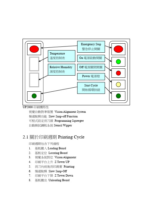
2.1關於印刷週期Printing Cycle印刷週期包含下列過程1.基板搬入Loading Board2.基板定位Locating Board3.視覺系統對位Vision Alignment4.印刷平台上升Z Tower UP5.刮刀向前後刮印錫膏Printting6.慢速脫模Slow Snap-Off7.印刷平台下降Z Tower Down8.基板搬出Unloading Board2.2硬體2.2.1操作介面軌跡球或螢幕(Trackball or Monitor)Trackball軌跡球:1.移動螢幕上的指標↖2.移動各軸3.數入數字、參數等等…..3.軟體介面開機後,顯示如下的畫面For 7.0以上(因軟體版本新舊不一樣而不同) Ultraprint 2000內全部馬達,都是步進馬達,所以剛開機必需RESET重新回原點後才能開始使用。
啟動鋼板固定鈕啟動真空馬達鈕啟動刮刀座固定鈕啟動溶劑幫浦鈕啟動前後刮刀座鈕啟動照鋼板燈泡鈕啟動照基板燈泡鈕啟動捲紙馬達鈕3.1.1下拉式功能表 Print1.Auto Print 自動印刷,機器會做印錫膏的動作Press SELECT to begin or(按SELECT 開始自動印刷)Next to change Cycle Limits : No Limit 如下圖(按NEXT,以更換印刷片數:不限制)---Print Cycle Limits--- (印刷週期設定)---Print Cycle Limits--- Roll Trackball To Change Value Print Cycle Limit : 3 Press Exit When Done.Roll Trackball To Change Value (滾動軌跡球,以變更印刷片數) Print Cycle Limit : 3 (限定印刷週期: 3片)最高999片 Press Exit When Done. (當設定完成後,按EXIT)暫時停止印刷按鈕啟動加錫膏按鈕※(必須在設定第2頁Enable Buttons 內將Dispense 打開為Yes)Press SELECT to raise squeegee (按SELECT 後刷刀會上昇,以便產生 to allow move room when adding paste, 足夠空間,讓操作員加錫) or Press NEXT to continue (按NEXT 後在原地,讓使操作員加錫) 啟動一次擦拭鋼板按鈕 ※(必須在設定第2頁Enable Buttons 內將Wiper 打開為Yes)進入生產統計過程資料視窗按鈕2.Manual Print 手動印刷,機器會做印錫膏的動作3.Pass Through 將機器當做輸送帶4. Demo Print 展示印刷模式5.SPC Data 生產統計過程資料PAUSE DISPENSER PENDINGWIPER PENDING SPC DATAPress SELECT to raise squeegee to allow move room when adding paste, or Press Next to continue顯示機器在印刷時所花的時間,如有擦拭,時間必加長機器在印刷時所等待送板與出板時間顯示PCB板進入印刷位置與鋼板對位時X、Y 、THETA 軸修正值視覺系統辨別PCB 板與鋼板Mark 點亮度接受值顯示圖表視覺系統辨別PCB 板與鋼板Mark 點X 、Y 修正補償顯示圖表2D 錫面覆蓋率檢查顯示圖表(需有此項功能才能顯示)3D 錫膏厚度檢查顯示圖表(需有此項功能才能顯示)顯示機器內的溫度(需有ECU 溫溼度監控配備此項功能)顯示機器內的濕度(需有ECU 溫溼度監控配備此項功能)將生產統計過程資料存入磁片將生產統計過程資料全部刪除 將放大過資料與圖形向左邊移動將放大過資料與圖形向右邊移動將生產統計過程資料內(值及曲線)放大與縮小圖形回到主畫面按鈕選擇預覽生產統計過程資料Cycle Time Idle Time Correction Shape Score Alignment 2D Data 3D Data Temperature Humidy1.Teach Board重做新程式About to begin TEACH operation (開始設定操作)Press SELECT to teach a new board or (按SELECT,設定新基板)Press NEXT to continue on this board setup (按NEXT,繼續這基板的設定)按SELECT 之後,出現下列訊息視窗:CAUTION, The machine must move to (警告,設定開始前,機器必須移動到 TEACH POSITION before teach can begin ”設定位置”) The machine is now going to move. (機器即將移動)Press NEXT to Continue, or EXIT to Quit. (按NEXT 繼續, 按EXIT 離開)1.1 選擇Board Parameters 進入PCB 參數設定Hardware Required:Board ParametersCAUTION, The machine must move to TEACH POSITION before teach can begin The machine is now going to move.Press NEXT to Continue, or EXIT to Quit.BoardYXEnter Board Dimensions into setup menu. (輸入基板X 、Y 、厚度)Click on Y size to adjust Track Width. (點取Y 方向尺寸,可調整軌道寬度) Press Done when finished. (當你做完上述之步驟,按Done )點取X size ,輸入基板寬度X size ,按EXIT 完成輸入,單位mm 。
cnc2000操作手册解读
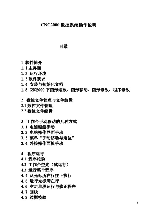
CNC2000数控系统操作说明目录1 软件简介1.1主界面1.2 运行环境1.3软件要求1.4 安装与初始化文档1.5 CNC2000下图形缩放、图形移动、图形修改、程序修改2数控文件管理与文件编辑2.1数控文件管理2.2数控文件编辑3工作台手动移动的几种方式3.1 电脑键盘手动3.2 电脑操作界面手动3.3 菜单“手动移动与定位”3.4 外接操作面板手动4 程序运行4.1 程序校验4.2 工作台空走(试运行)4.3 运行整个程序4.4 从光标所在行往下执行4.5 运行光标所在行4.6 空走单段运行与修正程序4.7 画线4.8 边框校验5 回零功能6I/O端口测试7参数设置8 数控编程8.1 自动编程8.2 视教编程8.3 手工编程9 工具栏10 其它功能10.1延时参数设置10.2 激光电源电流波形设置10.3激光电源参数设置10.4 断点恢复与断电恢复10.5 矩形零件和圆形零件焊接10.6 相贯线功能10.7 圆管切割11 配置文件设置11.1 中英文界面设置11.2默认参数设置 \Sconfig\Startdef.dat 11.3自动编程参数设置文件\Sconfig\table.dat1 软件简介CNC2000数控系统主菜单功能:文件管理、文件编辑、程序运行、手动操作、图形仿真、AutoCAD图形文件转化、查看、帮助等功能。
数控系统界面包括上、下两个用户窗口,可用鼠标拖动两个窗口中间的分界线,改变窗口大小。
上窗口为文件编辑窗口,用于进行文件管理与编辑;下窗口为文件执行窗口。
快捷键F9 暂停F11 回退F12 继续ESC 停止1.1主界面1.2 运行环境CNC2000数控系统软件基于Windows操作系统,可在Win2000、WinXP、Windows98、Windowsme或Windows95下运行。
系统设置:在电源使用方案设置中,将系统等待,关闭监视器,关闭硬盘等全部设置为:从不。
计算机不能按装实时性很强的软件,如病毒实时监控软件等,以免影响CNC系统实时运行。
Speed2000中文手册

c.当 A 线段 a1 端点与 b2 点重合时,在重合点出现较大的、闪烁的十字形光标,此时松开“Ctrl”键; 两线已经和成一条线了
d.检查结合:使用移动功能,任意选择一个端点进行移动操作,A 线和 B 线现在是一起移动了
注意:在 SPEED 2000 中术语“Package”,可以是一个 IC 的封装,也可以是指印刷电路板。任何不是属 于电路元件的东西都认为是 Package。
1
第一章
SIGRITY SpeedXP 实用手册参考
本章试图通过一个例子的分析、操作使用户对 Speed 2000 的使用、性能有一个较为直观的理解。建 议用户首先根据此例一步步的进行操作,从中领会、理解、掌握 Speed 2000 的性能以及使用方法。
2.2.8 设置网格
当为一个微分等式求解的时候,通常我们会用数字网格(numerical mesh)将一个连续的问题空间进 行分割。这样一来,我们的数字化计算技术只需要考虑分割后离散的数据点上的变量,而不是整个连续的 问题空间了。在 speed2000 中,我们使用统一的矩形网格分割金属板上连续的电压和电流变量。举个例子, 在计算中,从逻辑上讲,每个过孔(via)应该对应与它最邻近的网格点,但是,如果网格比较粗糙(格点 比较大),那么有可能出现两个或者两个以上的路由对应同一个网格点。speed2000 目前将这种情况归为 “离散错误”。用下面的步骤可以检查和解决“离散错误”。
6
SIGRITY SpeedXP 实用手册参考
是说该层上所有的导线颜色都以红色显示,点击 OK 后退出。
双击该层
出现该层的参数设置窗口
斯达特系统说明书

操作编程说明书SH-2000H 火焰切割机 数控系统 邮 编:100043 通信地址:北京石景山区阜石路166号泽洋大厦604室 电 话:(010)88799803、88909150 售后服务:(010)88799875 传 真:(010)88909271 网 址: 电子邮箱:stat@ 北 京 斯 达 微 步 控 制 技 术 有 限 公 司*使用系统前请认真阅读本手册。
使用注意事项:1. 包装箱打开后请检查系统在运输过程中有无破损,装箱单上所列内容与箱内物品是否符合。
2.本说明书适用于火焰切割机数控系统、等离子切割机、水刀切割机数控系统。
3. 请检查电源电压是否正确(AC220V±15%),并使用隔离变压器或其它有隔离功能的稳压装置。
以确保系统可靠工作和人身安全。
4.数控系统要求工作环境温度为0℃- +40℃,相对湿度为0-85%。
在高温、高湿和有腐蚀性气体的环境下工作,需要采取特殊的防护。
5.数控系统各部分接线要正确,地线接触良好。
在与等离子电源同时使用时必须有很好的接地与屏蔽。
6.数控系统不允许带电插拔机箱后部所有电缆插头,由此产生的后果,本公司拒绝保修。
7.数控系统后部输出插头的线不允许和+24V电源短路,否则将烧毁数控输出电路。
8.在高粉尘环境下,整机需要做粉尘防护,并且需要定期清理灰尘,尽量保证数控系统的清洁。
9.数控系统应由专人管理,对操作人员应进行培训。
10.不允许将数控系统内部使用的交流/直流电源连接到其他用电器。
11.本系统装载的图形编程软件为检测和征求意见版,需要在使用中完善,不作为系统必备功能和验收项目。
在使用中发现问题请及时告诉我们。
12.如遇问题,请与北京斯达微步控制技术有限公司联系。
切勿在不熟悉的情况下自行拆装、改造系统。
13.维护系统和机床,每班执行一次[日常维护和检查];每月执行一次[二级维护];每六个月执行一次[一级维护]。
详细内容见附录。
14.数控系统的各项参数严格按照本说明书或订货时的补充说明里规定的范围,超出规定的范围会使系统工作不正常甚至损坏本数控系统。
卡瓦气动洁牙机2000N使用说明书cn
插入工作头 将工作头插入转矩扳手时,要确保工作头的末端 始终向下插入转矩扳手中,否则可能造成伤害。
使用转矩扳手 使用转矩扳手更换 SONICflex 2000 N 的工作头,保护人 员免受伤害。为了快速拧上工作头,应握住转矩扳手后 部较细的手柄区域(1)。直径较大的部分(2)用于拧 紧和拧松工作头。
4105716931retro管峡左侧5605717322管峡右侧5705717332小圆柱状左侧1605715541小圆柱状右侧1705715581t形小左侧2005715521t形小右侧2105715561前牙5505717342更多的使用和安全建议如果相当长的时间内不使用sonicflex2000n定标器则必须根据这些说明进行清洗和油脂润滑保护
附件
由您所在的牙科部门提供。 名称 转矩扳手 硅油 喷嘴针 仪器架 2151 纤维垫:每包 100 个
工作头名称
scaler
clean rootplaner
bevel angle
通用 镰状 牙周 Perio 加长 刷子固定器 小芽,左侧 小芽,右侧 小芽,通用 大芽,牙周 斜角 斜角 倾斜末梢 倾斜的齿弓中线
为了避免问题责任的不明,我们建议您仅使用原 装的 KaVo SONICflex 工作头。
重要注释
SONICflex - 只能在牙科内用于治疗方面,其他任何形式的误用或错用都是禁止的,否则可能造成危险。 - 符合所在国家适用法律规定的医疗设备。 要遵循这些规定,SONICflex 只能由胜任的人员用于所述的应用,且要遵守下列注意事项: - 有关工作安全的有效规定 - 有效的事故预防措施 - 操作说明 要遵循这些规定,用户应该:
外部和内部消毒 请使用 Miele 高温消毒器 G 7881。 请按照制造商提供的用户说明操作。 必需使用 KaVo 提供的清洗产品和清洗系统立即进行清洗,确保本产品能够正常运行。
Kinetix 2000 集成轴模块和轴模块安装指南
模块安装顺序
最高 集成轴模块 2093-AC05-MP5
电源利用率或安培值
轴模块 2093-AM01
轴模块 2093-AMP2
最低
分流模块 填槽模块 2093-ASP06 2093-PRF
2093-PRS7 七轴电源导轨 (电源底板) 注意:为了避免因电击而导致人身伤害,请在电源导轨(电源底板)上的所有空插槽中放置填 槽模块 (产品目录号为 2093-PRF)。只要存在未连接模块的电源导轨接头 (插头),就会禁用 Kinetix 2000 驱动器系统;不过,控制电源仍然存在。
安装凸片
驱动器状态 通信状态 总线状态
I/O 和辅助反馈 (IOD/AF) 接头 (插头)
马达反馈 (MF) 接头 (插头) 轴模块,正视图 (所示为 2093-AM0x)
罗克韦尔自动化出版物 2093-IN001B-ZH-P - 2013 年 7 月
8 Kinetix 2000 多轴伺服驱动器
接头 (插头)说明
(CED)、马达电源 (MP) 和马达制动器 (BC) 的接线插头
• 相关安装指南,出版物编号 2093-IN001
• 马达电源 (MP) 和马达制动器 (BC) 的接线插头 • 相关安装指南,出版物编号 2093-IN001
提示
未提供马达反馈接头 (插头)套件 (产品目录号 2090-K2CK-D15M)以及辅助反馈和 I/O 接头 (插头)套件(产品目录号 2090-K2CK-COMBO)。更多信息,请参见 Kinetix Motion Accessories Specifications Technical Data (出版物编号 GMC-TD004)。
斯贝克2000N-SY智能伺服压力校验台
斯贝克SPMK2000N-SY智能伺服压力校验台(四合一)斯贝克SPMK2000N-SY智能压力校验台是我公司最新研发的专利产品,(专利号:200920108335.x),此产品是信息化,模块化管理,多项专利技术的集合。
双液压设计,升降压伺服控制。
真空、气压、双液压四合一,数字机械控制。
高准确度压力测量,选用世界一流公司的控制元件,新颖独特的造型,不锈钢超豪华台面,更完善的人机工程设计和强大的计算机软件组成了国际领先的智能压力校验系统。
本产品采用优质进口不锈钢,国外先进的密封技术,特殊的加工工艺,是各行业检定精密压力表、普通压力表、压力(差压)变送器、压力传感器、压力开关、等各种压力仪表的最理想设备。
主要用于航空、航天、军工、冶金、电力、石油、化工、食品(深加工)、制药、计量机构及仪表制造企业等单位的计量部门校验仪器仪表使用。
斯贝克压力校验台:/斯贝克压力校验台主要特点◆四合一双液压设计,水压、油压独立工作,互不影响◆采用四块标准显示仪表,可同时显示压力、电压或电流◆可提供压力、电压、电流、压力开关测量和直流24V输出,方便用户检定压力变送器,数字压力计或其他压力类仪表◆标准配置中含8支压力模块,采用瑞士keller公司芯片,长期稳定性好◆液压部分采用气驱液技术,伺服阀控制无级调压,控压速度极快。
◆高压力造压泵,大排量静音设计。
◆气体高压部分,采用增压技术,伺服阀控制无级调压。
◆完全自动造压,动态平衡技术,压力瞬间稳定,绝对无泄漏。
◆高精度进口调压阀,通过导向阀控制主阀动作实现伺服机构的高增益。
◆结束了开关截止阀及螺旋升降压的历史,极大地提高了工作效率。
◆可同时检定多只仪表,降低了劳动强度。
◆快速连接输出端口,进口密封件,长寿命,无堵塞。
◆领先世界的设计技术,安全可靠,坚实耐用。
◆环境温湿度实时监测◆可与计算机进行数据通讯,打印检定记录和检定结果。
◆配有铝合金便携箱,方便用户送检◆提供提供权威机构计量检定证书斯贝克压力校验台技术指标◆造压范围:水压(0~60)MPa 油压(0~60)Mpa(最高可做到160Mpa,需预定)真空(-0.098~0)MPa 气压(0~4)Mpa (最高可做到10Mpa,需预定)◆控压方式:全部采用进口高精度伺服调压阀控制,快速升降压,压力瞬间稳定◆传压介质: 空气、变压器油、纯净水◆可控精度:真空、气压 0.5kPa 液压 0.05MPa◆稳定时间:气压、真空 2秒液压 5秒◆系统准确度:压力测量: 优于0.05%F.S(部分量程可做0.02%F.S)电流测量: (0~±30.0000)mA 最大允许误差(±0.02%RD+0.005%F.S)电压测量:(0~±30.0000)V 最大允许误差(±0.02%RD+0.005%F.S),带DC24V输出◆联机配置:戴尔380MT:奔腾双核3.2;内存2G;硬盘500G;DVD光驱;19寸液晶显示器配置HP1007激光打印机◆联机软件:★符合国家计量检定规程①JJG 52-1999 弹簧管式一般压力表、压力真空表和真空表检定规程②JJG 49-1999 弹簧管式精密压力表和真空表检定规程③JJG 882-2004 压力变送器检定规程④JJG 875-2005 数字压力计检定规程⑤JJG 544-1997 压力控制器检定规程⑥JJG 860-1994 压力传感器(静态)检定规程⑦JJG 573-2003 膜盒压力表检定规程⑧JJG 270-1995 血压计和血压表检定规程★运行在Windows2000,XP等操作系统,功能强大,便于操作★自动生成测试结果,文件和证书★具有台帐式数据库管理功能◆外形尺寸:(1450×780×1550)mm (长×宽×高)◆重量:200kg◆总功率:400W注:该设备标准配置中含8支压力模块,压力测量模块具体量程用户可根据本单位需要选配。
华为SUN2000-(50KTL, 60KTL)-M0快速指南说明书
SUN2000-(50KTL, 60KTL)-M0 Quick GuideIssue: 07Part Number: 31509315Date: 2021-05-06HUAWEI TECHNOLOGIES CO., LTD.Indicator Status DescriptionPV connection indicatorSteady green At least one PV string is properly connected, and the DC input voltage of the corresponding MPPT circuit is higher than or equal to 200 V.OffThe SUN2000 disconnects from all PV strings, or the DC input voltage of each MPPT circuit is less than 200 V.Grid-tied indicatorSteady green The SUN2000 has connected to the power grid.OffThe SUN2000 does not connect to the power municatio n indicatorBlinking green The SUN2000 receives communications data normally.OffThe SUN2000 receives no communications data for 10s.1Product OverviewIndicator DescriptionFront View(1) PV connection indicator (2) Grid-tied indicator (3) Communication indicator (4) Alarm/Maintenance indicator (5) Maintenance compartmentdoor(6) Host panel cover1.The information in this document is subject to change without notice. Every effort has been made in the preparation of this document to ensure accuracy of the contents, but all statements, information, and recommendations in this document do not constitute a warranty of any kind, express or implied.2.Before installing the device, carefully read the user manual to get familiar with product information and precautions.3.Only qualified and trained electrical technicians are allowed to operate the device. Operators should understand the components and functioning of a grid-tied PV power system, and they should be familiar with relevant local standards.4.Before installing the device, check that package contents are intact and complete against the packing list. If any damage is found or any component is missing, contact the dealer.e insulated tools when installing the device. For personal safety, wear proper personal protective equipment (PPE).6.Huawei shall not be liable for any consequence caused by violation of the storage, moving, installation, and operation regulations specified in this document and the user manual.Indicator StatusDescription Alarm/Mainte nance indicatorAlarm statusBlinking red at long intervals (on for 1s and then off for 4s)A warning alarm is generated.Blinking red at short intervals (on for 0.5s and then off for 0.5s)A minor alarm is generated.Steady redA major alarm is generated.Localmaintenance statusBlinking green at long intervals (on for 1s and then off for 1s)Local maintenance is in progress.Blinking green at short intervals (onfor 0.125s and then off for 0.125s)Local maintenance fails.Steady greenLocal maintenance succeeds.PortsSUN2000 Dimensions Mounting Bracket Dimensions(1) Cable gland (COM1, COM2,and COM3)(2) DC switch 1 (DC SWITCH 1)(3) DC input terminals (controlled by DCSWITCH 1)(4) DC input terminals (controlled by DCSWITCH 2)(5) DC switch 2 (DC SWITCH 2) (6) Cable gland (AC OUTPUT)(7) Cable gland (RESERVE)(8) USB port (USB)2Installation RequirementsInstallation Angle2.1Installation Space2.2For ease of installing the SUN2000 on the mounting bracket, connecting cables to the bottom of the SUN2000, and maintaining the SUN2000 in future, it is recommended that the bottom clearance be between 600 mm and 730 mm.●The SUN2000 mounting bracket has four groups of tapped holes, each group containing four tapped holes. Mark any hole in each groupbased on site requirements and mark four holes in total. Two round holes are preferred.●M12x40 bolt assemblies are supplied with the SUN2000. If the bolt length does not meet the installation requirements, prepare M12 bolt assemblies by yourself and use them together with the supplied M12 nuts.●The following describes how to install the SUN2000 by using support installation as an example. For details about wall-mounted installation, see the user manual.●Save the security torx wrench for later use after removing it from the mounting bracket.3Installing the SUN2000Position for saving a security torx wrenchYou are advised to apply anti-rust paint on the hole positions for protection.Installation Preparations4.14Installing CablesNo.NameModel/SpecificationsDescription 1Ground cable16 mm 2outdoor copper cable•If you choose the ground point on the enclosure for connecting a ground cable, prepare the ground cable.•If you choose the ground point in themaintenance compartment for connecting a ground cable, use an AC output cable that includes a ground cable instead of preparing an extra ground cable.2AC output power cable 35 mm 2outdoor copper cable-3OT terminal M8When using outdoor copper cables for AC connection, select copper wiring terminals. For requirements on the cables and terminals of other materials, see user manual.4DC input power cablePV cable that meets the 1100 V standard N/A5RS485communications cable (terminal block)Computer cable DJYP2VP2-22 2×2×1•If RS485 communication is used, prepare the RS485 communications cable.•A terminal block is recommended for connecting to the RS485 communications cable.RS485communications cable (RJ45 network port)Outdoor shielded network cable/CAT 5E6Cable tie N/A N/A1.Before installing cables, ensure that all required OT terminals and cables are prepared.2.The following table lists only recommended cable specifications. For more cable specifications, see the user manual.2.Open the maintenance compartment door and install the support bar.Installing the Ground Cable4.2•The ground point on the enclosure is preferred to connect to the PE cable for the SUN2000.•The ground point in the maintenance compartment is mainly used for connecting to the ground cable included in the multi-core AC power cable. For details, see section " 4.4Installing AC Output Power Cables."•The ground cable must be secured.•It is recommended that PGND cable of the SUN2000 be connected to the nearest ground point. For a system with multiple SUN2000s connected in parallel, connect the ground points of all SUN2000s to ensure equipotential connections to ground cables.•To enhance the corrosion resistance of the PE terminal, apply silica gel or paint on it after connecting the PGND cable.Opening the Maintenance Compartment Door4.31.Never open the host panel of the SUN2000.2.Before opening the maintenance compartment door, turn off the downstream AC output switch and the two DC switches at the bottom.3.If you need to open the maintenance compartment door on rainy or snowy days, takeprotective measures to prevent rain and snow entering the maintenance compartment. If it is impossible to take protective measures, do not open the maintenance compartment door on rainy or snowy days.4.Do not leave unused screws in the maintenance compartment.1.Loosen the two screws on the maintenance compartment door using a security torx wrench.3.Remove the cover and hang it on the hook of the enclosure door.1.Route the cable through the cable gland.Installing AC Output Power Cables4.4If the screws on the enclosure door are lost, obtain spare screws from the fitting bag boundto the inductor cover at the bottom of the enclosure.1.Select an appropriate rubber fitting based on the outer diameter of the AC power cable to ensure proper sealing.2.There are two types of waterproof connectors for the AC OUTPUT port. The dimensions depend on the SUN2000 that is used.3.To avoid damaging the rubber fitting, do not route a cable with a crimped OT terminal through the rubber fitting.4.Do not adjust the cable when the thread-lock sealing nut is tightened. Otherwise, the rubber fitting will shift, which affects the Ingress Protection Rating of the device.Position for saving spare screws•If you connect a ground cable to the ground point on the chassis shell in a scenario with no neutral wire, you are advised to use a three-core (L1, L2, and L3) outdoor cable.•If you connect a ground cable to the ground point in the maintenance compartment in a scenario with no neutral wire, you are advised to use a four -core (L1, L2, L3, and PE) outdoor cable.•If you connect a ground cable to the ground point on the chassis shell in a scenario with a neutral wire, you are advised to use a four-core (L1, L2, L3, and N) outdoor cable.•If you connect a ground cable to the ground point in the maintenance compartment in ascenario with a neutral wire, you are advised to use a five -core (L1, L2, L3, N, and PE) outdoor cable.3.Crimp an OT terminal.Core wireInsulation layer Heat gunHydraulic pliersHeat shrink tubingJacketInsulation layerCore wirea.Three-core cable (excluding the ground cable and neutral wire)c.Four-core cable (excluding the ground cable but including the neutral wire)b.Four-core cable (including the ground cable but excluding the neutral wire)d.Five-core cable (including the ground cable and neutral wire)2.Remove an appropriate length of the jacket and insulation layer from the AC output power cable using a wire stripper. (Ensure that the jacket is in the maintenance compartment.)L2=L1+3 mm L1L1L2=L1+3 mm ≤ 230 mm≤ 230 mmL2=L1+3 mm L1≤ 230 mmL1L2=L1+3 mm ≤ 230 mm4.Connect the AC output power cable to the terminal block, and then tighten the nut using a torque wrench that has an extension rod.a.Three-core cable (excluding the ground cable and neutral wire)c.Four-core cable (excluding the ground cable but including the neutral wire)b.Four-core cable (including the ground cable but excluding the neutral wire)d.Five-core cable (including the ground cable and neutral wire)5.Tighten the thread-lock sealing nut.6.Clear debris from the maintenance compartment.•Ensure that AC terminations provide firm and solid electrical connections. Failing to do so may cause SUN2000 malfunction and damage to its terminal block, even starting thermal events.•If the AC output power cables are subject to a pulling force because the inverter is not installed stably, ensure that the last cable that bears the stress is the PE cable.4.5Installing DC Input Power CablesSelecting DC Input TerminalsThe SUN2000 provides two DC switches, named as DC SWITCH 1 and DC SWITCH 2. DC SWITCH 1 controls the 1st to 6th sets of DC input terminals, whereas DC SWITCH 2 controls the 7th to 12th sets of DC input terminals.Select DC input terminals according to the following rules:1.Evenly distribute DC input power cables on the DC input terminals controlled by the two DCswitches.2.Maximize the number of connected MPPT circuits.Ensure that the PV module output is well insulated to ground.e the Amphenol Helios H4 PV connectors provided with the SUN2000. If the connectorsare lost or damaged, purchase the PV connectors of the same model. The device damaged caused by incompatible PV connectors is not covered under any warranty or serviceagreement.2.The metal contacts supplied with the DC connectors are either cold forming contacts orstamping forming contacts. Crimp the metal cold forming contacts using crimping toolUTXTC0005 (Amphenol, recommended) or H4TC0001 (Amphenol). Crimp the metalstamping forming contacts using crimping tool H4TC0003 (Amphenol, recommended) or H4TC0002 (Amphenol). Choose the crimping tools that fit the metal contacts.3.Before connecting DC input power cables, label the cable polarities to ensure correct cableconnections. If the cables are connected incorrectly, the SUN2000 may be damaged.4.Insert the crimped metal contacts of the positive and negative power cables into theappropriate positive and negative connectors. Then pull the DC input power cables to ensure that they are connected securely.5.Connect the positive and negative connectors to the appropriate positive and negative DCinput terminals. Then pull the DC input power cables to ensure that they are connected securely.6.If polarity of the DC input power cable is reversed and the DC switch is ON, do not turn offthe DC switch immediately or unplug positive and negative connectors. The device may be damaged if you do not follow the instruction. The caused equipment damage is beyond the warranty scope. Wait until the solar irradiance declines and the PV string current reduces to below 0.5 A, and then turn off the two DC switches and remove the positive and negative connectors. Correct the string polarity before reconnecting the string to the SUN2000.8-10 mm8-10 mmPositive connectorNegative connectorPositive metal contactNegative metal contact Recommended: PV cable that meets the 1100 V standard.Ensure that the cable cannot be removed after crimped.UTXTC0005(Amphenol)ClickEnsure that the locking nut is secured.H4TW0001(Amphenol)Use a multimeter to measure the DC voltage.ClickInstalling DC Input Power Cables (Cold Forming Metal Contact)•If the voltage is a negative value, the DC input polarity is incorrect. Correct the polarity.•If the voltage is greater than 1100 V DC, too many PV modules configured to the same string. Remove some PV modules.Installing DC Input Power Cables (Stamping Forming Metal Contact)H4TC0003 (Amphenol)H4TW0001(Amphenol)Negative metal contact Recommended: PV cable that meets the 1100 V standard.Ensure that the cable cannot be removed after crimped.Positive connectorNegative connectorClickEnsure that the locking nut is secured.Use a multimeter to measure the DC voltage.Click8-10 mmPositive metal contact8-10 mmInstalling the RS485 Communications Cable4.6 1.When routing communications cables, separate communications cables from power cables to prevent communication from being affected.2.An RS485 cable can connect to either a terminal block or an RJ45network port. It is recommended that the RS485 cable connect to a terminal block.Terminal Block Connection (Recommended)3.Remove the cable terminal base from the terminal block. Connect the communications cable to the terminal base.1.Remove an appropriate length of the jacket and core wire insulation layer from the communications cable using a wire stripper.No.Port Definition Description1RS485A IN RS485A, RS485 differential signal+2RS485A OUT RS485A, RS485 differential signal+3RS485B IN RS485B, RS485 differential signal –4RS485B OUTRS485B, RS485 differential signal –2.Route the cable through the cable gland.5.Bind the communications cable.4.Install the terminal base on the terminalblock, and connect the shield layer to theground point.When connecting the shielded cable, choose whether to crimp the OT terminal based on site requirements.6.Tighten the thread-lock sealing nut and seal the waterproof connector.RJ45 Network Port Connection1.Prepare an RJ45 connector.2.Route the cable through the cable gland.No.Color Pin Definition1White-and-orange RS485A, RS485differential signal+2Orange RS485B, RS485differential signal–3White-and-green N/A4Blue RS485A, RS485differential signal+5White-and-blue RS485B, RS485differential signal–6Green N/A7White-and-brown N/A8Brown N/A4.Bind the communications cable.3.Insert the RJ45 connector into the RJ45 networkport in the SUN2000 maintenance compartment.5.Tighten the thread-lock sealing nut and seal the waterproof connector.5Verifying the Installation1.The SUN2000 is installed correctly and securely.Yes □No □N/A □2.The DC switches and downstream AC switch are OFF.Yes □No □N/A □3.All ground cables are connected securely, without open circuitsor short circuits.Yes □No □N/A □4.AC output power cables are connected correctly and securely,without open circuits or short circuits.Yes □No □N/A □5.DC input power cables are connected correctly and securely,without open circuits or short circuits.Yes □No □N/A □6.The RS485 communications cable is connected correctly andsecurely.Yes □No □N/A □7.Check that all used cable glands at the bottom of theenclosure are sealed, and that the thread-lock sealing nut isYes □No □N/A □tightened.8.The AC terminal cover is reinstalled.Yes □No □N/A □9.The maintenance compartment door is closed and the doorscrews are tightened.Yes □No □N/A □10.Unused DC input terminals are sealed.Yes □No □N/A □11.Unused USB ports are plugged with watertight caps.Yes □No □N/A □12.Unused cable glands are plugged and the thread-lock sealingnuts are tightened.Yes □No □N/A □6Powering On the SystemBefore turning on the AC switch between the SUN2000 and the power grid, use a multimeter to check that the AC voltage is within the specified range.1.Turn on the AC switch between the SUN2000 and the power grid.2.Turn on the DC switches at the SUN2000 bottom.SUN2000 App7Login PageWLAN or Bluetooth Connection USB Data Cable ConnectionSelect ConnectionModeSelect User Quick Settings1.The SUN2000 app is mobile phone app that communicates with the SUN2000 monitoring system over a USB data cable, Bluetooth module, or WLAN module. As a convenient local monitoring and maintenance platform, itsupports alarm query, parameter configuration, and routine maintenance. The app name is SUN2000.2.Log in to Huawei AppGallery (https://), search forSUN2000, and download the app installation package. You can also scan the QR code (https:///appdl/C10279542) to download the installation package.3.Connect a USB data cable, a Bluetooth module, or a WLAN module to the USB port of the SUN2000 to implement the communication between the SUN2000 and the app.●The screenshots in this document correspond to app version 3.2.00.013(Android).●When the WLAN connection is used, the initial name of the WLAN hotspot is Adapter-WLAN module SN , and the initial password is Changeme .●The preset passwords for Common User , Advanced User , and Special User are 00000a .●Use the initial password upon first power-on and change itimmediately after login. To ensure account security, change the password periodically and keep the new password in mind. Not changing the initial password may cause password disclosure. A password left unchanged for a long period of time may be stolen or cracked. If a password is lost, devices cannot be accessed. In these cases, the user is liable for any loss caused to the PV plant.●Set the correct grid code based on the application area and scenario of the solar inverter.Main menu screenBefore installing the module, configure the communication parameters of the host on the SUN2000app. For detailed configuration, see the user manual.8(Optional) Installing a 4G ModuleThe 4G communication mainly applies in the distributed PV plants with a small number of inverters. The inverters directly connect to the FusionSolar management system through the 4G network.•If the 4G communication is used, a maximum of 10 SUN2000s can be connected.•Install the 4G module on the SUN2000master.The RS485communication is used between the SUN2000master and slave, and between the SUN2000slave and slave.1.Press the buckle inwards to remove the 4G module enclosure, and then install the SIM card.•If the 4G module you purchase is configured with a SIM card, skip this step.•If it is not configured with a SIM card, prepare a standard one (dimensions: 25 mm x 15 mm, capacity ≥ 64 KB.•When installing a SIM card, you can determine the SIM card installation direction based on the silk screen and arrow mark on the slot.•When being pressed into place, the SIM card will be locked, which means that the card is installed correctly.•To remove the SIM card, push it inwards. Then the SIM card springs out automatically. •When reinstalling the 4G module enclosure, ensure that the buckle springs back to the original position.2.Remove the watertight cap from the USB port and fix the 4G module.Huawei Technologies Co., Ltd. Huawei Industrial Base, Bantian, Longgang Shenzhen 518129 People's Republic of China。
- 1、下载文档前请自行甄别文档内容的完整性,平台不提供额外的编辑、内容补充、找答案等附加服务。
- 2、"仅部分预览"的文档,不可在线预览部分如存在完整性等问题,可反馈申请退款(可完整预览的文档不适用该条件!)。
- 3、如文档侵犯您的权益,请联系客服反馈,我们会尽快为您处理(人工客服工作时间:9:00-18:30)。
2. 参考Installation and Operation Manual 附录 E:SVS2000结构尺寸图纸,在安 装位置开孔。
3. 将SVS2000牢固可靠地固定在安装孔 内。
4. 安装SVS2000时,请小心使用客户提供 的硬件设备。
5. 安装不锈钢外壳版本时,从外壳底部固 定好设备后,再安装先前拆下的电子部 件。
19200) 53 PLC菜单[PLC Menu]
A-B RIO Menu DeviceNet Menu (release 1st quarter 1999)
Profibus Menu (release in 1999)
Modbus Menu (release in 1999)
60 传感器菜单[Sensor Menu]
密封胶密封SVS2000。 6. SVS2000接线的紧固力矩为8 lbf/in (1N/m)。
警告
• 接线必需符合当地国家/地方接线标准。 • SVS2000必需做到可靠接地,接地电阻须小于4
欧姆。 • 电源配线必需配备开关/断路器,开关/断路器需要
靠近操作者并有明显标识,以便紧急时刻切断电 源。
1
使用快速配置设置
1. 见图1和图2。确定应用方案是直接支撑式还是贴
片式。搜集并填写图1和图2表格中所需要的技术 参数。
2. 见图3,执行快速配置设置,SVS2000会引导你按
照菜单树的顺序配置所需参数。当快速配置完成 后,SVS2000将会自动切换到运行模式。
直接支撑式传感器[Direct Support]?
手册。 2 输入容器支撑腿的数量,而不是传感器的数量。比如:
在上图所示的应用中,有 3 个支撑腿(容器的所有重力
都由此 3 个纵向支撑件承担),但是仅有 2 个支撑点安
装了传感器,这里的“垂直支撑腿的数量”应该为 2 个。
图 1. 直接支撑式(传感器)方案 2
KM 贴片式传感器[KM Bolt-On]? 单位[Units]? lbs 或者 kg 传感器型号?1 Microcells 或者 L-Cell 使用 Microcell 传感器 1,2:
图 3. 快速配置菜单树和按键说明
运行模式和功能模式
• 运行模式-SVS2000正常工作状态 显示毛重、净重、总重和继电器状态。
• 功能模式-菜单树 • 访问菜单树,参看或者修改参数配置。 快速配置完成后,SVS2000将会自动切换到运行模式。
运行模式
*简要显示
二种模式切换模式 Gross键
(返回到毛重显示状态) 或者
80 跟踪菜单[Tracking Menu]
81 Rate Threshld
82 Sample Intrvl
83 Zero Trak Win
84 Drift Limit
85 Mat Trak Enab (On Off)
89 Rate Monitor
90 服务菜单[Service Menu]
91 用户登陆密码[User Access] 92 键盘锁[Keyboard Lock] 93 键盘测试[Keyboard Test] 94 恢复出厂参数[Default Systm] 99 诊断[Diagnostics]
11 显示格式[Disp Format] (xxxxxx xxxxx.x xxxx.xx xxx.xxx xx.xxxx xxxxxxo xxxxxxoo)
12 显示计数[Disp Countby] (1 2 5 10 20 50 100 200 500 1000 5000 10,000)
13 显示单位[Disp Units] (lbs kg CWT tns gal Ltr bbl
24 清零范围[Zero Tolerance] 29 校正参数显示[Cal Display] (Cnt/mV, ScfWgt,
ScfCnt, ZeroCnt, DispVCW, HiSpanW, LoSpanW, HiSpanC, LoSpanC, 0mV_Cnt)
30 预置点菜单[Setpoint Menu]
图 2. 贴片式(Microcell or L-Cell)方案
Enter 键――选择参数或者保存参数
Func 键――返回到上一级参数配置选项
上下方向键――在菜单中上下翻页选择所需参数
Gross 和 Net 键--取消快速配置返回到运行模
数字键――输入数字
式(按照 SVS2000 内置默认参数运行)
单位[Units]? lbs 或者 kg 单个传感器容量[Cell Rated Load]?1
lbs 或者 kg 灵敏度[Sensitivity]?1
mV/V 垂直支撑腿数量[# of Supports]2
当前加载重量[Current live Load]?
备注:
lbs 或者 kg
1 传感器的详细技术参数详见传感器标签或者传感器
预置点测试[Setpoint Test] Select Relay #1 (Off On), Select Relay #2
(Off On) Select Digtl #1 (Off On), Select Digtl #2
(Off On), Select Digtl #3 (Off On), Select Digtl
4
菜单描述
10 显示菜单 Display Menu • 11 显示格式[Disp Format] -移动小数点或者添加”0”来显示,和Dips Countby配合 使用来显示输出结果。注意,修改本参数会影响后续很 多参数的值。 • 12 显示计数[Disp Countby] -设定显示增量 • 13 显示单位[Disp Units] -设定显示称量单位 • 14 条形图跨度[Bargraph Span] -设定条形图100%所对应的值 15 外部输入模式[EXT Input mode] -设定外部输入信号是作为远程去皮还是远程累计
Net键 (返回到净重显示状态)
切换到 运行模式
功能模式(菜单ห้องสมุดไป่ตู้和功能描述详见下页)
切换到 功能模式
Func键 (进入菜单树10) 或者 输入菜单树对应数字键和Enter键 (进入对应的菜单树)
备注:使用方向键和 Enter 键进 入其它菜单方法类似。
3
功能模式菜单树
10 显示菜单[Display Menu]
20mA Point) 49 输出测试[Test Current] (4/0mA 6/2mA 8/4mA
10/6mA 12/8mA 14/10mA 16/12mA 18/14mA
20/16mA –/18mA –/20mA)
50 通讯菜单[Com Menu]
51 串口节点地址[Serial Address] 52 波特率[Serial Baud] (1200 2400 4800 9600
lbs 或者 kg 容器的最大压强[Working Stress]?
psi 或者 kg 当前加载重量[Current live Load]?
lbs 或者 kg
备注:
1 传感器的详细技术参数参见产品样本,样本可以向 KM索取。 2 快 速 配 置 中 的 校 正 参 数 是 针 对 3-inch 规 格 的 Microcells 应用在碳钢上的情况。如果3-inch规格的 Microcell应用在不锈钢或者 铝制材料上,或者 使用 2-inch规格的Microcells,请在快速配置完成后手动修 改校正参数。见手册附录 C:手动校准参数的计算, 以获得更加详细的信息。
22 手动校正 [Manual Cal] 重量因子[Scale Factor Wgt] 内分度因子[Scale Factor Cts] 零点输出[Zero Counts]
23 线性[Linearization] 线性设定[Linearize Set] 线性允许[Linearize Enable] (Off,On)
接线
请将交流电源线、预置点控制线和低压信号线分至于 不同的走线线路中,以免对低压传感器信号产生干扰。 1. 连接传感器线。 2. 连接继电器输出,数字输出,模拟量输出,串口输
出,和远程输入信号线(如有)。 3. 连接交流电源线。 4. 打开电源检查仪表显示。 5. 使用Sikaflex 1A或者Dow Corning RTV 739 or 738
31 选择#1继电器[Slct Relay #1] 目标重量[Relay1 Value] 死区[Relay1 Deadband] 高于/低于[Relay1 Hi/Lo (Hi Lo)] 目标重量来源[Relay1 Track (Grs Net Tot Flt)] 故障-安全[Relay1 Fail-Safe (On Off NC)] 提前量[Relay1 Preact]
61 传感器激励电压调整[Sensor Adj Ex] (13V 12V
11V 10V 9V 8V 7V 6V 5V) 62 分辨率[Resolution] (16bt 17bt 18bt 19bt 20bt
21bt) 63 传感器增益[Sensor Gain] (1 2 4 8 16 32 64 128) 69 传感器输出显示[Sensor Disply] (Raw Weight,
Ftr Weight, Out Weight, Raw Counts, Ftr Counts,
Sensout)
70 滤波菜单[Filter Menu]
71 平均[Averaging] 72 DSP允许[DSP Enable] (On Off) 73 DSP步进[DSP Step] 74 DSP数量[DSP Qualify] 75 DSP因子[DSP Factor] 79 DSP调整监控DSP Step Mon
bu % ft m mV none) 14 条形图跨度[Bargraph Span] 15 外部输入模式[Ext Input mode] (Tare, Total)