
5B-3B(V8.3) 说明书X
5B-3B 型(V8.3 版)多参数水质分析仪
第4页
共 45 页
连华科技
LIANHUA TECHNOLOGY
因为专一 所以专业
Therefore,because the single-minded professional
第一节
引
言
尊敬的用户:您好! 感谢您选用我公司研制生产的碧月牌 5B-3B 型( V8.3 版)多参数水质分析仪。为确保正确使用仪器, 请在使用前仔细阅读本手册。 化学需氧量( Chemical Oxygen Demand )简称 COD 。是在一定的条件下,采用一定的强氧化剂处 理水样时,所消耗的 氧化剂量。它是表示水中还原性物质多少的一个指标。水中的还原性物质有各种有 机物、亚硝酸盐、硫化物、亚铁盐等,但主要的是有机物。因此,化学需氧量( COD )又往往作为衡量 水中有机物质含量多少的指标。化学需氧量越大,说明水体受有机物的污染越严重。 本仪器采用一种特制试剂,它含有一种复合催化剂,既加速反应,又对氯离子具有抗干扰作用。水样与特制 试剂在消解器中进行快速氧化还原反应,反应后产生三价铬离子,通过分光光度法测定其浓度,从而得出相应 COD 值。 我公司在二十世纪八十年代初,就发明了快速测定污水中化学需氧量 (COD)的方法---催化快速法。并在 国内首家研制出第一代实验室用 COD 速测仪,用以替代长期以来国内外普遍使用的“两小时回流消解、滴定求 值”的测定方法。使其具备快速、低耗、简便、准确、可靠等特点,将测定 COD 需用三到四个小时的传统方法 变成历史。 我们本着:在严格遵循传统法科学性的基础上,对烦琐的实验步骤进行了合理的优化。通过我公司的多年努 力,目前我公司的测定仪系列产品检测数据,不但与传统法可比,而且大大简化了实验过程和时间。 5B-3B 型(V8.3 版)多参数水质分析仪是我公司的第八代产品,完全依据国家新法规《快速消解分光光度 法(HJ/T 399-2007)》设计制造,适用于国内外众多检测标准。专门根据我国水质情况及国家法规要求而开发的一 款能同时测量 COD、氨氮、总磷、浊度等多种参数的高档测定仪,此仪器性能稳定、准确度高、测量范围宽、 显示清晰、测量迅速、使用简单方便,其配套的高档智能消解器使测试过程更加安全可靠。 5B-3B 型( V8.3 版)多参数水质分析仪为实验室智能型测定仪,精度高,寿命长,更稳定。在测 COD 之 外,还具有测定氨氮、总磷的功能,并可扩展测定水中大多数污染物,同时支持比色皿(池)和比色管两种比色方 式;兼具智能数据分析功能,图表、列表显示数据,分析一目了然;高清晰度彩色液晶显示屏,中文显示界面, 全中文键盘,人性化操作提示,使用更简单。能够广泛的应用于各种行业(工业废水、城市污水、生活污水及江 湖流域地表水)废水的检测。可适合不同用户的多种需求,可在化工、石油、焦化、造纸、冶金、酿造、医药等 工业废水及各种生活污水监测应用。 连华人将在以后的成长中,凭借雄厚的技术力量和优秀的工作团体,回报广大用户的支持。我们本着以卓越 的科技立足行业、以优质的服务赢得客户、以共同的追求汇聚英才、以完善的管理求得飞跃的宗旨,为创造一个 节能减排的和谐社会贡献自己的力量。
连华科技
LIANHUA TECHNOLOGY
因为专一 所以专业
Therefore,because the single-minded professional
多参数水质分析仪 5B-3B 型(V8.3 版)使用说明手册
声 明 Copyright ⓒ 2008 兰州连华环保科技有限公司 版权所有·保留所有权利 版本:20110609.1 为兰州连华环保科技有限公司的注册商标。本手册所提及的其他所有商标或注册商标, 由各自的所有人拥有。 本手册所提到的产品规格和资讯仅供参考,如有内容更新,恕不另行通知。
5B-3B 型(V8.3 版)多参数水质分析仪
第1页
共 45 页
连华科技
LIANHUA TECHNOLOGY
因为专一 所以专业
Therefore,because the single-minded professional
目
录
安全警示和注意事项 …………………………………………………………………3 免责及质保 ……………………………………………………………………………… 4 一 二 引 言 ……………………………………………………………………………………… 5 技术参数及性能指标 …………………………………………………………………6 1.性能参数 ………………………………………………………………………………6 2.物理参数 ………………………………………………………………………………6 3.环境及工作参数 ………………………………………………………………………6 4.扩展测定项目………………………………………………………………………… 6 三 四 随箱物品介绍 ………………………………………………………………………… 8 首次使用前的准备工作……………………………………………………………… 11 1.随箱物品清点…………………………………………………………………………… 11 2.实验物品准备…………………………………………………………………………… 11 3.试剂配制……………………………………………………………………………… 11 五 快速入门………………………………………………………………………………… 13 1.仪器简介…………………………………………………………………………… 2.水样测顶…………………………………………………………………………… 14 14
二.质保
1. 本公司对所有产品在出厂前,都进行了严格的产品检验,并对所有制造和质量上的问题,自出厂之日起 免费保修一年。 2. 如在仪器质保期内,因不规范的操作、不符合要求的使用环境、人为过失、意外事件、不当的存储或运 输原因造成的问题,我公司仍负责维修,但需根据仪器故障程度收取适当的成本费用。 3. 对于超过质保期的仪器,本公司将采取有偿保修和服务。 4. 当发生以下情况之一时,该产品将不再受到连华公司的保修及服务: (1)一切将仪器分解、再组装、拆机或改造的行为; (2)非我公司直属机构及授权的人员,擅自维修过的仪器; (3)产品防拆机易碎膜破裂的仪器; (4)未使用厂家原装耗材而造成仪器测定故障的仪器; (5)通过非正常渠道购买到的我公司产品。
仪器中配带的固体试剂, 应在干燥、 密封、 避光、 低温条件下储存。
仪器使用结束后, 用于比色的废液, 应集中存储 并处理,不要随意搁置或倾倒。 使用过程中比色溶液,如果粘到皮肤或衣服上, 请立即用大量清水清洗。以免对皮肤造成伤害。
5B-3B 型(V8.3 版)多参数水质分析仪
第3页
共 45 页
5B-3B 型(V8.3 版)多参数水质分析仪
第5页
பைடு நூலகம்
共 45 页
连华科技
LIANHUA TECHNOLOGY
因为专一 所以专业
Therefore,because the single-minded professional
第二节
1 性能参数:
1) 2) 3)
技术参数及性能指标
控温范围:45~190℃ 批处理样:15/30(选配) 抗氯干扰:[Cl-]<1000mg/L [Cl-]<10000mg/L(可选) 4) 波长范围:420nm、460nm、510nm、560nm、610nm、700nm 5) 曲线数量:330条 6) 存储数据:12000个 7) 定时模式:自动延时 8) 显示模式:彩色液晶屏 9) 操作按键:中文/英文(可选) 10) 参数切换:自动
被禁止的操作
需要注意的操作
必须强制的操作
禁止进行拆卸
将插头从插座中拔出
以下规定是安全警示和注意事项,是必须遵守的规定:
请勿在高湿、高温或灰尘多的地方存放或工作, 以免造成仪器硬件故障。 仪器及备件不具备防水功能,应防止被水淋湿 等情况发生。 避免强烈碰撞、震动,可能导致仪器光路损坏。 在搬运过程中建议使用仪器原包装。 禁止仪器在腐蚀性气体的空间中工作,以免造 成电路系统的损坏。 请勿在湿手时插拔仪器电源线,以防止触电的 可能。 请勿在强光直射的情况下使用该仪器。勿将肢 体与消解仪加热部分直接接触小心烫伤。 请勿擅自拆开仪器进行维修或更改其内部结 构,以防事故及故障的发生。 在仪器使用过程中,如果出现硬件异常情况或 软件操作故障时,应尽快与厂家技术部门联系, 请勿擅自对仪器进行维修拆装。 当水或其他液体不慎进入仪器后,请马上关闭 仪器,并将电源插头从插座中拔出。 消解仪如发生喷溅或反应管破裂,请马上关闭 电源,并将电源插头从插座中拔出。 在实验过程中必须做好个人防护工作(实验服、 手套、眼罩、口罩) ,使用硫酸时注意个人安全。 如果电源线已损坏 (导线外露或断裂) 请勿再使 用,以免引起触电。 在用仪器进行比色时, 勿将比色溶液溢漏到仪器 的比色池中,以防导致光路系统的腐蚀损坏。 用比色皿比色时, 需将比色皿外壁的水渍及残留 溶液擦拭干净,否则会导致测定结果出现偏差。 请仔细阅读本手册, 在掌握了仪器的各个功能及 注意事项后,再进行操作。 在对测定水样进行消解加热时, 请务必加盖仪器 中配备的防喷罩,确保操作安全。 在对水样进行分析时, 水样中加入试剂后必须混 匀再进行消解,否则消解时将造成溶液的喷溅。
(1)污水 COD 的测定………………………………………………………………… 14 (2)地表水 COD 的测定……………………………………………………………… 18 (3)预置试剂法测定……………………………………………………………… 19 (4)氨氮的测定…………………………………………………………………… 21 (5)总磷的测定…………………………………………………………………… 24 六 仪器基本操作及功能介绍…………………………………………………………… 27 1.5B-1 型 (V8.0 版)消解器介绍………………………………………………………… 27 2.5B-3B 型(V8.3 版)多参数水质测定仪介绍 …………………………………………31 七 仪器校准及标定 ……………………………………………………………………… 36 1.标准溶液的配制………………………………………………………………………… 36 2.标准溶液的预处理 ……………………………………………………………………37 3.曲线值的校准 …………………………………………………………………………38 八 曲线的应用 ……………………………………………………………………………… 40 1.备用曲线的应用 ………………………………………………………………………40 2.拟合曲线的应用 ………………………………………………………………………40 九 附件 1 故障分析与排除 ……………………………………………………………………… 43 打印纸更换方法 ……………………………………………………………………… 45
日立 ZW80-5B 轮式装载机 产品手册说明书

ZW-5b series44 hp 32.8 kW
Engine Output, Max, Gross (ISO 14396)
9,350 lbs 4,240 kgOperating weight42 hp 31.8 kWEngine Output, Max, Net (ISO 9249)0.8 yd³ 0.6 m³
Bucket capacityTier 4 Final Certified
66 hp 49 kW
Engine Output, Max, Gross (ISO 14396)
12,600 lbs 5,715 kgOperating weight63 hp 47 kWEngine Output, Max, Net (ISO 9249)1.2 yd³ 0.9 m³
Bucket capacityTier 4 Final CertifiedZW50‑5b / ZW80‑5b
10. INCREDIBLE VERSATILITY6. FIRST FOR RELIABILITY8. DEDICATED TO COMFORT AND SAFETYNO COMPROMISEOffering exceptional levels of performance without compromising on efficiency, Hitachi ZW-5b wheel loaders are designed to satisfy the requirements of the North American construction industry.
Designed to be reliable, durable and versatile for a variety of job sites, and to operate with low levels of fuel consumption, they incorporate the high-quality engineering for which Hitachi is renowned.
3B SCIENTIFIC 气体放电管说明书

3B SCIENTIFIC ® PHYSICSInstruction sheet06/16 ALF1 Tube holder S (not in-cluded)2 4 mm contact pins3 Glass tube with pump nozzles4 Holder5 End cap with fluorescent screen6 T tube connector7 Vent valve 8Vacuum hoseDischarge tubes are capable of producing X-rays at operating voltages ≥ 5kV .∙ Do not operate the discharge tubes with voltag-es in excess of 5 kV.The discharge tube is a thin-walled glass tube. A damaged tube may implode when evacuated. ∙ Do not subject the discharge tube to anymechanical stresses and use it with care.∙Check the tube for damage before using it in an experiment.When the discharge tube is in operation, high voltages may be present at the electrodes.∙ Do not attempt any wiring unless the powersupply is switched off.The gas discharge tube S is used for observa-tion of electrical discharges in gases under re-duced pressure as well as for investigation of cathode beams and canal rays, which appear at low pressure outside the discharge path.The gas discharge tube is a glass tube which can be evacuated and which has luminescent screens at either end. It is supplied in disman-tled form and is intended to be set up on the S-series tube holder (1014525).1 Glass tube with pump nozzles2 End caps with fluorescent screen2 Holders with sealing washers, electrodes with slotted apertures and 4-mm terminal pins1 Vent valve1 T-connector3 Vacuum hoses (2x short, 1x long)Polarization voltage: ≤ 5 kVDischarge current: 1.2 mA approx., de-pending on gas pres-sureConnections: 4 mm contact pins Tube length: 130 mm x 15 mm diam. Total length: 280 mm approx.5.1 Set-up for S-model discharge tube in S-series tube holder∙Fit the end caps into the holder (see Fig. 1).∙Slot both holders into the slit in the tube holder unit and move them all the way to the left or right (see Fig. 2).∙Insert the glass tube into the holders. In order to ensure that the glass tube is firmly held in place, push the holders slightly towards the centre (see Fig. 3).∙Connect the vent valve to the T-connector using a short hose and use the second short hose to connect the connector to theglass tube. Insert the ventvalve into the central hole in the tube holder (see Figs. 4).Fig. 1 Fig. 2 Fig. 3Fig. 45.2 Experiment instructionsTo perform experiments using the gas discharge tube S, the following equipment is also required: 1 Tube holder S 1014525 1 Rotary-vane vacuum pump, two-stage1003317 2 Experiment lead, safety plug and socket1002839 1 High voltage power supply, 5 kV (230 V, 50/60 Hz)1003310 or1 High voltage power supply, 5 kV (115 V, 50/60 Hz)1003309∙Connect the hose to the vacuum pump.∙Connect the power supply to the 4-mm ter-minal pins.∙Apply a voltage of 5 kV to demonstrate lumi-nescent discharges.∙After the operating voltage is applied, evacuate the tube and close the vent valve.∙Darken the room and observe the luminescent phenomena.∙When the experiment is finished, turn off the pump and open the vent valve to let air into the discharge tube. Gas discharge at low pressureDepending on the range of pressure, various phe-nomena may be observed when high voltage is applied:Gas discharges with various gases∙Allow a sequence of different gases into the tubes.The luminescent phenomena will differ depending on the gas used.∙Use a spectroscope to view spectral lines.Magnetic deflection of anode rays and cath-ode rays∙At pressures below 10-2 millibars, move a per-manent magnet towards the tube and observe how it deflects the rays.Due to the differing masses of the particles in-volved, the image of the slit on the fluorescent screen does not move much for the anode rays, but the cathode rays are deflected heavily3B Scientific GmbH ▪ Rudorffweg 8 ▪ 21031 Hamburg ▪ Germany ▪ 。
3B SCIENTIFIC 电压计 (230V, 50 60Hz) 产品说明书
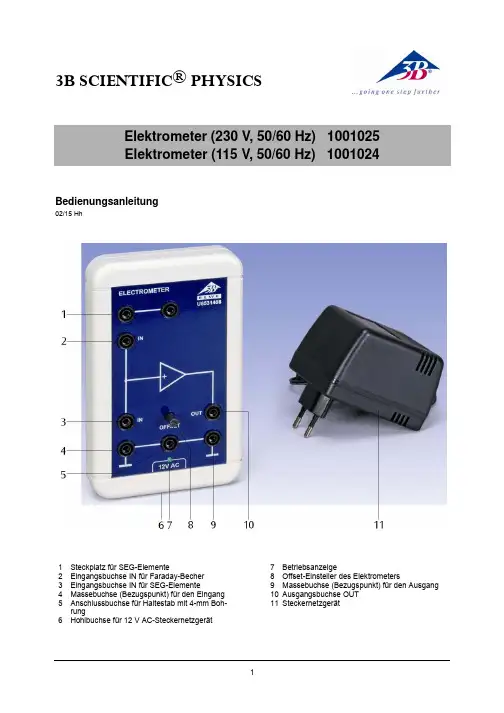
3B SCIENTIFIC ® PHYSICSElektrometer (230 V, 50/60 Hz) 1001025 Elektrometer (115 V, 50/60 Hz) 1001024Bedienungsanleitung02/15 Hh1 Steckplatz für SEG-Elemente2 Eingangsbuchse IN für Faraday-Becher3 Eingangsbuchse IN für SEG-Elemente4 Massebuchse (Bezugspunkt) für den Eingang 5Anschlussbuchse für Haltestab mit 4-mm Boh-rung6 Hohlbuchse für 12 V AC-Steckernetzgerät7 Betriebsanzeige 8 Offset-Einsteller des Elektrometers9 Massebuchse (Bezugspunkt) für den Ausgang 10 Ausgangsbuchse OUT 11 Steckernetzgerät1. SicherheitshinweiseElektrometer mit extrem hochohmigem, überspan-nungs-gefährdetem Spannungseingang:•Maximalwert der Eingangsspannung von ± 10 Vnicht überschreiten!Eine höhere Spannung ist nur dann zulässig, wennsicher gestellt ist, dass sie bei Berührung span-nungsführender Teile unverzögert auf den oben angegebenen Wert oder auf niedrigere Werte her-abgesetzt wird. Dies ist bei den im Text genannten Spannungsquellen gewährleistet.•Keine Fremdspannungen an die Ausgangs-buchse (10) anschließen! •Spannungsteilerschaltungen zur Messung von Spannungen über 10 V nur mit SEG-Kondensatoren bestücken, deren Spannungs-festigkeit für die anliegende Spannung aus-reicht!2. BeschreibungImpedanzwandler mit extrem hohem Eingangswi-derstand zur Messung kleinster Ladungen undkleinster Ströme.Geeignet zur quasistatischen Messung von Span-nungen bis ± 10 V, zur hochohmigen Messung von Spannungen über ± 10 V mit ohmschem Span-nungsteiler, zur quasistatischen Messung von Spannungen über ± 10 V mit kapazitivem Span-nungsteiler, zur Messung sehr kleiner Ströme mit hochohmigem Shuntwiderstand und zur Messungvon Ladungen.3. Technische DatenVerstärkung: 1,00 Eingangswiderstand: >1012ΩAusgangswiderstand: < 1 kΩEingangsstrom: < 10 pAEingangskapazität: < 50 pFMax. Ausgangsspannung: ± 10 VVersorgungsspannung: 12 V AC / 50-69 Hz/100 mAÜberspannungsfestigkeitfür nicht berührungs-gefährliche Spannungen: 1 kV (aus niederohmigenQuellen)10 kV (aus hochohmigenQuellen) Anschlüsse: 4-mm-Sicherheitsbuchsen Abmessungen: 110x170x30mm3 Masse: ca. 1 kg 4. Bedienung•12 V AC-Steckernetzgerät am Elektrometer anstecken, hiermit das Gerät einschalten. •Geeigneten Spannungsmesser mit Skalennull-punkt Mitte-Funktion an der Ausgangsbuchseanschließen, z.B. Analog-Multimeter AM50 (1003073), Vielfach-Messgerät ESCOLA2 (1006811), Vielfach-Messgerät ESCOLA10 (1006810).•Messbereich 10 V DC und Nullpunkt Mitte aus-wählen.•Eingangsbuchse IN (3) mit 19-mm-Brückenstecker gegen Massebuchse (4) kurz-schließen, oder•Faraday-Becher (1000972) in Eingangsbuchse(2) mit dem an der Erdungsbuchse (5) einge-steckten Haltestab mit 4-mm-Bohrung entladen(kurzschließen).•Bei bestehendem Kurzschluss den Offset der Ausgangsspannung an Buchse (10) minimie-ren.•Ausgewähltes Experiment zügig durchführen, bevor sich vagabundierende Ladungen auf demMesseingang ansammeln.•Vor Start eines neuen Experimentes wiederum Eingang kurzschließen und gegebenenfalls dieOffseteinstellung korrigieren.5. ExperimentierbeispielMessung von Ladungen in der ElektrostatikBenötigte Geräte:1 Elektrometer 1001024 / 10010251 Analog-Multimeter AM50 10030731 Faraday-Becher 10009721 Kondensator 10 nF aus 10068132 Reibstäbe 10027091 Exp.-Kabel, 75 cm 10028431 Haltestab mit 4-mm-Bohrung aus 10068131 Tuch, zum Reiben der Stäbe•Versuchsaufbau gemäß Fig. 1.•Den Faraday-Becher und den 10 nF-Kondensator in die hierfür vorgesehenen 4-mm-Buchsen einstecken.•Das Multimeter an der Ausgangsbuchse OUT(10) und der korrespondierenden Massebuchse(9) anschließen.•Am Multimeter den Messbereich 10 V DC wäh-len.3B Scientific GmbH ▪ Rudorffweg 8 ▪ 21031 Hamburg ▪ Deutschland ▪ Technische Änderungen vorbehalten •Das Experimentierkabel in die Anschlussbuch-se für den Haltestab (5) und in die 4-mm-Bohrung des Haltestabs einstecken.• Den Haltestab in der einen Hand halten undhiermit – ohne ihn los zu lassen – den Faraday-Becher entladen.• Mit der anderen Hand den Versuchskörper (z.B.den geriebenen Stab) zur Erfassung seiner ge-samten Ladung in den feldfreien Innenraum des Faraday-Bechers eintauchen und die Ladung an der Innenseite des Bechers …abstreifen“. • Die abgegebene Ladung gemäß der nachfol-genden Beziehungen und Gleichungen berech-nen.Zwischen der Ladung Q und der Spannung U eines Kondensators mit der Kapazität C besteht der Zu-sammenhang:U C Q =Wegen U OUT = U IN ist die Ausgangsspannung des Elektrometers ein Maß für die Ladung Q :C U Q OUT=•Mit der bekannten Kapazität C = 10 nF des Kondensators kann nunmehr die Ladung aus-gerechnet werden.Fig. 1Versuchsaufbau zur Messung von Ladungen in der Elektrostatik。
米高一体机说明书(新版)

目 录第一章产品的简介和应用 (2)1.1产品介绍 (2)1.2产品到货时确认 (2)1.3铭牌 (2)1.3.1铭牌举例 (3)1.3.2型号说明 (3)1.4安装场所和应用管理 (3)1.4.1安装场所 (3)1.4.2机房温度控制 (3)1.4.3作业时防止异物落入 (3)1.4.4安装方向和空间 (3)第二章器件连接及信号安装 (4)2.1主电路与电机接线 (4)2.2噪声滤波器的安装 (5)2.3一体机和电动机的接线距离原则 (6)2.4地线的连接 (6)2.5P G扩展卡端子及规格 (7)2.6控板端子及规格 (9)2.7外呼板(或内选显示)规格 (10)2.8内选板I/O规格..............................1 1 2.9桥顶板I/O规格..............................1 1 第三章参数一览表 (13)3.1操作器的使用 (13)3.2参数菜单结构/形式表 (15)3.3参数详细内容 (29)第四章一体机故障代码和解决方法 (42)4.1P03电梯故障记录代码表及处理方法 (42)4.2P01一体机驱动器故障信息及处理方法 (47)4.3P02驱动器当前故障对应的辅助代码及状态表 (51)4.4常见故障处理....................................5 3 第五章调试步骤 (57)5.1慢车的调试 (57)5.1.1运行条件及基本参数设定 (57)5.1.2异步电机自学习 (58)5.1.3同步电机自学习 (58)5.2快车的调试 (59)5.2.1井道开关的确认 (59)5.2.2井道参数自学习 (59)5.2.3平层及舒适感 (60)附录一电梯专用控制系统功能 (62)附录二外呼板地址设置……………………………………6 4第一章 产品的简介和应用1.1 产品简介我司研发的MICOLIFT一体机是集微机控制与变频驱动完美结合的新型产品,具有产品体积小布局精简可靠性高,人机界面友好操作简便,产品价格低廉,是电梯企业生产及改造的首选产品,当今电梯配套技术的主流。
科学实验室3B科学物理实验室气压测量器说明书

3B SCIENTIFIC ® PHYSICS1Istruzioni per l'uso09/15 ALF1 Valvola di immissione2 Capsula manometrica3 Valvola di scarico4 Tubo flessibileLa capsula manometrica serve per dimostrare il peso dell'aria e per determinarela densità dell'aria attraverso la compressione.È una capsula metallica con valvola da bicicletta per l'iniezione di aria e valvola di scarico.Dimensioni: 190 mm x 60 mm Ø Peso: ca. 100 gPer l'esperimento sono inoltre necessari i seguenti apparecchi:1 Pompa di bicicletta1 Bilancia elettronica 1003428 1 Cilindro graduato 500 ml 1 Tubo in vetro1 Tubicino di vetro, ad angolo retto2 Tappo di gomma con foro 1 Tappo di gomma senza foro 1 Base di supporto 1001044 1 Morsetto universale 1002833 1 Manicotto universale 1002830 1 Asta di supporto 1002938∙Determinare il peso m 1 della capsula manometrica con la bilancia prima dell'iniezione di aria.∙Riempire la capsula manometrica con aria con ca. 5 – 7 pompate utilizzando la pompa pneumatica.∙ Determinare con la bilancia il peso m 2 della capsula manometrica riempita.∙ La differenza m 2 – m 1 consente di dedurre il peso m della quantità di aria iniettata.∙ Per determinare il volume, realizzare la struttura di prova indicata nella fig. 1.∙A tale proposito, chiudere con un tappo in gomma un'estremità del tubo di vetro, nel quale è stato precedentemente inserito il tubicino di vetro ad angolo retto.∙Chiudere l'altro lato del tubo di vetro con il secondo tappo in gomma e collegare la capsula manometrica con il tubo flessibile.∙ Riempire completamente il tubo di vetro con acqua.∙ Chiudere il tubicino di vetro ad angolo retto con il tappo senza foro.∙Bloccare il tubo di vetro al supporto in posizione leggermente inclinata. Orientare l'altezza del bloccaggio, in modo che il tubicino di vetro sia rivolto verso il cilindro graduato sottostante. ∙Rimuovere i tappi dal tubicino di vetro e far fuoriuscire l'acqua in eccesso dal tubicino angolato, in modo che il livello dell'acqua raggiunga la curvatura. Rimuovere l'acqua dal cilindro graduato.3B Scientific GmbH ▪ Rudorffweg 8 ▪ 21031 Hamburg ▪ Deutschland ▪ Con riserva di modifiche tecniche © Copyright 2015 3B Scientific GmbH∙ Azionare la valvola di scarico lentamente fino ad eliminare l'aria dalla capsula manometrica.∙Raccogliere l'acqua spinta fuori dal tubo di vetro per mezzo dell'aria nel cilindro graduato e determinarne il volume.La quantità di acqua raccolta presenta lo stesso volume V dell'aria fuoriuscita dalla capsula manometrica. ∙Con i valori di misura ottenuti, calcolare la densità dell'aria secondo la formulaVm =ρ ∙ Ripetere l'esperimento più volte e calcolare il valore medio di ρ.∙Convertire il valore ρ così ottenuto per la densità dell'aria alle condizioni normali (0° C e 1013,3 mbar). A tale proposito, misurare la temperatura ambiente e la pressione atmosferica presenti al momento dell'esecuzione dell'esperimento.Fig. 1 Determinazione del volume dell'aria fuoriuscita。
Festo MVH-5 3E-3 8-B电压电控放大器说明书
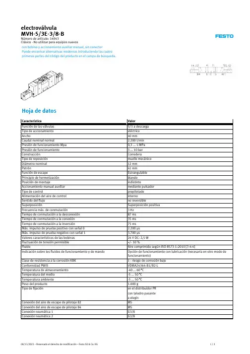
08/11/2023 – Reservado el derecho de modificación – Festo SE & Co. KG
1/2Biblioteka Característica
Conexión neumática 3 Conexión neumática 4 Conexión neumática 5 Indicación sobre el material Material de las juntas Material de la carcasa
Puede encontrar alternativas modernas introduciendo las cuatro primeras partes del código del producto en el campo de búsqueda.
Hoja de datos
Característica Función de las válvulas Tipo de accionamiento Ancho Caudal nominal normal Presión de funcionamiento Mpa Presión de funcionamiento Construcción Tipo de reposición Diámetro nominal Patrón Función de escape Principio de hermetización Posición de montaje Accionamiento manual auxiliar Tipo de control Alimentación del aire de control Sentido del flujo Superposición Frecuencia máx. de conmutación Tiempo de conmutación a la desconexión Tiempo de conmutación a la conexión Tiempo de conmutación a la inversión Máx. impulso de prueba positivo con señal 0 Máx. impulso de prueba negativo con señal 1 Valores característicos de las bobinas Fluctuación de tensión permisible Fluido Indicación sobre los fluidos de funcionamiento y de mando
康明斯柴油发动机技术参数说明书
-;HA?DIBasic technical dataNumber of cylinders.. ... ... ... ... ... ... ... ... ... ... ... ... ... ... ... ... .12 Cylinder arrangement ... ... ... ... ... ... ... ... ... ... ... ... ... ... 60° Vee Cycle. ... ... ... ... ... ... ... ... ... ... ... ..4 stroke, compression ignition Induction system... ... ... ... ... ... ... ... ... ... ... ... ... ...Turbocharged Compression ratio. ... ... ... ... ... ... ... ... ... ... ... ... ..13,6:1 nominal Bore... ... ... ... ... ... ... ... ... ... ... ... ... ... ... ... ... ... ... ... ... 160 mm Stroke ... ... ... ... ... ... ... ... ... ... ... ... ... ... ... ... ... ... ... ... 190 mm Cubic capacity... ... ... ... ... ... ... ... ... ... ... ... ... ... ... ..45.842 litres Direction of rotation... ... ... ... ...Anti-clockwise viewed on flywheel Firing order ... ... ... ... ... ... ...1A,6B,5A,2B,3A,4B,6A,1B,2A,5B.4A,3B Cylinder 1 furthest from flywheelCylinders designated ‘A’ are on the left side of the engine when viewed from the front (opposite end to flywheel)Total weight Electrounit (engine only)4012TAG1A/2A(dry).. ... ... ... ... ... ... ... ... ... ... ... ... ... ... 4400 kg 4012TAG1A/2A(wet) ... ... ... ... ... ... ... ... ... ... ... ... ... ... 4604 kg Overall dimensions ... ... ... ... ... ... ... ... ... ... ... ...Height 2118 mm .. ... ... ... ... ... ... ... ... ... ... ... ... ... ... ... ... ... ... ..Length 2731 mm .. ... ... ... ... ... ... ... ... ... ... ... ... ... ... ... ... ... ... ....Width 1723 mm Moment of inertia.. ... ... ... ... ... ... ... ... ... ... ... .Engine 9.73 kgm2 .. ... ... ... ... ... ... ... ... ... ... ... ... ... ... ... ... ... ..Flywheel 9.57 kgm2 Cyclic irregularity for engine/flywheel (Prime power):4012TAG1A ... 1500 rev/min ... ... ... ... ... ... ... ... ... ... ... ... 1,714 4012TAG2A ... 1500 rev/min ... ... ... ... ... ... ... ... ... ... ... ... 1,669RatingsSteady state speed stability at constant load. ... ... ... ... ...± 0,25% Electrical ratings are based on average alternator efficiency and are for guidance only (0,8 power factor being used). Operating pointEngine speed. ... ... ... ... ... ... ... ... ... ... ... ... ... ... ...1500 rev/min Static injection timing.. ... ... ... ... ... ... ... See engine number plate Cooling water exit temperature.. ... ... ... ... ... ... ... ... ... ... .<98 °C Fuel dataTo conform to BS2869 class A1, A2.PerformanceSound pressure level 1500 rev/min ... ... ... ... ... ... ...106/112 dBA Note:All data based on operation to ISO 3046/1, BS 5514 and DIN 6271 standard reference conditions.Test conditionsAir temperature... ... ... ... ... ... ... ... ... ... ... ... ... ... ... ... ... ...25 °C Barometric pressure... ... ... ... ... ... ... ... ... ... ... ... ... ... ...100 kPa Relative humidity ... ... ... ... ... ... ... ... ... ... ... ... ... ... ... ... (30)Air inlet restriction at maximum power (nominal)... ... ... ... 2,5 kPa Exhaust back pressure (nominal)... ... ... ... ... ... ... ... ... ... 3,0 kPa4000 Series 4012TAG1A 4012TAG2AGeneral installation 4012TAG1ADesignation Units50Hz 1500 rev/min60Hz 1800 rev/min ContinuousBaseloadPrimePowerStandbyMaximumContinuousBaseloadPrimePowerStandbyMaximumGross engine power kWb94211781292---Fan power kWm42---Net engine power kWm90011361250---BMEP gross bar1620,522,5---Combustion air flow m3/min7695105---Exhaust gas temperature max (after turbo)°C435460470---Exhaust gas flow max (after turbo)m3/min257---Boost pressure ratio-2,73,223,53---Mechanical efficiency%899192---Overall thermal efficiency%424342---Friction power and pumping losses kWm120---Mean piston speed m/s9,5---Engine coolant flow (min)l/s17---Typical Genset Electrical Output 0,8 pf 25 °C (100 kPa)kVA108013631500---kWe86410911200---Assumed alternator efficiency%96---Diesel Engine - ElectrounitGeneral installation 4012TAG2ANote:Not to be used for CHP design purposes. (Indicative figures only). Consult Perkins Engines Co. Ltd. Assumes complete combustion.Continuous Baseload rating Power available for continuous full load operation. Prime Power rating is available for unlimited hours per year with a variable load of which the average engine load factor is 80% of the published prime power rating, incorporation of a 10% overload for 1 hour in every 12 hours of operation which is permitted. Standby Power rating is for the supply of emergency power at variable load for the duration of the non-availability of the mains power supply. NO OVERLOAD capacity is available at this rating. Engines must not be allowed to have facilities for parallel operation with the mains supply. This rating should be applied only when reliable mains power is available. Should this not be the case then refer to Prime Power rating. A standby rated engine should be sized for an average load factor of 80% based on published standby rating for 500 operating hours per year. Standby ratings should never be applied except in true emergency power failure conditions.DesignationUnits 50Hz 1500 rev/min60Hz 1800 rev/minContinuous BaseloadPrime Power Standby Maximum Continuous BaseloadPrime Power Standby MaximumGross engine power kWb 103712961422---Fan power kWm 42---Net engine power kWm 99512541380---BMEP gross bar 18,122,624,8---Combustion air flowm 3/min 83,6106110---Exhaust gas temperature max (after turbo)°C 442472483---Exhaust gas flow max (after turbo)m 3/min 285---Boost pressure ratio -2,83,533,84---Mechanical efficiency %889292---Overall thermal efficiency%424241---Friction power and pumping losses kWm 120---Mean piston speed m/s 9,5---Engine coolant flowl/s 17---Typical Genset Electrical Output 0,8 pf 25 °C (100 kPa)kVA 119415051656---kWe 95512041325---Assumed alternator efficiency%96---Energy balanceNote:Not to be used for CHP design purposes. (Indicative figures only). Consult Perkins Engines Co Ltd. Assumes complete combustion. 4012TAG1A4012TAG2A Units1500 rev/min1800 rev/min ContinuousBaseloadPrimePowerStandbyMaximumContinuousBaseloadPrimePowerStandbyMaximumEnergy in fuel kWt223827703117---Energy in power output (gross) kWb94211781292---Energy to cooling fan kWm424242---Energy in power output (net)kWm90011361250---Energy to exhaust kWt680760924---Energy to coolant and oil kWt353434465---Energy to radiation kWt4495100---Energy to charge coolers kWt219303336---Units1500 rev/min1800 rev/min ContinuousBaseloadPrimePowerStandbyMaximumContinuousBaseloadPrimePowerStandbyMaximumEnergy in fuel kWt244430783477---Energy in power output (gross) kWb103712961422---Energy to cooling fan kWm424242---Energy in power output (net)kWm99512541380---Energy to exhaust kWt7508771013---Energy to coolant and oil kWt372464511---Energy to radiation kWt4995108---Energy to charge coolers kWt236346423---Cooling systemRecommended coolant: 50% inhibited ethylene glycol or 50% inhibited propylene glycol and 50% clean fresh water. For combined heat and power systems and where there is no likelihood of ambient temperatures below 10 °C then clean ‘soft’ water may be used, treated with 1% by volume of Perkins inhibitor in the cooling system. The inhibitor is available in bottles under Perkins Part No. 21825 735.Nominal jacket water pressure in crankcase. ... ... ... ... ... .1,7 bar The following is a guide based on ambient air conditions of 52 °C on a Perkins supplied radiator.Total coolant capacity:Electrounit (engine only) ... ... ... ... ... ... ... ... ... ... ... ... ... 73 litres ElectropaK (engine/radiator) . ... ... ... ... ... ... ... ... ... ... ..235 litres Pressure cap setting.. ... ... ... ... ... ... ... ... ... ... ... ... ... ...0,69 bar Fan. ... ... ... ... ... ... ... ... ... ... ... ... ... ... ...Incorporated in radiator Diameter ... ... ... ... ... ... ... ... ... ... ... ... ... ... ... 1524 mm pusher) Ambient cooling clearance (open ElectropaK Prime power) based on air temperature at fan 3 °C above ambient.4012TAG1A4012TAG2ACoolant pump speed andmethod of drive.. ... ... ... ... ... ... ... ... ... ... ... 1,4 x e rev/min gear Maximum static pressure head on pumpabove engine crank centre line.. ... ... ... ... ... ... ... ... ... ... ... ..7 m Maximum external permissible restrictionto coolant pump flow.. ... ... ... ... ... ... ... ... ... ... ... ... ... ... .20 kPa Thermostat operating range... ... ... ... ... ... ... ... ... ... ... ..71-85 °C Shutdown switch setting ... ... ... ... ... ... ... ... ... ... ... 101 °C rising Coolant immersion heater capacity ... ... ... ... ... ... ... ... ..4 kW x 2 *4012TAG2A **4012TAG1A Lubrication systemRecommended lubricating oil to conform with the specification of API CG4 15W/40 .Lubricating oil capacity:Sump maximum.. ... ... ... ... ... ... ... ... ... ... ... ... ... ... ... 159 litres Sump minimum... ... ... ... ... ... ... ... ... ... ... ... ... ... ... ... 136 litres Lubricating oil temperature maximum to bearings.. ... ... ... 105 °C Lubricating oil pressure:at 80 °C temperature to bearing gallery (minimum) ... ... 0,34 MPa 4012TAG1A4012TAG2A*Typical after 250 hoursSump drain plug tapping size.. ... ... ... ... ... ... ... ... ... ... ... ... ..G1 Oil pump speed and method of drive..1,4 x e rev/min, gear driven Oil pump flow 1500 rev/min. ... ... ... ... ... ... ... ... ... ...6,0 litres/sec Shutdown switch setting.. ... ... ... ... ... ... ... ... ... ...1,93 bar falling Normal operating anglesFore and aft. ... ... ... ... ... ... ... ... ... ... ... ... ... ... ... ... ... ... ... ...5°Side tilt ... ... ... ... ... ... ... ... ... ... ... ... ... ... ... ... ... ... ... ... (10)Maximum additional restriction (duct allowance) to cooling airflow (Prime power) and resultant minimum airflowAmbient clearance 50% glycol Duct allowancemm H20Min airflowm3/minrev/min rev/min rev/min 150018001500180015001800 52 °C52 °20-1872-Maximum additional restriction (duct allowance) to cooling airflow (Prime power) and resultant minimum airflowAmbient clearance 50% glycol Duct allowancemm H20Min airflowm3/minrev/min rev/min rev/min 150018001500180015001800 52 °C52 °20-1872-Jacket cooling water data Units1500rev/min1800rev/minCoolant flow 4012TAG1A/2A l/s17,0-Coolant exit temperature (max)°C98-Coolant entry temperature (min)°C70-Coolant entry temperature (max) *°C85-Coolant entry temperature (max)**°C88-Oil consumptionPrime PowerUnits1500rev/min1800rev/min After running-in*g/kWhr0,50-Oil flow rate from pump I/s6,0-Oil consumptionPrime PowerUnits1500rev/min1800rev/min After running-in*g/kWhr0,51-Oil flow rate from pump I/s6,0-Fuel systemRecommended fuel... ..To conform to BS2869 1998 Class A1, A2 Type of injection system ... ... ... ... ... ... ... ... ... ... ..Direct injection Fuel injection pump... ... ... ... ... ... ... ... ... .Combined unit injector Fuel injector... ... ... ... ... ... ... ... ... ... ... ... .Combined unit injector Fuel injector opening pressure.. ... ... ... ... ... ... ... ... ... ... .234 bar Fuel lift pump. ... ... ... ... ... ... ... ... ... ... ... ... ... .Tuthill TCH 1-089 Delivery/hour at 1500 rev/min... ... ... ... ... ... ... ... ... ... .1020 litres Heat retained in fuel to tank . ... ... ... ... ... ... ... ... ... ... ... ..9,5 kW Temperature of fuel at lift pump to be less than ... ... ... ... ... 58 °C Fuel lift pump pressure.. ... ... ... ... ... ... ... ... ... ... ... ... ... ..3,0 bar Fuel lift pump maximum suction head... ... ... ... ... ... ... ... ... 2,5 m Fuel lift pump maximum pressure head (see Installation Manual) Fuel filter spacing.. ... ... ... ... ... ... ... ... ... ... ... ... ... ..10 microns) Governor type... ... ... ... ... ... ... ... ... ... ... ... ... ... ... ... .Electronic Torque at the governor output shaft.. ... ... ... ... ... ... ... 1,631 kgm Static injection timing ... ... ... ... ... ... ... .See engine number plate Tolerance on fuel consumption. ... ... ... ... ... .To ISO 8528-1 1993 4012TAG1A4012TAG2A Induction systemMaximum air intake restriction of engine:Clean filter.. ... ... ... ... ... ... ... ... ... ... ... ... ... ... ... ... 127 mm H20 Dirty filter ... ... ... ... ... ... ... ... ... ... ... ... ... ... ... ... ... 380 mm H20 Air filter type... ... ... ... ... ... ... ... ... ... ... ... ... ...4998-00-00 MF&T Exhaust systemMaximum back pressure for total system.Exhaust outlet flange size.. ... ... ... ... ... ... .2 x 254 mm (table ‘D’) For recommended pipe sizes, refer to the Installation Manual. Electrical systemType... ... ... ... ... ... ... ... ... ... ... ... ... ... ... ... ... ...Insulated return Alternator ... ... ... ... ... ... ... ... ... ... 24 volts with integral regulator Alternator output. ... ... ...40 amps at a stabilised output 28 volts at20 °C ambient Starter motor.. ... ... ... ... ... ... ... ... ... ... ... ... ... ... ... ... .. 24 volts Starter motor power ... ... ... ... ... ... ... ... ... ... ... ... ... ... ...16,4 kW Number of teeth on flywheel... ... ... ... ... ... ... ... ... ... ... ... ... ..156 Number of teeth on starter motor... ... ... ... ... ... ... ... ... ... ... (12)Minimum cranking speed at (0 °C). ... ... ... ... ... ... ... .120 rev/min Pull-in current of each starter motor solenoid... ... ... ... ... ... ... ... ... ... ... ... ... ... ... ... ... ... .30 amps at 24 volts Hold-in current of each starter motor solenoid... ... ... ... ... ... ... ... ... ... ... ... ... ... ... ... ... ... ...9 amps at 24 volts Engine stop solenoid.. ... ... ... ... ... ... ... ... ... ... ... ... ... ...24 volts Pull-in current of stop solenoid... ... ... ... ... ... .60 amps at 24 volts Hold-in current of stop solenoid.. ... ... ... ... ... 1,1 amps at 24 voltsFuel consumption (gross)Designation g/kWh Litres/hr rev/min1500180015001800 At Standby Max power rating203-309-At Prime Power rating199-276-At Continuous Baseload rating197-218-At 75% of Prime Power rating195-203-At 50% of Prime Power rating194-134-At 25% of Prime power rating207-72-Fuel consumption (gross)Designation g/kWh Litres/hr rev/min1500180015001800 At Standby Max power rating206-345-At Prime Power rating201-306-At Continuous Baseload rating197-240-At 75% of Prime Power rating197-225-At 50% of Prime Power rating195-149-At 25% of Prime power rating207-79-Designation Units1500rev/min1800rev/min 4012TAG1A mmH20949-4012TAG2A mmH20612-Engine mountingPosition of centre of gravity (wet engine) forward from rearface of crankcase .. ... ... ... ... ... ... ... ... ... ... ... ... ... ... ...771 mm Engine vertical centre line above crankshaft centre line ... .38 mm Maximum additional load applied to flywheel due to all rotating components ... ... ... ... ... ... ... ... ... ... ... ... ... ... ... ... ... ... .850 kgStarting requirementsNotes:l Battery capacity is defined by the 20 hour rate at 0 °C.lThe oil specification should be for the minimum ambient temperature as the oil will not be warmed by the immersion heater.lBreakaway current is dependent on battery capacity available. Cables should be capable of handling the transient current which may be up to double the steady cranking current.TemperaturerangeRange Down to 0 °C(32 °F)Oil:Starter:Battery:Max breakaway current:Cranking current:Aids:Starter cable size:Maximum length:API CG4 15W/402 x 24V4 x 12 volts x 286 Ah 1600 amps 810 ampsNot necessary 120 mm 26mGA DrawingLoad acceptance (cold)4012TAG1A1500 rev/min4012TAG2A1500 rev/minAbove complies with requirements of Classifications 3 & 4 of ISO 8528-12 and G2 operating limits stated in ISO 8528-5.The above figures were obtained under test conditions as follows:Engine block temperature.. ... ... ... ... ... ..45 °C Alternator efficiency ... ... ... ... ... ... ... ... ... 96%Minimum ambient temperature.. ... ... ... ..10 °C Isochronous GoverningUnder Frequency Roll Off (UFRO) set to 1 Hz below rated frequency Typical alternator inertia. ... ... ... ... ... .50 Kgm 2All tests were conducted using an engine which was installed and serviced to Perkins Engines Company Limited recommendations.Initial load applicationwhen engine reaches rated speed(15 seconds max after engine starts to crank)2nd Load applicationImmediately after engine has recovered to rated speed(5 seconds after initial load application)Prime power%Load kWm/kWe Nett Transient frequency deviation%Frequency recovery time secondsPrime power%Load kWm/kWe Nett Transient frequency deviation%Frequency recovery time seconds63715/686< -10537422/405< -105Initial load applicationwhen engine reaches rated speed(15 seconds max after engine starts to crank)2nd Load applicationImmediately after engine has recovered to rated speed(5 seconds after initial load application)Prime power%Load kWm/kWe Nett Transient frequency deviation%Frequency recovery time secondsPrime power%Load kWm/kWe Nett Transient frequency deviation%Frequency recovery time seconds57715/686< -10543539/518< -105Noise levelsThe figures for total noise levels are typical for an engine running at Prime Power rating in a semi-reverberant environment and measured at a distance of one metre from the periphery of the engine.Octave analysisThe following histograms show an octave band analysis at the position of the maximum noise level.Total noise levelSound pressure level re: -20 x 10-6 paSpeed 1500 rev/min......Ambient noise level 84 dBA.Octave analysis performed at the position of maximum noise.4012TAG1A4012TAG2APOSITION 11500 rev/min 106 - dBA1800 rev/min ------- dBA1500 rev/min 106 - dBA1800 rev/min ------- dBAPOSITION 21500 rev/min 108 - dBA 1800 rev/min ------- dBA 1500 rev/min 108 - dBA 1800 rev/min ------- dBA POSITION 3 1500 rev/min 111 - dBA 1800 rev/min ------- dBA 1500 rev/min 111 - dBA 1800 rev/min ------- dBA POSITION 4 1500 rev/min 111 - dBA 1800 rev/min ------- dBA 1500 rev/min 111 - dBA 1800 rev/min ------- dBA 4012TAG1A 4012TAG2A 4012TAG1A 4012TAG2A 4012TAG1A 4012TAG2A4012TAG1A4012TAG2A POSITION 71500 rev/min 108 - dBA 1800 rev/min ------- dBA 1500 rev/min 108 - dBA 1800 rev/min ------- dBA POSITION 6 1500 rev/min 112 - dBA 1800 rev/min ------- dBA 1500 rev/min 112 - dBA 1800 rev/min ------- dBA POSITION 5 1500 rev/min 112 - dBA 1800 rev/min ------- dBA 1500 rev/min 112 - dBA 1800 rev/min ------- dBA 4012TAG14012TAG24012TAG14012TAG24012TAG1A4012TAG2AFR4012TAG1A4012TAG2AThe information given on technical data sheets are for standard ratings only. For ratings other than shown contact Perkins Engines Company Limited, Stafford.Notes-;HA?DI All information in the document is substantially correct at the time of printing but may be subsequently altered by the company.Distributed by 4000 Series4012TAG1A 4012TAG2A P u bl i c a t i o n N o . T S L 4253, I s s u e 3, J a n u a r y 2003. P r i n t e d i n E n g l a n d . © P e r k i n s E n g i n e s C o m p a n y L i m i t e d .Perkins Engines Company Limited Stafford ST16 3UB United Kingdom Telephone +44 (0)1785 223141Fax +44 (0)1785 。
3B Scientific P50 系统的更新套件说明书
KIT DE ACTUALIZACIÓN DEL SISTEMA DE INFUSIÓN P50 (1021421)MANUAL DEL USUARIO2KIT DE ACTUALIZACIÓN DEL SISTEMA DE INFUSIÓN P50 (1021421) ¿Tiene más preguntas?Tel.: +49 (0)40 739 66-0CONTENIDO DEL KIT DE ACTUALIZACIÓN DEL SISTEMA DE INFUSIÓN P50• 1 soporte • 1 botella de infusión con una pinza de cierre para tubo y un conector en Y para tubo • 1 conector transparente para tubo • Sistema de 3 tubos de infusión (como piezas de repuesto)• 1 botella de concentrado de sangre artificial 3B Scientific® (250 ml)Este kit de actualización le permitirá mejorar el brazo de inyección i.v. 3B Scientific® (P50).Mejora del sistema de infusión:• El sistema de infusión del brazo de inyección i.v. resulta más fácil de instalar.• Ahora el sistema de infusión es un sistema cerrado que reduce el riesgo de fuga mientras se utiliza.Mejora de la sangre artificial:• El color de la sangre es más realista. • Las manchas provocadas por la nueva sangre artificial se eliminan al lavar a 40 °C.Mayor eficiencia:• La nueva botella de 250 ml permite realizar 10 aplicaciones, es decir, 6 más que la botella anterior.Sistema de infusión anteriorEste kit de actualización del sistema de infusión sustituye al sistema P50 anterior y al soporte metálico. Cómo instalar el kit de actualización de un modo sencilloINSTRUCCIONES DE USO1. Retire y deseche el sistema de infusión anterior, tal y como se observa en la imagen previa.2. Acople el conector transparente al tubo más corto.3. Coloque la pinza de cierre en el tubo más largo.4. Acople el conector en Y al tubo abierto en la parte inferior de la botella de infusión.5. Retire y deseche el soporte metálico anterior y sustitúyalo por uno nuevo.Llenado de la botella de infusión con sangre 1. Asegúrese de que la pinza de cierre del tubo de ventilación de la botella de infusión está cerrada.2. Llene la botella de infusión hasta la línea roja con el concentrado de sangre artificial. 3. A continuación, llene la botella de infusión hasta la línea azul con agua.4. Cierre la botella y agítela con suavidad para obtener una solución homogénea.341234KIT DE ACTUALIZACIÓN DEL SISTEMA DE INFUSIÓN P50 (1021421) ¿Tiene más preguntas?Tel.: +49 (0)40 739 66-0Instalación del sistema de infusión 1. Sujete el gancho en la parte central del soporte. 2. Cuelgue el brazo de inyección en el gancho con el tornillo de rosca del brazo.3. Conecte el tubo de inyección más corto a la botella de infusión. 4. Asegúrese de que la pinza de cierre del tubo más largo está cerrada.5. S ujete la botella de infusión boca abajo con la pinza de retención; para ello, agarre la botella por los laterales e introduzca el tapón de sellado en la pinza de retención gris del soporte. 6. I ntroduzca el tubo más largo en el vaso de plástico y deje que la sangre fluya por el tubo hacia el vaso durante unos segundos para eliminar las burbujas. 7. U na vez que haya comprobado que todas las conexiones se han establecido correctamente y que el tubo más largo está dentro del vaso de plástico, abra la pinza de cierre del tubo de ventilación de la botella de infusión y la pinza de cierre del tubo más largo. 8. E l sistema se llenará y la sangre comenzará a salir por el tubo más largo y se verterá en el vaso de plástico. Deje que la sangre fluya y salga por el tubo hasta que no vea más burbujas.9. C ierre la pinza del tubo más largo y conéctelo a una de las ramas del conector en Y de la botella de infusión. 10. Y a puede empezar con la punción de las venas periféricas.3579105 Después de usar el brazo de inyección Siga los pasos que se indican a continuación para eliminar la sangre artificial después de utilizar el brazo de inyección:1. A segúrese de que la pinza de cierre del tubo de ventilación de la botella de infusión está cerrada. 2. A segúrese de que la pinza de cierre del tubo más largo está cerrada.3. D esconecte el tubo más largo del conector en Y.4. R etire la botella de infusión de la pinza de retención del soporte y gírela para ponerla en posición vertical.5. D esconecte el tubo más corto del conector de la botella; para ello, desenrosque el conector con suavidad. 6. C oloque los extremos de los tubos en un recipiente o cubeta para eliminar los restos de sangre del sistema de tubos.Si no va a utilizar el brazo de inyección durante un periodo largo, se recomienda enjuagar todo el sistema de tubos para que no se asienten los restos de tinte en este.Llene con agua la botella de infusión y repita todos los pasos de instalación para limpiar el sistema. 2a 2b 2c1. P ara cambiar el sistema de tubos, en primer lugar deberá retirar la piel. Primero, retire el conector transparente del tubo más corto y quite la pinza de cierre del tubo más largo.2. Desenrosque el tornillo de rosca y abra las dos piezas de los tapones de sellado del brazo.CAMBIO DE LA PIEL Y DEL SISTEMA DE TUBOS Cómo cambiar el sistema de tubos6KIT DE ACTUALIZACIÓN DEL SISTEMA DE INFUSIÓN P50 (1021421) ¿Tiene más preguntas?Tel.: +49 (0)40 739 66-0345Cómo volver a poner la piel TENGA EN CUENTA LO SIGUIENTE:1. P ara apartar la piel nueva de la estructura de mano y brazo, ponga polvos de talco en la piel y distribúyalos moviendo la piel hacia adelante y hacia atrás.2. R etire la piel de la estructura de mano y brazo y vuelva a introducir el tubo por el orificio y las placas de protección. El borde de la piel debe estar cerrado entre los dos placas de protección. Apriete el tornillo de rosca y sustituya los tapones de sellado de los tubos.3. N o se olvide de volver a acoplar el conector transparente del tubo del brazo más corto y de volver a instalar la pinza de cierre del tubo más largo.• L a piel y el sistema de tubos del brazo de inyección son susceptibles al desgaste y a las roturas provocadas por el uso. Suministramos la piel y el sistema de tubos como piezas de repuesto.• C omo el brazo de inyección es un modelo anatómico, se han representado en la piel algunas venas, no aptas para punción, además de las venas que sí se pueden punzar.• L a sangre artificial puede provocar manchas. Pero no se preocupe, las manchas provocadas por la sangre artificial 3B Scientific® se eliminan al lavar a 40 °C.• L as cánulas venosas permanentes pueden dañar el material de la piel y del sistema de tubos. Utilice únicamente cánulas de inyección del tamaño recomendado (del calibre 20 o 21) y cambie la piel o el sistema de tubos cuando se aprecien daños en la piel. 3. Enrolle la piel de la estructura de brazo comenzando por la parte superior del brazo.4. Suelte las tiras de velcro y extraiga el sistema de tubos de la estructura de brazo.5. Instale el sistema de tubos nuevo en las ranuras provistas y vuelva a sujetarlo con las tiras de velcro.7CONTACTO CON 3B SCIENTIFIC NÚMEROS DE PRODUCTO DE LAS PIEZAS DE REPUESTO Cuando se ponga en contacto con el servicio de asistencia técnica, tenga a mano el producto de simulación y el manual.A worldwide group of companies3B Scientific GmbHCustomer Service MedicalRudorffweg 8 • 21031 Hamburg • GermanyPhone: + 49 (0)40-73966-0 • Fax: + 49 (0)40-73966-100 •*********************。