西门子电话GIGASET 2025C 说明书
西门子操作手册

目录1 安全信息 (1)术语定义 (1)前言 (1)2定位器的供货范围 (2)3组装…………………………………………………………………概述…………………………………………………………………定位器在潮湿环境中的使用……………………………………定位器在易受到强加速作用力或震动场合的使用……………直行程执行机构的连接附件………………………………………组装顺序……………………………………………………………角行程执行机构的连接附件………………………………………组装顺序………………………………………………………………4可选附件的安装……………………………………………………5电气连接……………………………………………………………6气动连接……………………………………………………………注入仪表空气开关………………………………………………..限流器………………………………………………………………7调试(见散页“操作—简要说明”)………………………………直行程执行机构调试准备…………………………………………直行程执行机构的自动初始化…………………………………直行程执行机构的手动初始化…………………………………角行程执行机构调试准备…………………………………………角行程执行机构的自动初始化…………………………………角行程执行机构的手动初始化…………………………………故障校正……………………………………阀门定位器的简明操作指南………………..附录一………………………………………………………………………附录二………………………………………………………………………1 安全信息1.2 前言本操作说明描述了定位器组装、连接、调试的基本步骤,不能取代SIPART PS2电气阀门定位器的操作手册,操作手册中包含了组装、功能、操作的详细信息。
无危险使用关于安全方面,定位器出厂时已达到完美状态,如果要保持此状态,用户必须要遵守本操作说明中安全提示。
西门子Load Feeder AS-Interface 2.0说明说明书

Applications & Tools Answers for industry. Cover SheetIndustrial controls SIRIUS InnovationsLoad Feeder with AS-Interface Connection to the Control and Integration into STEP 7 Application description June 20102Load Feeder with AS-Interface2.0, Article ID: 41141976, Doc-ID: CE-FE-III-011-V20-ENC o p y r i g h t S i e m e n s A G 2010 A l l r i g h t s r e s e r v e dIndustry Automation and Drives Technologies Service & Support PortalThis document is available via the Siemens AG Industry Automation and Drives Technologies Internet service portal. The document can be downloaded directly via the following link:/WW/view/en/41141976If you have any questions on this article, please contact us at the following e-mail address:*************************************Load Feeder with AS-Interface2.0, Article ID: 41141976, Doc-ID: CE-FE-III-011-V20-EN 3C o p y r i g h t S i e m e n s A G 2010 A l l r i g h t s r e s e r v e dsSIRIUS InnovationsLoad Feeder with AS-InterfaceConnection to the Control and Integration into STEP 7Preface 1Application description2Structure and installation of the application3Configuration4Further reading5History6Guarantee and liability4Load Feeder with AS-Interface2.0, Article ID: 41141976, Doc-ID: CE-FE-III-011-V20-ENC o p y r i g h t S i e m e n s A G 2010 A l l r i g h t s r e s e r v e dGuarantee and liabilityNoteApplication examples are non-binding and do not claim to be complete with regard to configuration, equipment or to any contingency. The applicationexamples are not customer-specific solutions. They are merely intended to assist in dealing with typical problems. You are solely responsible for the correctoperation of the described products. These application examples do not relieve you of your responsibility for safe usage, installation, operation and maintenance. By using these application examples, you accept that we are not liable for any damage beyond the liability described. We reserve the right to make changes to these application examples at any time, without prior notice. If the suggestions in this application example deviate from other Siemens publications (e.g. catalogs), the contents of the other document have priority.We assume no liability for any of the information contained in this document. We are not liable for any damage caused by the use of the examples, information, programs, configuration and performance data, etc. described in this application example, independent of the legal ground upon which this is based, unless we are imperatively liable according to the product liability law, e.g. due to cases ofpremeditation, an act of gross negligence, injury to life, body or health, or unless the quality of a product has been guaranteed, or due to fraudulent concealment of a defect or serious breach of contract. Damages due to serious breach of contract are, however, restricted to prevalent and foreseeable contractual damages,inasmuch as there is no premeditation or gross negligence nor imperative liability due to injury to life, body or health. This does not constitute a change in the burden of proof to your disadvantage.Propagation or reproduction of these application examples or parts thereof is not permitted unless expressly allowed by Siemens Industry Sector.Table of contentsLoad Feeder with AS-Interface2.0, Article ID: 41141976, Doc-ID: CE-FE-III-011-V20-EN 5C o p y r i g h t S i e m e n s A G 2010 A l l r i g h t s r e s e r v e dTable of contentsGuarantee and liability ................................................................................................4 1 Preface................................................................................................................6 1.1 Objective of the application..................................................................6 2Application description (7)2.1 Content.................................................................................................7 2.2 Structure...............................................................................................8 2.2.1 Overview ..............................................................................................8 2.2.2 Requirements.......................................................................................8 2.2.3 Advantages of this solution..................................................................9 2.2.4 Required hardware and software components....................................9 2.2.5 Alternative solutions...........................................................................10 3Structure and installation of the application (11)3.1 Content...............................................................................................11 3.2 Installation and commissioning..........................................................11 3.3 Installation of the hardware and software..........................................11 4Configuration...................................................................................................12 4.1Configuration of the station................................................................12 5Further reading................................................................................................15 5.1 Literature references..........................................................................15 5.2Internet link information (15)6 History (16)Preface1.1 Objective of the application6Load Feeder with AS-Interface2.0, Article ID: 41141976, Doc-ID: CE-FE-III-011-V20-ENC o p y r i g h t S i e m e n s A G 2010 A l l r i g h t s r e s e r v e dPreface11.1Objective of the applicationThe use of function modules with AS-Interface facilitates use in decentralized solutions. This ensures connection to the TIA environment.This application shows the structure of load feeders using conveyors in a conveyor system and their integration into STEP 7.Core content of this applicationThe following core issues are discussed: •Connection to a control via AS-Interface Basic knowledge of this topic is required.Structure of the documentThe documentation of this application is divided into the following main parts.Table 1-1PartDescriptionApplication descriptionThis chapter gives you an overview. The required standard hardware and standard software components are introduced, as well as the specially programmed application software.Structure and installation of the applicationThis section provides a step-by-stepexplanation of the structure and installation of the application.ConfigurationThis chapter describes the softwareconfiguration steps which are necessary for the configuration of the hardware components.Further readingThis chapter provides further information, e.g. literature references.Application description2.1 ContentLoad Feeder with AS-Interface2.0, Article ID: 41141976, Doc-ID: CE-FE-III-011-V20-EN 7C o p y r i g h t S i e m e n s A G 2010 A l l r i g h t s r e s e r v e dApplication description22.1 ContentThis application example describes the connection of a conveyor to a load feeder with function module for AS-Interface. When loading and unloading machine tools, individual conveyors can easily be combined in groups.The following is an example for the connection of load feeders to a control via AS-Interface.Application description 2.2 Structure8Load Feeder with AS-Interface2.0, Article ID: 41141976, Doc-ID: CE-FE-III-011-V20-ENC o p y r i g h t S i e m e n s A G 2010 A l l r i g h t s r e s e r v e d2.2 Structure2.2.1OverviewFor the control of conveyors positioned at a distance from one another within the system, the load feeders are supplied via a power bus. The diagram below shows an example of a conveyor with a turntable. Connection to the control is implemented via AS-Interface.Figure 2-1 Connection of the load feeder via AS-Interface2.2.2 RequirementsThe main energy supply (400 V AC) is ensured via a power bus. A line must be used which is protected against short-circuits and overload (e.g. within the control cabinet).The load feeders need a separate 24 V DC supply.Installation of the DP/AS-i Link depends on the extent of the AS-Interface bus.Application description2.2 StructureLoad Feeder with AS-Interface2.0, Article ID: 41141976, Doc-ID: CE-FE-III-011-V20-EN 9C o p y r i g h t S i e m e n s A G 2010 A l l r i g h t s r e s e r v e d2.2.3 Advantages of this solutionWith a distributed configuration, AS-Interface is a convenient solution for controlling the drives. The load feeders can be combined to groups.2.2.4 Required hardware and software componentsThe following tables show the minimum configuration of the hardware and software components.Table 2-2 Hardware componentsComponentQuantity MLFB / order number Note 24 V DC power supply 16EP1 33..Depends on the required outputSIMATIC S7 300 CPU CPU313C-2 DP 1 6ES7313-6CF03-0AB0 — AS-i Master 1 6GK1415-2BA10 — AS-i power supply 1 3RX9502-0BA00 — Components for direct starters Motor starter protector2 3RV2011-1AA10 — Link module23RA1921-1DA00—Contactor 2 3RT2015-1BB41-0CC0 —Function module forAS-Interface, direct start 2 3RA2712-1AA00 —Components for reversing startersMotor starter protector 1 3RV2011-1AA10 — Link module13RA1921-1DA00—Installation kit for reversing combination1 3RA2913-2AA1 • Wiringmodules top and bottom • Mechanicalinterlocking • Twoconnection clips Contactor 2 3RT2015-1BB42-0CC0 — Function module forAS-Interface, reversing start1 3RA2712-1BA00 —Table 2-3 Software componentsComponentQuantity MLFB / order number NoteSIMATIC STEP 716ES7810-4CC08-0JA5—Application description 2.2 Structure10Load Feeder with AS-Interface2.0, Article ID: 41141976, Doc-ID: CE-FE-III-011-V20-ENC o p y r i g h t S i e m e n s A G 2010 A l l r i g h t s r e s e r v e d2.2.5 Alternative solutionsAn AS-i Master CP - CP 243-2 (S7-200) or CP 343-2 (S7-300) - can be used instead of a DP/AS-i Link.An IE/AS-i Link must be used for the connection of the AS-Interface to the PROFINET.The configuration of the application with a load feeder is the same for the alternative solutions.Structure and installation of the application3.1 ContentC o p y r i g h t S i e m e n s A G 2010 A l l r i g h t s r e s e r v e dStructure and installation of the application33.1 ContentThis section provides a step-by-step explanation of the structure and installation of the application.3.2 Installation and commissioningThis chapter describes the hardware and software that must be installed, as well as the commissioning steps for the example.3.3 Installation of the hardware and softwareThis chapter describes the hardware and software components that must be installed. The descriptions, manuals and delivery information supplied with the respective product must be observed under all circumstances.Installation of the hardwareThe hardware components can be found in chapter 2.2.4.The structure of the hardware components is provided in chapter 2.2.1. Standard lines can be used for the connection to the AS-i modules.Note The installation guidelines for all components must always be observed.Installation of the softwareTable 3-4No. ActionNote1.SIMATIC STEP 7 installationPlease observe the instructions provided by the installation programConfiguration4.1 Configuration of the stationC o p y r i g h t S i e m e n s A G 2010 A l l r i g h t s r e s e r v e dConfiguration4In order to integrate the load feeder into the control, an AS-i Master (here: AS-Interface DP/AS-i Link Advanced) must be assigned to the CPU.4.1 Configuration of the stationAs a first step, an AS-I Master must be connected to the DP master system in HW Config.Figure 4-2Configuration4.1 Configuration of the stationC o p y r i g h t S i e m e n s A G 2010 A l l r i g h t s r e s e r v e dA slave must then be inserted into the AS-i Master The individual load feeders can be configured as slaves with the AS-i Master.Figure 4-3Configuration4.1 Configuration of the stationC o p y r i g h t S i e m e n s A G 2010 A l l r i g h t s r e s e r v e dAn AS-Interface A/B slave profile must be selected for the load feeder. The AS-i profile must be set as follows within the "Object properties" dialog:Table 4-5 IO code7 ID code A ID1 code 7 ID2 code7With this configuration, the I/O address can be changed for each load feeder.Figure 4-4As an alternative, the slave parameterization with the AS-i Master can be omitted.Further readingC o p y r i g h t S i e m e n s A G 2010 A l l r i g h t s r e s e r v e dFurther reading55.1Literature referencesThis list is not complete. It only provides a selection of possible further reading.Table 5-6Topic Title/1/STEP 7Automatisieren mit STEP 7 in AWL und SCL Hans BergerPublicis MCD Verlag ISBN 3-89578-113-45.2 Internet link informationThis list is not complete. It only provides a selection of possible further reading.Table 5-7Topic Title\1\ Link to the document/WW/view/en/41141976\2\ Siemens A&DCustomer Support \3\ AS-Interface system manual /WW/view/com/26250840 \4\Catalog News LV 1 N - SIRIUS Innovations/industrial-controls/catalogsHistoryC o p y r i g h t S i e m e n s A G 2010 A l l r i g h t s r e s e r v e dHistory6Table 6-8 History VersionDateChangeV1.0 11.01.2010 First issueV2.0 28.06.2010Update of the components for direct starters and reversing starters order numbers。
西门子家居电子产品说明书
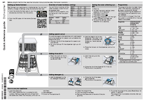
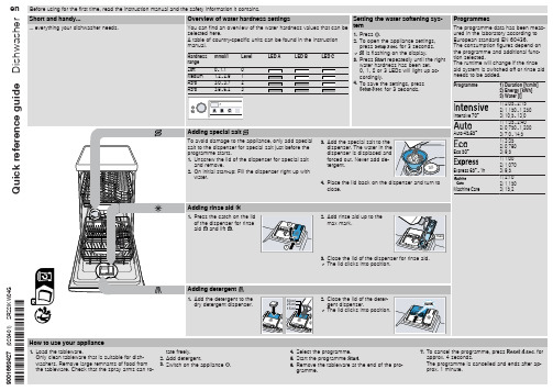
Setting the water softening sys-
H02
tem
H03
1. Press .
H04
2. To open the basic settings, press
H05
for 3 seconds.
H06
a The display shows Hxx.
H07
a The display shows .
gether and lift
1
the coarse filter
out .
Cleaning spray arms
1. Unscrew the upper spray arm and
2
pull down to remove .
1
2
5. Clean the filter elements under running water.
Cause and troubleshooting
Supply hose is kinked. ▶ Install the supply hose without kinks.
Water tap is turned off. ▶ Turn on the water tap.
Water tap is jammed or furred up. ▶ Turn on the water tap.
en Before using for the first time, read the instruction manual and the safety information it contains.
Quick reference guide Dishwasher
Setting up Home Connect
西门子 说明书
SIMATICS7/HMISIMATIC Automation Tool SDK V3.1 SP2 Product informationProduct InformationSiemens AG Division Digital Factory A5E45252984-AAⓅ 10/2018 Subject to changeCopyright © Siemens AG 2018.All rights reservedLegal informationWarning notice systemThis manual contains notices you have to observe in order to ensure your personal safety, as well as to preventdamage to property. The notices referring to your personal safety are highlighted in the manual by a safety alertsymbol, notices referring only to property damage have no safety alert symbol. These notices shown below aregraded according to the degree of danger.indicates that death or severe personal injury will result if proper precautions are not taken.WARNINGindicates that death or severe personal injury may result if proper precautions are not taken.CAUTIONindicates that minor personal injury can result if proper precautions are not taken.NOTICEindicates that property damage can result if proper precautions are not taken.If more than one degree of danger is present, the warning notice representing the highest degree of danger willbe used. A notice warning of injury to persons with a safety alert symbol may also include a warning relating toproperty damage.Qualified PersonnelThe product/system described in this documentation may be operated only by personnel qualified for the specifictask in accordance with the relevant documentation, in particular its warning notices and safety instructions.Qualified personnel are those who, based on their training and experience, are capable of identifying risks andavoiding potential hazards when working with these products/systems.Proper use of Siemens productsNote the following:WARNINGSiemens products may only be used for the applications described in the catalog and in the relevant technicaldocumentation. If products and components from other manufacturers are used, these must be recommendedor approved by Siemens. Proper transport, storage, installation, assembly, commissioning, operation andmaintenance are required to ensure that the products operate safely and without any problems. The permissibleambient conditions must be complied with. The information in the relevant documentation must be observed. TrademarksAll names identified by ® are registered trademarks of Siemens AG. The remaining trademarks in this publicationmay be trademarks whose use by third parties for their own purposes could violate the rights of the owner. Disclaimer of LiabilityWe have reviewed the contents of this publication to ensure consistency with the hardware and softwaredescribed. Since variance cannot be precluded entirely, we cannot guarantee full consistency. However, theinformation in this publication is reviewed regularly and any necessary corrections are included in subsequenteditions.Table of contents1 Components of the SIMATIC Automation Tool SDK (4)Components of the SIMATIC Automation Tool SDK 1 The SIMATIC Automation Tool Software Development Kit (SDK) consists of the followingcomponents:●Setup application for installing the SDK●SIMATIC Automation Tool Application Programming Interface (API): a set of .NETinterfaces, classes, and methods to perform network and device operations● A Windows installer package to use in creating a setup for your users. Your users caninstall your custom application from the setup you create. The installer provides for asilent installation of the API and S7 communication components with no licenserequirement.●Product Information●Installation Notes●User Guide●Totally Integrated Automation UPDATER (TIA Software Updater) for performing futureupdates to the SDK。
西门子定位器说明书
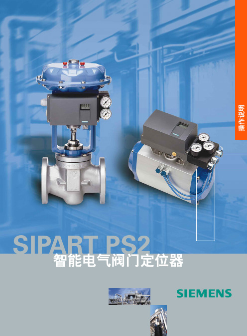
1特殊的螺丝8滑动夹紧装置的调节轮9变送比率选择器10隔离盖板附录29基本部件的电路连接图9非防爆二线制连接图10防爆二线制连接图11非防爆二线制连接阀门定位器二进制输入1hart通讯420ma只对危险区1级或2级非危险区域带认证的相关设备或安全栅阀门定位器二进制输入1420ma420ma阀门定位器二进制输入1附录30图12非防爆34线制连接图13防爆2线制连接1835v阀门定位器二进制输入10420ma只用于3线制危险1区或2区非危险区带认证的相关设备或安全栅420ma阀门定位器二进制输入1手操器附录31图14防爆34线连接可选件的电气连接图15非防爆jy模块图16防爆jy模块危险1区或2区非危险区带认证的相关设备或安全栅1830v阀门定位器二进制输入1手操器0420ma只用于3线连接jy模块6dr40048j危险1区或2区非危险区带认证的相关设备或安全栅jy模块6dr40046j附录32图17非防爆报警模块图18防爆报警模块报警模块6dr40048a报警限位a1限位a2报警模块6dr40046a报警限位a1限位a2带认证的相关设备或安全栅危险1区或2区非危险区附录33图19非防爆sia模块图20防爆sia模块sia模块6dr40048g报警限位a1限位a2sia模块6dr40046g报警限位a1限位a2带认证的相关设备或安全栅危险1区或2区非危险区附录34sipartps26dr5xxxxx注意
西门子电子家居设备指南说明书
7. To cancel the programme, press
for
approx. 4 seconds.
The programme is cancelled and ends after ap-
prox. 1 minute.
Cleaning filters
1. After each wash check the filters for
2. Pull up the lower spray arm to remove.
3. Check the outlet nozzles on the spray arms for blockages under running water and remove any foreign bodies.
Siphon connection is still sealed. ▶ Check the connection to the siphon and open if necessary.
Cover of the wastewater pump is loose. ▶ Secure the cover of the Wastewater pump so it clicks into
gether and lift
1
the coarse filter
out .
Cleaning spray arms
1. Unscrew the upper spray arms and
2
pull down to remove .
1 2
Clean wastewater pump
1. Disconnect the appliance from the power supply. 2. Remove the filter system. 3. Scoop out any water. 4. Prise off the pump cover using a
西门子 NXGPro+ 控制系统手册_操作手册说明书
3.4
单元通讯的协议 ............................................................................................................ 36
3.5
NXGpro+ 高级安全 .......................................................................................................37
3.2
功率拓扑 ......................................................................................................................34
3.3
控制系统概述 ...............................................................................................................35
NXGPro+ 控制系统手册
NXGPro+ 控制系统手册
操作手册
AC
A5E50491925J
安全性信息
1
安全注意事项
2
控制系统简介
3
NXGPro+ 控制系统简介
4
硬件用户界面说明
5
参数配置/地址
6
运行控制系统
7
高级的操作功能
8
软件用户界面
9
运行软件
10
故障和报警检修
11
西门子TM Timer DIDQ 10x24V用户手册说明书

1 000 m; Depending on sensor, cable quality and rate of change 600 m; Depending on sensor, cable quality and rate of change
General information Product type designation usable BaseUnits Product function ● I&M data
Supply voltage Load voltage L+ ● Rated value (DC) ● permissible range, lower limit (DC) ● permissible range, upper limit (DC) ● Reverse polarity protection
Digital outputs Type of digital output Number of digital outputs Current-sinking Current-sourcing Digital outputs, parameterizable Short-circuit protection ● Response threshold, typ. Limitation of inductive shutdown voltage to Digital output functions, parameterizable ● Digital output with time stamp — Number, max. ● PWM output — Number, max. ● Digital output with oversampling — Number, max. Switching capacity of the outputs ● with resistive load, max. ● on lamp load, max. Load resistance range ● lower limit ● upper limit Output voltage ● Type of output voltage ● for signal "0", max. ● for signal "1", min. Output current ● for signal "1" rated value ● for signal "1" permissible range, max. ● for signal "1" minimum load current ● for signal "0" residual current, max. Output delay with resistive load ● "0" to "1", max. ● "1" to "0", max. Switching frequency ● with resistive load, max. ● on lamp load, max. Total current of the outputs ● Current per module, max.