
最新CISCO路由器DHCP配置详解_图文.ppt
cisco RV 120W 路由器配置成VLAN交换机

思科RV 120W 路由器配置成小型交換機1、使用網線把電腦和交換機LAN1或其他LAN口相連接。
2、打開IE流覽器輸入192.168.1.1(新交換機默認IP)。
3、在下圖中輸用戶名:admin,密碼為admin或為空(默認)點擊Log In 登錄。
用戶登錄4、思科RV 120W設置界面如下:5、設置路由訪問IP和關閉DHCP:設置路由訪問IP選擇DHCP是否關閉6、關閉無線網絡,進入以下界面。
無線開啟狀態顯示7、選擇要更改的無線網AP,點擊Edit,進入設置無線網絡是否開啟界面:8、重設用戶名和密碼:9、新建VLAN勾選為開啟,取消勾選為關閉修改用戶名稱修改密碼保存已建好VLAN點Add 添加VLAN10、點Add 添加VLAN輸入VALN描述名稱ID編號名稱保存11、輸入VALN描述名稱和ID編號(根據實際情況自己設定),點Save保存。
12、設置VLAN IP地址和子網掩码13、選擇要編輯的VLAN號,點擊Edit。
14、修改后關閉DHCP點擊保存。
15、VLAN端口分配:已設定VLAN IP地址勾選要編輯的VLAN ID點擊Edit修改VLAN IP地址和子網掩码修改VLANIP地址和子選擇DHCP是否關閉端口分配狀態勾選要編輯的端口,點擊Edit16、選擇要編輯的端口,點擊Edit端口類型選擇設定其端口要開放的VLAN ID編號17、先選擇端口類型(Trunk用于交換機级联,General為一般通用接口,Aceess用于設定開放VLAN對象),保存,選擇端口類型后選要開放的VLAN ID編號,保存。
Cisco无线控制器配置基础

WLC的组成及接口(续)
▪ 动态接口:根据需要,为通过CAPWAP 隧道扩展到LAP 的VLAN自动创建 的接口,动态 接口有时也被称为用户接口,动态接口使用的IP 地址属于无 线客户端VLAN 的子网。
▪ Configure a RADIUS Server now? [YES][no]: no ▪ Warning! The default WLAN security policy requires a RADIUS server. ▪ Please see documentation for more details.
$3,743.00 $7,493.00 $13,493.00 $19,493.00
5500系列无线控制器
▪ 1 RU 高度
8口千兆上联
▪ 支持 12, 25, 50, 100, 250, 500 AP; ▪ 支持多达7000个客户端; ▪ 经过优化的802.11n性能;
▪ 智能射频控制平面,可以自行配置、修 复和优化。
$220,490.00 $136,490.00
$83,990.00 $47,240.00 $33,590.00 $23,090.00
准备工作
▪ 网线和Console线。 ▪ 如果是5508,需要GLC光纤模块和光纤或者GLC-T模块 ▪ 确认控制器版本是否需要升级 (用命令show sysinfo查看系统版本) ▪ 相应数量的瘦AP
▪ 高效漫游功能可提升应用性能; ▪ 2 热插拔电源模块插槽
AIR-CT5508-500-K9 AIR-CT5508-250-K9 AIR-CT5508-100-K9 AIR-CT5508-50-K9 AIR-CT5508-25-K9 AIR-CT5508-12-K9
思科DHCP 服务器&IP Helper Address 实验
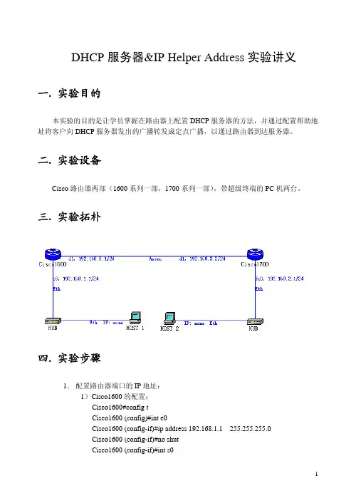
DHCP服务器&IP Helper Address实验讲义一.实验目的本实验的目的是让学员掌握在路由器上配置DHCP服务器的方法,并通过配置帮助地址将客户向DHCP服务器发出的广播转发成定点广播,以通过路由器到达服务器。
二.实验设备Cisco路由器两部(1600系列一部,1700系列一部),带超级终端的PC机两台。
三.实验拓朴四.实验步骤1.配置路由器端口的IP地址:1)Cisco1600的配置:Cisco1600#config tCisco1600 (config)#int e0Cisco1600 (config-if)#ip address 192.168.1.1 255.255.255.0Cisco1600 (config-if)#no shutCisco1600 (config-if)#int s0Cisco1600 (config-if)#ip address 192.168.3.1 255.255.255.0Cisco1600 (config-if)#clock rate 56000Cisco1600(config-if)#no shut2)Cisco1700的配置:Cisco1700#config tCisco1700 (config)#int e0Cisco1700 (config-if)#ip address 192.168.2.1 255.255.255.0Cisco1700 (config-if)#no shutCisco1700 (config-if)#int s0Cisco1700 (config-if)#ip address 192.168.3.2 255.255.255.0Cisco1700(config-if)#no shut2.使用RIP协议作为该网络的路由协议,实现网络的动态路由配置。
完成配置后使用show ip route,show interface,show running-configuration查看路由配置的正确性或者使用ping命令验证网络之间是否完全互连。
配置vlan的DHCP服务(CISCO、H3C)

配置vlan的DHCP服务(CISCO、H3C)1.1.基本要求PC属于vlan10,vlan10的地址段是192.168.10.0/24,开启动态地址分配DHCP,该网段中192.168.10.1-192.168.10.10作为保留IP。
1.2.拓扑结构1.3.配置命令1.3.1.CISCO交换机的设置配置vlanSwitch(config)#vlan 10Switch(config-vlan)#exitSwitch(config)#interface f0/3Switch(config-if)#switchport mode accessSwitch(config-if)#switchport access vlan 10Switch(config-vlan)#exit配置vlan接口地址Switch(config)#interface vlan 10Switch(config-if)#ip address 192.168.10.1 255.255.255.0设置DHCP服务Switch(config)#ip dhcp pool vlan10 //DHCP池名称Switch(dhcp-config)#network 192.168.10.0 255.255.255.0 //DHCP网段Switch(dhcp-config)#default-router 192.168.10.1 //DHCP网关路由Switch(dhcp-config)#dns-server 202.106.0.20 //DNS地址Switch(dhcp-config)#exitSwitch(config)#ip dhcp excluded-address 192.168.10.1 192.168.10.10//保留IP地址段(开始-结束)经过上述配置,讲PC设置为自动获取之后,可从交换机自动得到IP地址、网关、掩码和DMS地址。
思科路由器BFD配置命令详解

Overview of BFD - Static Route SupportThe BFD - Static Route Support feature enables association of static routes with a static Bidirectional Forwarding Detection (BFD) configuration in order to monitor static route reachability using the configured BFD session. Depending on status of the BFD session, static routes are added to or removed from the Routing Information Base (RIB).Unlike dynamic routing protocols, such as OSPF and BGP, static routing has no method of peer discovery. Therefore, when BFD is configured, the reachability of the gateway is completely dependent on the state of the BFD session to the specified neighbor. Unless the BFD session is up, the gateway for the static route is considered unreachable, and therefore the affected routes will not be installed in the appropriate RIB.For a BFD session to be successfully established, BFD must be configured on the interface on the peer and there must be a BFD client registered on the peer for the address of the BFD neighbor. When an interface is used by dynamic routing protocols, the latter requirement is usually met by configuring the routing protocol instances on each neighbor for BFD. When an interface is used exclusively for static routing, this requirement must be met by configuring static routes on the peers.If a BFD configuration is removed from the remote peer while the BFD session is in the up state, the updated state of the BFD session is not signaled to IPv4 static. This will cause the static route to remain in the RIB. The only workaround is to remove the IPv4 static BFD neighbor configuration so that the static route no longer tracks BFD session state. Also, if you change the encapsulation type on a serial interface to one that is unsupported by BFD, BFD will be in a down state on that interface. The workaround is to shut down the interface, change to a supported encapsulation type, and then reconfigure BFD.A single BFD session can be used by an IPv4 static client to track the reachability of next hops through a specific interface. You can assign a BFD group for a set of BFD-tracked static routes. Each group must have one active static BFD configuration, one or more passive BFD configurations, and the corresponding static routes to be BFD-tracked. Nongroup entries are BFD-tracked static routes for which a BFD group is not assigned. A BFD group must accommodate static BFD configurations that can be part of different VRFs. Effectively, the passive static BFD configurations need not be in the same VRF as that of the active configuration.For each BFD group, there can be only one active static BFD session. You can configure the active BFD session by adding a static BFD configuration and a corresponding static route that uses the BFD configuration. The BFD session in a group is created only when there is an active static BFD configuration and the static route that uses the static BFD configuration. When the active static BFD configuration or the active static route is removed from a BFD group, all the passive static routes are withdrawn from the RIB. Effectively, all the passive static routes are inactive until an active static BFD configuration and a static route to be tracked by the active BFD session are configured in the group. Similarly, for each BFD group, there can be one or more passive static BFD configurations and their corresponding static routes to be BFD-tracked. Passive static session routes take effect only when the active BFD session state is reachable. Though the active BFD session state of the group is reachable, the passive static route is added to the RIB only if the corresponding interface state is up. When apassive BFD session is removed from a group, it will not affect the active BFD session if one existed, or the BFD group reachability status.How to Configure BFD - Static Route SupportConfiguring BFD - Static Route SupportPerform this task to configure BFD support for static routing. Repeat the steps in this procedure on each BFD neighbor. For more information, see the “Example: Configuring BFD Support for Static Routing” section.SUMMARY STEPS1.enable2.configure terminal3.interface type number4.ip address ip-address mask5.bfd interval milliseconds min_rx milliseconds multiplier interval-multiplier6.exit7.ip route static bfd interface-type interface-number ip-address [group group-name [passive]]8.ip route [vrf vrf-name] prefix mask {ip-address | interface-type interface-number [ip-address]} [dhcp] [distance] [name next-hop-name] [permanent | track number] [tag tag]9.exit10.show ip static route11.show ip static route bfdConfiguration Examples for BFD - Static Route SupportExample: Configuring BFD - Static Route SupportIn the following example, the network consists of Device A and Device B. Serial interface 2/0 on Device A is connected to the same network as serial interface 2/0 on Device B. In order for the BFD session to come up, Device B must be configured.Device Aconfigure terminalinterface Serial 2/0ip address 10.201.201.1 255.255.255.0bfd interval 500 min_rx 500 multiplier 5ip route static bfd Serial 2/0 10.201.201.2ip route 10.0.0.0 255.0.0.0 Serial 2/0 10.201.201.2Device Bconfigure terminalinterface Serial 2/0ip address 10.201.201.2 255.255.255.0bfd interval 500 min_rx 500 multiplier 5ip route static bfd Serial 2/0 10.201.201.1ip route 10.1.1.1 255.255.255.255 Serial 2/0 10.201.201.1 Note that the static route on Device B exists solely to enable the BFD session between 10.201.201.1 and 10.201.201.2. If there is no useful static route that needs to be configured, select a prefix that will not affect packet forwarding, for example, the address of a locally configured loopback interface.In the following example, there is an active static BFD configuration to reach 209.165.200.225 through Ethernet interface 0/0 in the BFD group testgroup. As soon as the static route is configured that is tracked by the configured static BFD, a single hop BFD session is initiated to 209.165.200.225 through Ethernet interface 0/0. The prefix 10.0.0.0/8 is added to the RIB if a BFD session is successfully established. configure terminalip route static bfd Ethernet 0/0 209.165.200.225 group testgroup ip route 10.0.0.0 255.255.255.224 Ethernet 0/0 209.165.200.225 In the following example, a BFD session to 209.165.200.226 through Ethernet interface 0/0.1001 is marked to use the group testgroup. That is, this configuration is a passive static BFD. Though there are static routes to be tracked by the second static BFD configuration, a BFD session is not triggered for 209.165.200.226 through Ethernet interface 0/0.1001. The existence of the prefixes 10.1.1.1/8 and10.2.2.2/8 is controlled by the active static BFD session (Ethernet interface 0/0 209.165.200.225). configure terminalip route static bfd Ethernet 0/0 209.165.200.225 group testgroup ip route 10.0.0.0 255.255.255.224 Ethernet 0/0 209.165.200.225ip route static bfd Ethernet 0/0.1001 209.165.200.226 group testgroup passiveip route 10.1.1.1 255.255.255.224 Ethernet 0/0.1001209.165.200.226ip route 10.2.2.2 255.255.255.224 Ethernet 0/0.1001209.165.200.226Additional References for BFD - Static Route Support。
cisco路由器的参数和功能知识
cisco路由器的参数和功能知识Cisco(思科)路由器是一种网络设备,被广泛应用于各种规模的网络环境中。
它具备丰富的参数和功能,为网络管理员提供了高度灵活和强大的配置选项。
本文将介绍Cisco路由器的参数和功能知识。
一、路由器参数知识1. IP地址:IP(Internet Protocol)地址是计算机在网络中唯一标识的地址。
Cisco 路由器支持IPv4和IPv6协议,管理员可以配置IP地址以及子网掩码来正确地划分网络。
2. 网关:网关是连接两个不同网络的设备,通常是路由器。
Cisco 路由器可以作为默认网关,将数据包从本地网络转发到其他网络。
3. 路由表:路由表是路由器存储的一份记录。
其中包含了网络之间的最佳路径,路由器通过查找路由表来决定数据包的转发方向。
4. ARP(Address Resolution Protocol):ARP是用于解析网络层地址(IP地址)和物理层地址(MAC地址)之间对应关系的协议。
路由器可以维护ARP缓存表,记录IP地址和MAC地址的映射关系。
5. NAT(Network Address Translation):NAT是一种将私有IP地址转换为公共IP地址的技术,用于解决IP地址短缺问题。
Cisco 路由器支持多种NAT方式,如静态NAT、动态NAT和PAT(Port Address Translation)。
二、路由器功能知识1. 路由:路由器最主要的功能就是进行数据包的路由转发。
路由器可以通过学习路由协议(如OSPF、RIP等)来更新路由表,并根据最佳路径将数据包转发到目标网络。
2. ACL(Access Control List):ACL是一种基于网络流量的过滤机制,通过对数据包的源、目的IP地址、协议、端口等进行匹配,来决定是否允许或拒绝数据包通过路由器。
3. DHCP(Dynamic Host Configuration Protocol):DHCP是一种自动分配IP地址的协议,可以通过路由器为网络中的设备提供动态IP地址、DNS服务器地址、网关地址等信息。
cisco路由器三层交换机简单环境配置实例
cisco路由器三层交换机简单环境配置实例随着Internet的高速发展,网络规模不断膨胀,对于从事网络专业的学生熟练掌握路由器和交换机的配置已显得十分重要。
接下来是小编为大家收集的cisco路由器三层交换机简单环境配置实例方法,希望能帮到大家。
cisco路由器三层交换机简单环境配置实例:一、网络拓扑图:二、配置命令:1、路由器的配置:interface FastEthernet0/0ip address 10.66.88.222 255.255.255.0ip nat outsideduplex autospeed autointerface FastEthernet0/1ip address 192.168.1.1 255.255.255.0ip nat insideduplex autospeed autointerface Vlan1no ip addressshutdownip nat inside source list 1 interface FastEthernet0/0 overload ip classlessip route 192.168.2.0 255.255.255.0 192.168.1.222ip route 192.168.3.0 255.255.255.0 192.168.1.222access-list 1 permit 192.168.0.0 0.0.255.255三、三层交换机的配置:hostname L3-SWip dhcp pool vlan2poolnetwork 192.168.3.0 255.255.255.0 default-router 192.168.3.1dns-server 202.101.172.35ip dhcp pool vlan1poolnetwork 192.168.2.0 255.255.255.0 default-router 192.168.2.1dns-server 202.101.172.35interface FastEthernet0/1no switchportip address 192.168.1.222 255.255.255.0 duplex autospeed autointerface FastEthernet0/2 switchport mode trunkinterface FastEthernet0/5 switchport mode trunkinterface Vlan1ip address 192.168.2.1 255.255.255.0 interface Vlan2ip address 192.168.3.1 255.255.255.0 ip classlessip route 0.0.0.0 0.0.0.0 192.168.1.1四、二层交换机的配置:1、switch0的配置:hostname sw0interface FastEthernet0/1 switchport mode trunkinterface FastEthernet0/2 switchport mode access2、switch1的配置:hostname sw1interface FastEthernet0/1switchport mode trunkinterface FastEthernet0/2switchport access vlan 2switchport mode access看了“cisco路由器三层交换机简单环境配置实例”还想看:1.思科交换机基本配置实例讲解2.三层交换机配置的实例教程3.cisco路由器怎么在虚拟环境下配置三层交换4.cisco2960交换机的简单配置5.交换机配置基础及实例讲解6.思科三层交换机与路由器的比较方法7.思科交换机配置教程详解。
DHCP配置方法
DHCP配置命令dhcp(dynamic host configuration protocol)动态主机配置协议,它是基于客户机-服务器模式的协议,dhcp服务器能从dhcp地址池中把ip地址分配给请求的dhcp客户机,同时也能够为其提供其它网络配置参数,如缺省网关、dns服务器、缺省路由和网络范围内主机映像文件的位置等。
dhcp服务器的配置命令:1 bootfile2 clear ip dhcp binding3 clear ip dhcp conflict4 clear ip dhcp server5 client-identifier6 client-name7 default-router8 dns-server9 domain-name10 host11 hardware-address12 ip dhcp conflict logging13 excluded-address14 ip dhcp pool15 ip dhcp ping packets16 ip dhcp ping timeout17 lease18 netbios-name-server19 netbios-node-type20 network21 next-server22 option23 service dhcp24 show ip dhcp binding25 show ip dhcp conflict26 show ip dhcp server statistics27 debug ip dhcp serverdhcp中继的配置命令:1 ip dhcp relay information policy drop2 ip forward-protocol udp3 ip help-address4 show ip helper-address5 show forward-protocol6 debug forward-protocol4.1.4.1 bootfile命令:bootfile [filename]no bootfile功能:配置dhcp客户机的启动时的导入文件名;本命令的no操作为删除该项配置。
华为路由交换配置DHCP及DHCP中继(课堂PPT)
当DHCP Client发现DHCP Server分配给它的IP地址无 法使用,将发出此报文,通知DHCP Server禁止使用该 IP地址
DHCP协议的8种报文(续)
➢ DHCPACK
DHCP Server对DHCP Client的DHCPREQUEST报文的 确认响应报文
DHCP协议特点
➢ 整个配置过程自动实现,DHCP Client端无需配置 ➢ 所有配置信息由DHCP Server统一管理 ➢ 通过IP地址租期管理,提高IP地址的使用效率 ➢ 采用广播实现报文交互,报文一般不能跨网段,如
果需跨网段,需要使用DHCP Relay技术实现
DHCP协议系统组成
➢ DHCP Client
➢ Manual Allocation
网络管理员为某些少数特定的主机绑定固定IP地址,且 地址不会过期
DHCP协议分配地址的优先级
➢ DHCP Server数据库中与该DHCP Client的MAC地址静 态绑定的IP地址
➢ 该DHCP Client曾经使用过的地址 ➢ 顺序查找DHCP地址池中可供分配的IP地址,最先找到的
chaddr(16)
sname(64)
file(128)
options (variable)
DHCP报文中各个部分的含义
字段 op htype hlen hops
xid
secs flags
含义
message op code / message type “1“代表BOOTREQUEST ”2“代表 BOOTREPLY
DHCP Client通过DHCP协议来获得网络配置参数 通常是一台主机或网络设备
➢ DHCP Server
Cisco 3750交换机配置DHCP
Cisco 3750交换机配置DHCP2009-02-27 14:53Cisco 3750交换机配置DHCP服务器实例网络环境:一台3750交换机,划分三个vlan, vlan2 为服务器所在网络,命名为server,IP地址段为192.168.2.0,子网掩码:255.255.255.0,网关:192.168.2.1,域服务器为windows 2003 advance server,同时兼作DNS服务器,IP地址为192.168.2.10,vlan3为客户机1所在网络,IP地址段为192.168.3.0,子网掩码:255.255.255.0,网关:192.168.3.1命名为work01,vlan4为客户机2所在网络,命名为work02,IP地址段为192.168.4.0,子网掩码:255.255.255.0,网关:192.168.4.1,3750作DHCP服务器,端口1-8划到VLAN 2,端口9-16划分到VLAN 3,端口17-24划分到VLAN 4.DHCP服务器实现功能:各VLAN保留2-10的IP地址不分配置,例如:192.168.2.0的网段,保留192.168.2.2至192.168.2.10的IP地址段不分配.安全要求:VLAN 3和VLAN 4 不允许互相访问,但都可以访问服务器所在的VLAN 2, 默认访问控制列表的规则是拒绝所有包。
配置命令及步骤如下:第一步:创建VLAN:Switch>enSwitch#Vlan DatabaseSwitch(Vlan)>Vlan 2 Name serverSwitch(Vlan)>Vlan 3 Name work01Switch(vlan)>Vlan 4 Name work02第二步:设置VLAN IP地址:Switch#Config TSwitch(Config)>Int Vlan 2Switch(Config-vlan)Ip Address 192.168.2.1 255.255.255.0Switch(Config-vlan)No ShutSwitch(Config-vlan)>Int Vlan 3Switch(Config-vlan)Ip Address 192.168.3.1 255.255.255.0Switch(Config-vlan)No ShutSwitch(Config-vlan)>Int Vlan 4Switch(Config-vlan)Ip Address 192.168.4.1 255.255.255.0Switch(Config-vlan)No ShutSwitch(Config-vlan)Exit/*注意:由于此时没有将端口分配置到VLAN2,3,4,所以各VLAN会DOWN 掉,待将端口分配到各VLAN后,VLAN会起来*/第三步:设置端口全局参数Switch(Config)Interface Range Fa 0/1 - 24Switch(Config-if-range)Switchport Mode AccessSwitch(Config-if-range)Spanning-tree Portfast第四步:将端口添加到VLAN2,3,4中/*将端口1-8添加到VLAN 2*/Switch(Config)Interface Range Fa 0/1 - 8Switch(Config-if-range)Switchport Access Vlan 2/*将端口9-16添加到VLAN 3*/Switch(Config)Interface Range Fa 0/9 - 16Switch(Config-if-range)Switchport Access Vlan 3/*将端口17-24添加到VLAN 4*/Switch(Config)Interface Range Fa 0/17 - 24Switch(Config-if-range)Switchport Access Vlan 4Switch(Config-if-range)Exit/*经过这一步后,各VLAN会起来*/第五步:配置3750作为DHCP服务器/*VLAN 2可用地址池和相应参数的配置,有几个VLAN要设几个地址池*/ Switch(Config)Ip Dhcp Pool Test01/*设置可分配的子网*/Switch(Config-pool)Network 192.168.2.0 255.255.255.0/*设置DNS服务器*/Switch(Config-pool)Dns-server 192.168.2.10/*设置该子网的网关*/Switch(Config-pool)Default-router 192.168.2.1/*配置VLAN 3所用的地址池和相应参数*/Switch(Config)Ip Dhcp Pool Test02Switch(Config-pool)Network 192.168.3.0 255.255.255.0Switch(Config-pool)Dns-server 192.168.2.10Switch(Config-pool)Default-router 192.168.3.1/*配置VLAN 4所用的地址池和相应参数*/Switch(Config)Ip Dhcp Pool Test03Switch(Config-pool)Network 192.168.4.0 255.255.255.0Switch(Config-pool)Dns-server 192.168.2.10Switch(Config-pool)Default-router 192.168.4.1第六步:设置DHCP保留不分配的地址Switch(Config)Ip Dhcp Excluded-address 192.168.2.2 192.168.2.10 Switch(Config)Ip Dhcp Excluded-address 192.168.3.2 192.168.3.10 Switch(Config)Ip Dhcp Excluded-address 192.168.4.2 192.168.4.10第七步:启用路由/*路由启用后,各VLAN间主机可互相访问*/Switch(Config)Ip Routing第八步:配置访问控制列表Switch(Config)access-list 103 permit ip 192.168.2.0 0.0.0.255 192.168.3.0 0.0.0.255Switch(Config)access-list 103 permit ip 192.168.3.0 0.0.0.255 192.168.2.0 0.0.0.255Switch(Config)access-list 103 permit udp any any eq bootpcSwitch(Config)access-list 103 permit udp any any eq tftpSwitch(Config)access-list 103 permit udp any eq bootpc anySwitch(Config)access-list 103 permit udp any eq tftp anySwitch(Config)access-list 104 permit ip 192.168.2.0 0.0.0.255 192.168.4.0 0.0.0.255Switch(Config)access-list 104 permit ip 192.168.4.0 0.0.0.255 192.168.2.0 0.0.0.255Switch(Config)access-list 104 permit udp any eq tftp anySwitch(Config)access-list 104 permit udp any eq bootpc anySwitch(Config)access-list 104 permit udp any eq bootpc anySwitch(Config)access-list 104 permit udp any eq tftp any第九步:应用访问控制列表/*将访问控制列表应用到VLAN 3和VLAN 4,VLAN 2不需要*/Switch(Config)Int Vlan 3Switch(Config-vlan)ip access-group 103 outSwitch(Config-vlan)Int Vlan 4Switch(Config-vlan)ip access-group 104 out第十步:结束并保存配置Switch(Config-vlan)EndSwitch#write memory。