诺瓦科技LED地砖屏接收卡TBR200详细规格说明书英语版
诺瓦科技LED透明屏接收卡MRV316详细参数说明书英语版
MRV316Product DescriptionDocument Version:V1.0.0Receiving CardDocument Number: NS110100375Copyright © 2017 Xi’an NovaStar Tech Co., Ltd. All Rights Reserved.No part of this document may be copied, reproduced, extracted or transmitted in any form or by any means without the prior written consent of Xi’an NovaStar Tech Co., Ltd. Product Description Change HistoryProduct DescriptionContentsChange HistoryTrademarkis a registered trademark of Xi’an NovaStar Tech Co., Ltd.StatementYou are welcome to use the product of Xi’an NovaStar Tech Co., Ltd. (hereinafter referred to as NovaStar ). This document is intended to help you understand and use the product. For accuracy and reliability,NovaStar may make improvements and/or changes to this document at any time and without notice. Any problem in use or any good suggestion, please contact u s through ways provided in the document. We will do our utmost to solve the problems and adopt the suggestions after evaluation as soon as possible.Receiving Card MRV316ContentsChange History (ii)1Safety (1)2Overview (2)3F eatures (3)4Hardware (4)4.1Appearance (4)4.2Dimensions (5)4.3Indicators (5)4.4Definition of Data Interface (6)5Software Structure (8)Typical Networking ...................................................................................................................... 69 7 Specifications . (11)1 Safety1 SafetyThis chapter illustrates safety of the MRV316 receiving card to ensure the product’sstorage, transport, installation and use safety. Safety instructions are applicable to allpersonnel who contact or use the product. First of all, pay attention to following points.●Read through the instructions.●Retain all instructions.●Comply with all instructions.Storage and Transport Safety●Pay attention to dust and water prevention.●Avoid long-term direct sunlight.●Do not place the product at a position near fire and heat.●Do not place the product in an area containing explosive materials.●Do not place the product in a strong electromagnetic environment.●Place the product at a stable position to prevent damage or personal injurycaused by dropping.●Save the packing box and materials which will come in handy if you ever have tostore and ship the product. For maximum protection during storage and shipping,repack the product as it was originally packed at the factory.Installation and Use Safety●Only trained professionals may install the product.●Plugging and unplugging operations are prohibited when the power is on.●Ensure safe grounding of the product.●Always wear a wrist band and insulating gloves.●Do not place the product in an area having frequent or strong shake.●Perform dust removing regularly.●Contact NovaStar for maintenance at any time, rather than have the productdisassembled and maintained by non-professionals without authorization.●Replace faulty parts only with the spare parts supplied by NovaStar.2 Overview2OverviewThe MRV316 is a new receiving card developed by NovaStar. A single MRV316 loads up to 512x256 pixels.The MRV316 supports pixel level brightness and chroma calibration, which effectively removes color difference, greatly improves display consistency of LED images, and presents finer displays to users.Software and hardware designs of the MRV316 have fully concerned users' deployment, operating and maintenance scenarios, enabling easier deployment, more stable operating and more efficient maintenance.Hardware design:●Integrates 16 standard HUB75 connectors, which makes the HUB boardunnecessary.●Adopts the Gigabit Ethernet port, which can connect to the PC.Software design:●Supports pixel level brightness and chroma calibration.●Supports setting of images pre-stored in the receiving card.●Supports status detection of temperature, voltage, Ethernet cablecommunication and video source signals.●Supports the 5-pin LCD module.4Hardware4.1 AppearanceProduct images provided in this file are for reference only, and the actual productsshall prevail.4.2 DimensionsThe board thickness is not greater than 2.0 mm, and the total thickness (boardthickness + thickness of components on front and rear panels) is not greater than17.5 mm.The u n it of dimension chart is “mm”. The location holes are connected to signa lgrounds (GND).4.3Indicators4Powerindicator (red)Always onThe indicator will be always on after the power is on.4.45 SoftwareStructure5Software StructureFirmware in the delivery MRV316 includes MCU program and FPGA program. Program download method:Visit w ww.novastar-led.c n a nd change the user interface language to English at the top right. Then, on the displayed P roducts&Downloads page, click the target receiving card in the R eceiving Card section to enter its detail introduction page. At last, click D ownloads to enter the download list and download the required program packages.6 TypicalNetworkingReceiving Card MRV316Product Description6 Typical NetworkingFigure 6-2 No sending card mode6Typical NetworkingThe MRV316 is applied to the LED display synchronous system which is generally composed of the LED display, receiving card, LED display controller and controller peripherals. The receiving card is connected to the LED display over HUB connectors.The synchronous system requires connecting a computer to display the computer’s images and texts on the LED display. The synchronous system's structure is shown in the following figure.Figure 6-1 Sending card mode7 Specifications。
诺瓦科技LED接收卡XC200规格书
西安诺瓦电
产品规格书
接收卡 XC200
Rev1.1.2 NS110000194
概述
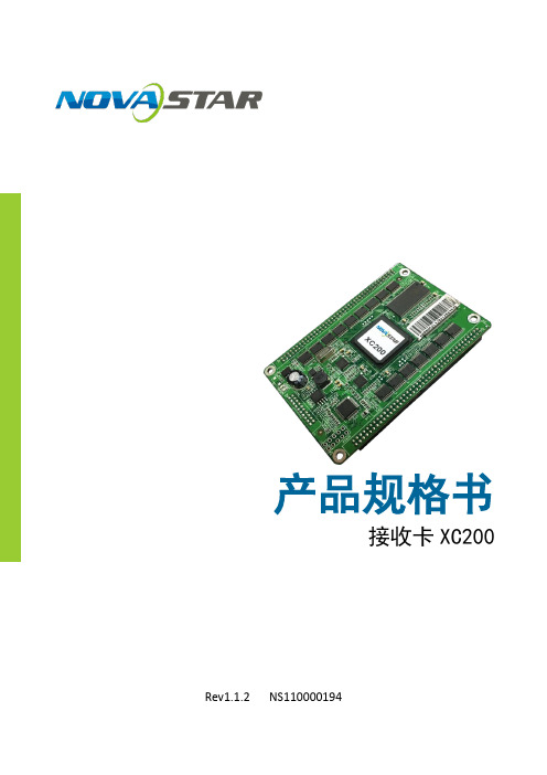
XC200 是诺瓦 M3 系列的高密度接收卡。与传统接收卡相比,XC200 使用更
灵活。
XC200 单卡可带载 512×384 像素,支持灯板 flash 或者智能模组管理、液晶
屏人机交互、自带电压温度检测等实用功能。XC200 特定的电路和程序设计,
16
17
OE_RED
CTRL
18 17
DATA44
DATA45
18
19
E
D
20 19
DATA46
DATA47
20
21
C
B
22 21
DATA48
DATA49
22
23
A
LAT
24 23
DATA50
DATA51
24
25
DCLK
GND
26 25
DATA52
DATA53
26
27
NC
NC
28 27
DATA54
DATA55
司 能有效降低系统的电磁辐射,力助用户产品轻松通过 EMC 认证。
功能特性
限公
1) 单卡最大输出 RGB 数据 32 组。
有
2) 单卡带载像素为 512×384。
技
科 3) 支持 1~1/32 扫之间的任意扫描类型,支持 595 等串行译码扫描。
4) 支持常规芯片、PWM 芯片等所有主流 LED 驱动芯片。
子 5) 支持高灰阶高刷新率。 电 6) 支持亮色度逐点校正。 瓦 7) 完美异型支持:任意走线、任意抽点、异型灯板、异型箱体、异型屏,轻
诺瓦科技LED显示屏接收卡MRV360规格书英文版
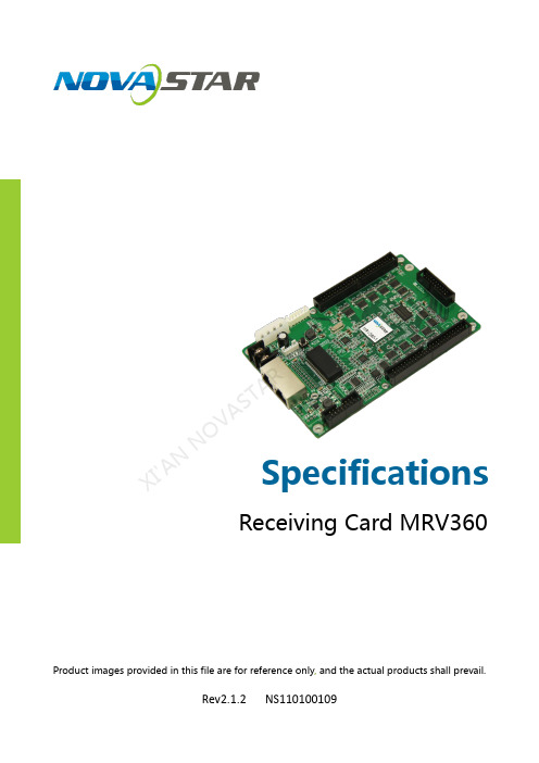
SpecificationsReceiving Card MRV360Product images provided in this file are for reference only , and the actual products shall prevail.Rev2.1.2NS110100109XI 'AN NOVA S TAR T E C H C O .,L T D.OverviewNova M3 MRV360 is one model of Nova receiving card. It has the interface of MOM(Memory On Module).Features1) Single card outputs 16-group of RGBR 'data; 2) Single card outputs 20-group of RGB data;3) Single card outputs 64-group of serial data;4) Supporting MOM management, MOM can store calibrationcoefficient and the LED module information; 5) Single card supports resolution of 256x226; 6) Configuration file readback; 7) Temperature monitoring; 8) Ethernet cable communication status detection; 9) Power supply voltage detection; 10) Pixel-by-pixel brightness and chromaticity calibration.Brightness and chromaticity calibration coefficients for each LED; 11) Pre-store picture setting; 12) Able to connect monitoring card; 13) Comply with EU RoHs standard;14) Comply with EU CE-EMC Class A standard.XI 'A N N O V A S T A R T E C H C O .,L T D.Output Interface DefinitionUnder all the three different working modes of it, two 50P interfaces can output different data, and only one common program and software are required. No customized program is needed. Interfaces are defined as follows:1) 16-group data modeSupporting 16-group of RGBR 'parallel data, defined as follows:Virtual R signal in the last data group of each 50pin hub is decodingsignal E at 1/32 scan mode.X I 'AN NOVA S TAR T E C HCO .,L T D.2) 20-group parallel data modeSupporting 20 sets of parallel data, defined as follows:XI 'A N N O VA S T A R T E C HCO3) 64-group serial data modeSupporting 64 sets of serial data, defined as follows:Under serial mode, there are 64 data cables totally. Each cable can drive one LED bar independently.XI 'A N N O V A S T A R T EIn case of horizontal LED bar, the default is that Data1 drives the first row from the top, and Data64 drives the 64th row. (front view).In case of vertical LED bar, the default is that Data1 drives the first column of from the left, and Data64 drives the 64th column. (front view).Thickness of the board is about 1.6mm. The overall thickness (board thickness+thickness of the components on front and back side) is about 18.5mm.Unit: mm.X I'A NN OV AS TA RT EC HC O.,L TD.Note: Product images provided in this file are for reference only, and the actual products shall prevail.J4(MOM interface )defintion :J9 definition (Indicator light Socket )J10 definition (Indicator Socket ):T E C H C OSpecific Model ListTo meet the needs of different customers, Nova has provided more specific models of the products, including standard products in stock. Other models need to be customized.E C H C O .,L T D.Serial data decoding circuit:X I'A NN OV AS TA RT EC HC O.,L TD.。
诺瓦科技LED显示屏接收卡XC100规格书英文版

SpecificationsReceiving Card XC100Rev1.2.1NS110100191XI 'AN NOVA S T AR T E C H CO .,LT D.OverviewXC100 is super-small full function high-end mini receiving card rolled out lately by NovaStar. Compared with traditional receiving card, XC100 is more flexible in usage and DDR3 SODIMM port adopted renders it to adapt to various electrical structures easily; as a result, one module card is suitable for all applications, greatly reducing the types of module cards to be purchased.XC100 single card can load pixel of 256*256, supporting such utility functions as intelligent module management, LED display human-computer interaction and built-in voltage temperature detection. Specific circuit and program design of XC100 can effectively reduce electromagnetic radiation of the system, helping users to make their products pass EMC certification easily.Such a powerful XC100 is bound to usher in a new age of receiving card! Features 1) Single card supports pixel points of 256*256.2) Single card supports parallel output of 24-module RGB signal, extending to parallel data of 48-module RGB at maximum.3) Any scanning types within 1-1/32 scan and 595 serial decoding scanning aresupported.4) All mainstream LED driving chip like regular chip and PWM chip are supported. 5) High gray scale and high refresh rate is supported. 6) Pixel-by-pixel calibration of brightness degree is supported.7) Perfect special shape support; Random alignment, random test pixel, special-shapedmodule, special-shaped cabinet and special-shaped LED display make load more easily.8) Seamless switching of various hot backups including loop backup, dual card backup,dual power supply backup, etc. are supported.9) Human-computer interaction of cabinet and LED display is supported. 10) One-way voltage and temperature detection is available.11) Intelligent module is supported, with the functions of storing and managing calibrationcoefficient, module information and moudle parameters, as well as row line detection and LED pixel-by-pixel error detection without the need of monitoring card. 12) Special EMC design effectively reduces electromagnetic radiation.XI 'A N N O VA S T A R T E C H C O .,LT D.AppearanceNotes1: Positioning hole is connected to GND.DimensionsUnit: mmXI 'AN NOVA S T AR T E C H CO .,LT D.Output Interface DefinitionIntelligentmodule portX I'A NN OV AS TA RT EC HC O.,L TD.Gigabit network portX I N OV AS TA RT EC HC O.,L TD.X IX ISpecifications X I T E C。
诺瓦科技LED透明屏接收卡TR100规格书产品说明书

接收卡规格书产品版本:V1.0.0文档编号:NS120000328接收卡TR100规格书www.novastar-l 更新记录V1.0.0i接收卡TR100规格书www.novastar-l ed.c n目录1概述 (1)2产品特性 (2)2.1提升显示效果 (2)2.2提升可维护性 (2)2.3提升硬件可靠性 (3)2.4提升软件可靠性 (3)3接口定义 (4)3.1 32组并行数据接口 (4)3.2扩展功能参考设计 (7)4外观 (8)5尺寸 (9)6产品规格 (10)接收卡TR100规格书www.novastar-l ed.c n1概述TR100是诺瓦科技推出的新一代接收卡,单卡带载384×384像素。
TR100支持1.0/2.3(S AA)同轴接口,使系统的连接和数据传输更加可靠。
支持SerDes技术,具有低延迟特性。
同时,T R100支持18B it+灰度输出,有效处理LED显示屏因亮度降低带来的灰度损失问题,使图像更细腻。
接收卡TR100规格书规格书备注2.RGB 数据组必须成组使用。
备注3.运行指示灯为低电平有效。
备注4.OE_RED、OE_GREEN、OE_BLUE 为显示使能引脚。
OE_RGB 不分开控制时,使用OE_RED。
当使用PWM 芯片时,为GCLK 信号。
备注5.RFU1~18 是预留扩展功能接口,详细信息请参见“3.2 扩展功能参考设计”。
规格书www.novastar-l ed.c n4外观本文中的产品照片仅供参考,实际出厂产品安装散热片,请以实际购买到的产品为准。
TR100使用的高密度接插件的母座(R eceptacle)型号如表4-1所示。
公座(P LUG)型号可以根据实际需求选择。
4-1规格书www.novastar-l ed.c n5尺寸(单位:m m)。
诺瓦科技LED接收卡MRV328产品说明书英文版

Receiving CardMRV328Document Version:V1.0.0Document Number: NS110100409Product Description XI 'AN N O VA S T AR T E C H CO .,LT D.Copyright © 2018 Xi’an Nov aStar Tech Co., Ltd. All Rights Reserved.No part of this document may be copied, reproduced, extracted or transmitted in any form or by any means without the prior written consent of Xi’an NovaStar Tech Co., Ltd.Trademarkis a registered trademark of Xi’an NovaStar Tech Co., Ltd.StatementYou are welcome to use the product of Xi’an NovaStar Tech Co., Ltd. (hereinafter referred to as NovaStar). This document is intended to help you understand and use the product. For accuracy and reliability, NovaStar may make improvements and/or changes to this document at any time and without notice. Any problem in use or any good suggestion, please contact us through ways provided in the document. We will do our utmost to solve the problems and adopt the suggestions after evaluation as soon as possible.X I'A NN OV AS TA RT EC HC O.,L TD.Product Description Change HistoryChange HistoryX I'A NN OV AS TA RT EC HC O.,L TProduct Description ContentsContentsChange History (ii)1 Safety (1)2 Overview (2)3 Features (3)4 Hardware Structure (4)4.1 Appearance (4)4.2 Dimensions (5)4.3 Indicators (5)4.4 Definition of Data Interface (6)5 Software Structure (7)6 Typical Networking (8)7 Specifications (10)X I'A NN OV AS TA RT EC HC O.,L TD.Product Description1 Safety1SafetyThis chapter illustrates safety of the MRV328 receiving card to ensure the produc t’s storage, transport, installation and use safety. Safety instructions are applicable to all personnel who contact or use the product. First of all, pay attention to following points.● Read through the instructions. ● Retain all instructions. ●Comply with all instructions.Storage and Transport Safety● Pay attention to dust and water prevention. ● Avoid long-term direct sunlight.● Do not place the product at a position near fire and heat.● Do not place the product in an area containing explosive materials. ● Do not place the product in a strong electromagnetic environment. ● Place the product at a stable position to prevent damage or personal injury caused by dropping.●Save the packing box and materials which will come in handy if you ever have to store and ship the product. For maximum protection during storage and shipping, repack the product as it was originally packed at the factory.Installation and Use Safety● Only trained professionals may install the product.● Plugging and unplugging operations are prohibited when the power is on. ● Ensure safe grounding of the product.● Always wear a wrist band and insulating gloves.● Do not place the product in an area having frequent or strong shake. ● Perform dust removing regularly.● Contact NovaStar for maintenance at any time, rather than have the productdisassembled and maintained by non-professionals without authorization. ●Replace faulty parts only with the spare parts supplied by NovaStar.XI 'AN NOVA S T AR T E C H CO .,LT D.2OverviewThe MRV328 is a new receiving card developed by NovaStar. A single MRV328 loads up to 256x256 pixels.The MRV328 supports pixel level brightness and chroma calibration, which effectively removes color difference, greatly improves display consistency of LED images, and presents finer displays to users.Software and hardware designs of the MRV328 have fully concerned users'deployment, operating and maintenance scenarios, enabling easier deployment, more stable operating and more efficient maintenance.Hardware design:● Integrates 8 standard HUB75 connectors, which makes the HUB board unnecessary.●Adopts the Gigabit Ethernet port, which can connect to the PC.Software design:● Supports pixel level brightness and chroma calibration. ● Supports setting of images pre-stored in the receiving card. ● Supports status detection of temperature, voltage, Ethernet cable communication and video source signals. ●Supports the 5-pin LCD module.XI 'AN NOVA S T AR T E C H CO .,LT D.3FeaturesXI 'A.4Hardware Structure4.1 AppearanceProduct images provided in this file are for reference only, and the actual products shall prevail.XI 'AN NOVA S T AR T E C H CO .,LT D.4.2 DimensionsThe board thickness is not greater than 2.0 mm, and the total thickness (board thickness + thickness of components on front and rear panels) is not greater than 17.0 mm.The unit of dimension chart is “mm”. T he location holes are connected to signal grounds (GND).4.3 IndicatorsXI 'A S T AR T E C H CO .,LT D.4.4 Definition of Data InterfaceX I'A RT EC HC O.,L TD.Product Description 5 Software Structure5 Software StructureMethod of downloading the firmware upgrade package:Visit www.novastar.tech and choose Download > Firmware. On the Firmwaresection, choose the desired program package to download.X I'A NN OV AS TA RT EC HC O.,L TD.6 Typical Networking The MRV328 is applied to the LED display synchronous system which is generally composed of the LED display, receiving card, LED display controller (optional) and controller peripherals. The receiving card is connected to the LED display over HUB connectors.The synchronous system requires connecting a computer to display the computer’s images and texts on the LED display. The synchronous system's structure is shownin the following figure.Figure 6-1 Sending card modeX I'A NN OV AS TA RT EC HC O.,L TD.Figure 6-2 No sending card modeX I'A NN OV AS TA RT EC HC O.,L TD.Product Description 7 Specifications7 SpecificationsX I'A N.。
诺瓦科技LED视频处理器VP200U用户手册英文版
StatementWelcome to use the product from Xi ’an NovaStar T ech Co., Ltd. (hereinafter referred to as “NovaStar ”). It is our great pleasure to offer this manual to help youunderstand and use the product. We have striven for precision and reliability during the compilation of this manual. The contents of this manual are subject to change without notice. If you have any problem in use or you have any suggestion, please feel free to contact us according to the contact information provided in this manual. We will do our utmost to satisfy your needs. We would like to express our sincere thanks to your suggestions and make assessment for adoption as soon as possible.CopyrightAll the intellectual property rights involved in this document belong to NovaStar.Unauthorized duplication is a violation of applicable laws.Trademarkis the registered trademark of NovaStar.Safety StatementTo avoid potential hazards, please use this unit according to regulations. In the event of breakdowns, non-professionals are not allowed to disassemble it for maintenance without permission. Please contact the after-sales department ofNovaStar. Power outlet should be installed near the unit and easy to reach.High voltage danger: The operating voltage range of this product is100-240V AC.Grounding: This product is grounded through grounding cord of powersupply. Please keep the grounding conductor well grounded.Electromagnetic interference: Keep this product far away from magnets, motors and transformers.Moisture proof: Keep this product in a dry and clean environment. In case of liquid immersion, please pull the power plug out immediately. Keep the product away from flammable and explosive hazardous substance.Prevent liquids or metal fragments from dropping into the product in order to avoid safety accidents.Xi ’an No v aS t ar Te c hC o .,L t d .TABLE OF CONTENTSChapter 1 Overview ............................................................................................... 1 Chapter 2Function Brief ...................................................................................... 2 Input/Output Interface Diagram ..................................................................... 2 Front Panel Control Display Diagram (2)Electrical Parameters ........................................................................................... 4 Chapter 3Signal Connection ............................................................................... 5 Signal Connection ................................................................................................ 5 Multiple Units Connection .. (5)Chapter 4 Menu Operations ................................................................................ 6 Main Interface........................................................................................................ 6 Main Menu . (7)Output Settings ..................................................................................................... 8 PIP .............................................................................................................................. 8 Image Crop . (9)Picture Settings (10)Image Switching ................................................................................................ 10 Misc Settings ....................................................................................................... 11 Uplay settings ..................................................................................................... 12 Language/菜单语言 ........................................................................................... 12 Chapter 5 Quick Operation Guide ..................................................................... 13 Chapter 6 FAQ (16)Xi ’an No v aS t ar Te c hC o .,L t d .Chapter 1OverviewVP200U is a video processor developed for the display system of large-size LED displays. With the leading-edge chips of the industry used and 12-bit digital processing inside, it will bring us clearer images and richer colors. VP200U has adopted technologies such as Faroudja® DCDI de-interlacing video processing, Real Color® real color image processing, Faroudja®TureLife™ video image enhancement, etc. to perfect the display of video image.The maximum output resolution of a single unit is up to 2304x1152 and it allows to customize output resolution. VP200U has multiple special switching effects like signal cut and fade. The size and position of PIP (Picture in Picture) can be set as you wish and AIAO (Any In Any Out) is supported.In addition, VP200U supports USB drive play with the feature of automatic detection and plug-and-play, which has made it much easier and more flexible to use.X i’a n No v aS t ar Te c hC o.,Lt d.Chapter 2 Function BriefInput/Output Interface DiagramFront Panel Control Display DiagramXi ’an d .Shortcut operations:MENU: Press and hold the button to call out brightness adjusting menu when inmain interface; Press and hold the button to directly return to main interface when in menu mode. MODE: Press “MODE” to enter “Load Model” interface and then press “AUTO”to save model.Xi ’an No v aS t ad .Electrical Parametersd.Chapter 3 Signal ConnectionSignal ConnectionTwo sending cards can be installed in the unit and a single unit can drive a LED display with 2304*1152 pixels.The unit supports 8-channel analog and digital signal inputs at most.Tip: Please turn off the power during signal connection.Multiple Units ConnectionNote: This connection mode is applied to synchronous loading of processor models, namely, save the models in advance and then press one button for synchronous load when multiple units are connected.Load model: Press “MODE ” on the front panel and the Load Model interface appears. Press NUM key to load model.Save model: Enter “Load Model ” interface via shortcut and press “AUTO ” to switch to “Save Model ” interface. Then press NUM key to save. It only can save for each unit separately.Xi ’an No v aS t ar T e chC o .,L t d .Chapter 4 Menu OperationsMain InterfaceSwitch on the processor and the main interface on operation screen is shown as follows:1st line: Channel1, signal source, format of input signal; 2nd line: Channel2, signal source, format of input signal; 3rd line: Output, resolution and refresh rate of output signal;4th line: Status line, the meaning of each icon is described as follows;:PIP closed;: PIP opened, Channel1 picture is moved to the top layer; : PIP opened, Channel2 picture is moved to the top layer;: Part function is enabled and size of output image is the same as window size ; : Full screen function is enabled and the size of output image is the same as the input size;: Channel1 Image Crop is closed and the output is complete image; : Channel1 Image Crop is opened and the output is cropped image; : Channel2 Image Crop is closed and the output is complete image; : Channel2 Image Crop is opened and the output is cropped image; : Freeze is opened and current output image is frozen; : Current USB drive is set to single round play; : Current USB drive is set to list round play; : USB drive hasn't been plugged; : USB drive has been plugged;: USB drive has been plugged, but the format of USB drive is not supported.Xi ’an No v aS t ar Te c hC o .,L t d .Main MenuPress the knob when in the main interface to enter menu operation interface, then press the knob to enter submenus. Press “ESC” button to back to previous level and press and hold the knob to directly back to the main interface.Match Method, Horizontal Resolution,Vertical Resolution, Apply, Restore DefaultXi ’d .Output SettingsSet output resolution and output window size.Note: the steps of output settings for LED display: 1)Choose a suitable resolution (the number of horizontal pixels and vertical pixels of the selected resolution are greater than that of the LED display) Set “H -Width” and “V -Height” according to the size of the LED display;2) Horizontal start and vertical start are the same as the horizontal and vertical start of sending card. Generally, they are set to 0;3)Full/Part: It is part display by default after the width and height are set, that is, zoomed-out picture will be shown on LED display; When full display is selected, the output image, the size of which is the resolution selected, may be beyond the screen; 4) Custom resolution: Max. output of a single unit is 2304*1152. It allows to setresolution manually as required according to the corresponding sending card.PIPChannel2 picture, it allows to display in any position and any size.Xi ’an No v aS t ar Te c hC o .,L t d .The channel, position, size, diaphaneity of PIP can be set in this option. Text Overlay: Text can be displayed in PIP .Preset: White On Black, Black On White, Green On Black, Green On White, Red On Black, Red On White. When applying Text Overlay, choose CH2 signal source and preset the corresponding characters and background.Note: PIP is restricted to signal channels, as shown in the table below: “√”denotes PIP can be opened; “×”denotes PIP cannot be opened.Image CropImage crop can be applied to CH1 and CH2;Open “Image Crop ” and set parameters. Then the cropped image will be shownNote: Image crop is only for the input Channel and it will not affect the output of other channels after the signal source is switched. Image crop parameter settings:XN ov a StL t d .The start point of the video window in the figure is(800,100), horizontal width is 500 and vertical height is 400. Only the image in this window will be outputted as shown in the figure above.Picture SettingsImage Mode: Custom/Normal/Soft/Dynamic;Brightness, contrast and color can be adjusted only in custom mode and parameters will be saved automatically after adjustment.Brightness: Press and hold the knob when in main interface to call out brightnessmenu.Image SwitchingNote: Image switching is between CH1 and CH2. It is required to manually set the position and size of PIP before switching.Xi ’an L t d .Image switching interfaceImage switching interface can be opened through the shortcut “TAKE” on the front panel.Tip: The signal sources that can be switched from one to another are the same as the sources of PIP .Misc SettingsFreeze: The output of the processor is frozen at current displayed picture.Instant: If it is closed, a blank screen will appears on the LED display during inputsource switching. If it is opened, the switching effect will kick in.Lock Input Resolution : The resolution of front-end signal source can be setthrough DVI input channel. Point-to-point display can be realized. It will get the best display effect and save bandwidth.Auto: System will read the optimum resolution of rear-end device. Apply: Put the manually set parameters into effect in order to change the resolution of signal source.Xi ’an No v ,L t d .Restore Default: Restore to default parameters.Factory Reset: All the parameters is reset and the settings saved by users is cleared after factory reset.Uplay settingsThe processor will automatically detect and play the files that can be played in the USB drive when USB drive is selected as input. Users can switch through Previous and Next buttons or view the files in the USB drive and select files to be played. Please refer to USB drive Content Browsing and Selecting in Quick OperationGuide for detailed operations.When in USB Play operation interface, you can press shortcut “MENU” to access Uplay settings interface.Language/菜单语言The unit supports both Chinese and English menu.Xi t ar Te c hC o .,L t d .Chapter 5 Quick Operation GuidePower ConnectionSending Card InstallationPIPPIP can be opened directly through the “PIP” button on the front panel.PIP is opened and picture of CH1 is on the top layer.PIP is opened and picture of CH2 is on the top layer.The size and position of main channel and PIP can be set by the options in themenu.Part/Full Display “PART ”Part/Full is closed and the size of output image is same as the size of window.Part/Full is opened and the size of output image is the set resolution.The shortcut is able to quickly switch between zoomed-out window and full-screendisplay.USB drive Content Browsing and SelectingPress “EXT” button to set USB drive as input source. Press the button again to enter USB drive play operation and the indicator lights of six function buttons are on. These six function buttons now are used as six operation buttons of playback. Press Stop button (AUTO) to browse the content of USB drive directly on LEDXi ’an No .display. Turn the knob to select media. As shown in the figure below:Image Freeze “FROZ”Current image is frozen when this option is opened.This function can freeze current image. Operations on signal source cannotinfluence the output image.Auto Adjusting “AUTO”Auto adjusting is used for auto phase adjustment.Model Function “MODE”In some occasions, it is needed to set multiple scene modes. Different scene modescan be saved as different models which can be loaded when needed.Press “MODE” button to load models.In this interface, press “AUTO” to save the model.Current scene can be saved as corresponding model.When multiple units operate together, they can be cascaded by network cables as X i’an No v aS t ar Te ct d.shown in the figure below. Same scene will be saved as uniform model by each processor separately. Load the model on any one of the processors and the model will be loaded synchronously on other processors.Quick image switching TAKEPress TAKE button on the front panel to directly enter signal source switching interface. Now the highlighted signal will be displayed on the top layer and the signal on the bottom layer can be changed through signal source shortcut. After it is changed, press TAKE button again to change the bottom-layer signal to the top layer. In this way, one signal source can be quickly switched to and displayed on the top layer.Signal switching effects can be configured through menus.Press ESC to return to main interface.X i’a n No v aS t ar Te c hC o.,Lt d.Chapter 6FAQNothing is displayed on LED screen. Check whether the power is connected correctly and switched on.DVI has no image output. Check whether the input channel has signal input and it is displayed correctly;Check whether PIP is opened and whether CH2 has signal input and it is displayed correctly;Check whether the output settings are normal and the image window is moved out of the LED display window; Check whether DVI output is connected correctly;If a monitor is connected, please make sure whether it supports output resolution of the processor;Reset the processor and try the operations again to check whether there is image output;VGA input phaseoffsetPress AUTO to perform VGA auto phase adjusting;DVI output image is abnormal Check output settings to make sure parameter settings are reasonable;Check the status line on LCD of the processor to make sure whether other enabled functions have influence on output parameters;Check DVI interface to make sure whether DVI is connected correctly;PIP is displayed abnormally Check CH2 to make sure whether there is signal input and it is displayed normally;Check whether the parameter settings of PIP is normal;Fade is abnormal Check whether CH1 and CH2 have signal input and they are displayed normally;Check whether output and PIP parameters are set correctly;X i’a n No v aS t ar Te c hC o.,Lt d.Display is abnormal Check whether the processor is correctly connected;Check whether parameter settings of the processor are correct;Check whether input source is normal.USB drive cannot be normally identified Check whether the USB drive is well plugged;Check whether the file system of the USB drive is supported;Check whether poor-quality USB extension cable is used;There is no sound during USB play Check whether the current media file has tracks; Check whether “Voice” in “U play settings” is enabled and volume is set to a proper value.Please troubleshoot the devices according to above steps. If problems cannot be solved, please contact our local dealers or customer service department. Since there are components with high voltage inside the unit, please DO NOT maintain it by yourself for the sake of your safety.X i’a n No v aS t ar Te c hC o.,Lt d.。
诺瓦科技LED接收卡A5规格书
司 帮助和便利,我们深感欣慰。我们在编写文档时力求精确可靠,随时可能对内容进行修改或变更,恕不另行
通知。如果您在使用中遇到任何问题,或者有好的建议,请按照文档提供的联系方式联系我们。对您在使用
公 中遇到的问题,我们会尽力给予支持,对您提出的建议,我们衷心感谢并会尽快评估采纳。 限
有 技 科 子 电 瓦 诺 安 西
3 功能特性...........................................................................................................................4
限 3.1 提升显示效果 .............................................................................................................................................. 4
科 先进的硬件设计:
诺瓦科技LED透明屏接收卡MRV520详细参数说明书英语版
Product images provided in this file are for reference only , and the actual products shall prevail.Rev1.1.2 NS110100115SpecificationsReceiving Card MRV520OverviewNova M3 MRV520 is the EMC version of Nova receiving card MRV320,which is able to effectively reduce the electromagnetic radiation of thewhole system.Features1)Single card outputs 16-group of RGBR 'data;2)Single card outputs 20-group of RGB data;3)Single card outputs 64-group of serial data;4)Single card supports resolution of 256x226;5)Configuration file readback;6)Temperature monitoring;7)Ethernet cable communication status detection;8)Power supply voltage detection;9)Pixel-by-pixel brightness and chromaticity calibration;10)Pre-store picture setting;11)Comply with EU RoHs standard;12)Comply with EU CE-EMC Class B standard.Output Interface DefinitionUnder all the three different working modes of it, two 50P interfaces can o u t p u tdifferent data, and only one common program and software are required. No customized program is needed. Interfaces are defined as follows:Virtual R signal in the last data group of each 50pin hub is decoding signal E at 1/32 scan mode.1) 16- g roup data mode Support i ng 16-group of RGBR 'parallel data, defined as follows:2)20-g roup parallel data modeSupport i ng 20 sets of parallel data, defined as follows:Under serial mode, there are 64 data cables totally. Each cable can drive one LED bar independently.In case of horizontal LED bar, the default is that Data1 drives the first row from the top, and Data64 drives the 64th row. (front view).In case of vertical LED bar, the default is that Data1 drives the first column of from the left, and Data64 drives the 64th column. (front view).3)64- g roup serial data mode Supporting 64 sets of serial data, defined as follows:DimensionsThickness of the board is about 1.7mm. The overall thickness (boardthickness+thickness of the components on front and back side) isabout 19 mm.Unit: mm.Appearanceproducts shall prevail.J9 definition ( I ndicator Light Socket )SpecificationsSpecific Model ListTo meet the needs of different customers, Nova has provided more specific models of the products, including standard products in stock. Other models need to be customized.AppendixSerial data decoding circuit:。
诺瓦科技LED接收卡MRV316产品说明书英文版
MRV316Receiving CardDocument Version:V1.0.0Document Number: NS110100375Product Description XI 'AN N O VA S T AR T E C H CO .,LT D.Copyright © 2017 Xi’an Nov aStar Tech Co., Ltd. All Rights Reserved.No part of this document may be copied, reproduced, extracted or transmitted in any form or by any means without the prior written consent of Xi’an NovaStar Tech Co., Ltd.Trademarkis a registered trademark of Xi’an NovaStar Tech Co., Ltd.StatementYou are welcome to use the product of Xi’an NovaStar Tech Co., Ltd. (hereinafter referred to as NovaStar). This document is intended to help you understand and use the product. For accuracy and reliability, NovaStar may make improvements and/or changes to this document at any time and without notice. Any problem in use or any good suggestion, please contact us through ways provided in the document. We will do our utmost to solve the problems and adopt the suggestions after evaluation as soon as possible.X I'A NN OV AS TA RT EC HC O.,L TD.Product Description Change HistoryChange HistoryX I'A NN OV AS TA RT EC HC O.,L TProduct Description ContentsContentsChange History (ii)1 Safety (1)2 Overview (2)3 Features (3)4 Hardware (4)4.1 Appearance (4)4.2 Dimensions (5)4.3 Indicators (5)4.4 Definition of Data Interface (6)5 Software Structure (8)6 Typical Networking (9)7 Specifications (11)X I'A NN OV AS TA RT EC HC O.,L TD.Product Description1 Safety1SafetyThis chapter illustrates safety of the MRV316 receiving card to ensure the product’s storage, transport, installation and use safety. Safety instructions are applicable to all personnel who contact or use the product. First of all, pay attention to following points.● Read through the instructions. ● Retain all instructions. ●Comply with all instructions.Storage and Transport Safety● Pay attention to dust and water prevention. ● Avoid long-term direct sunlight.● Do not place the product at a position near fire and heat.● Do not place the product in an area containing explosive materials. ● Do not place the product in a strong electromagnetic environment. ● Place the product at a stable position to prevent damage or personal injury caused by dropping.●Save the packing box and materials which will come in handy if you ever have to store and ship the product. For maximum protection during storage and shipping, repack the product as it was originally packed at the factory.Installation and Use Safety● Only trained professionals may install the product.● Plugging and unplugging operations are prohibited when the power is on. ● Ensure safe grounding of the product.● Always wear a wrist band and insulating gloves.● Do not place the product in an area having frequent or strong shake. ● Perform dust removing regularly.● Contact NovaStar for maintenance at any time, rather than have the productdisassembled and maintained by non-professionals without authorization. ●Replace faulty parts only with the spare parts supplied by NovaStar.XI 'AN NOVA S T AR T E C H CO .,LT D.2OverviewThe MRV316 is a new receiving card developed by NovaStar. A single MRV316 loads up to 512x256 pixels.The MRV316 supports pixel level brightness and chroma calibration, which effectively removes color difference, greatly improves display consistency of LED images, and presents finer displays to users.Software and hardware designs of the MRV316 have fully concerned users'deployment, operating and maintenance scenarios, enabling easier deployment, more stable operating and more efficient maintenance.Hardware design:● Integrates 16 standard HUB75 connectors, which makes the HUB board unnecessary.●Adopts the Gigabit Ethernet port, which can connect to the PC.Software design:● Supports pixel level brightness and chroma calibration. ● Supports setting of images pre-stored in the receiving card. ● Supports status detection of temperature, voltage, Ethernet cable communication and video source signals. ●Supports the 5-pin LCD module.XI 'AN NOVA S T AR T E C H CO .,LT D.3FeaturesXI 'A.4Hardware4.1 AppearanceProduct images provided in this file are for reference only, and the actual products shall prevail.XI 'AN NOVA S T AR T E C H CO .,LT D.4.2 DimensionsThe board thickness is not greater than 2.0 mm, and the total thickness (board thickness + thickness of components on front and rear panels) is not greater than 17.5 mm.The u nit of dimension chart is “mm”. The location holes are connected to signal grounds (GND).4.3 IndicatorsXI 'VA S T AR T E C H CO .,LT D.4.4 Definition of Data InterfaceXI 'AN NOVA S T AR T E C H CO .,LT D.Product Description 4 HardwareX I'A NN OV AS TA RT EC HC O.,L TD.Product Description 5 Software Structure5 Software StructureFirmware in the delivery MRV316 includes MCU program and FPGA program.Program download method:Visit and change the user interface language to English at thetop right. Then, on the displayed Products&Downloads page, click the targetreceiving card in the Receiving Card section to enter its detail introduction page. Atlast, click Downloads to enter the download list and download the required programpackages.X I'A NN OV AS TA RT EC HC O.,L TD.6 Typical Networking The MRV316 is applied to the LED display synchronous system which is generally composed of the LED display, receiving card, LED display controller and controller peripherals. The receiving card is connected to the LED display over HUB connectors.The synchronous system requires connecting a computer to display the computer’s images and texts on the LED display. The synchronous system's structure is shownin the following figure.Figure 6-1 Sending card modeX I'A NN OV AS TA RT EC HC O.,L TD.Figure 6-2 No sending card modeX I'A NN OV AS TA RT EC HC O.,L TD.Product Description 7 Specifications7 SpecificationsX I'A.。
- 1、下载文档前请自行甄别文档内容的完整性,平台不提供额外的编辑、内容补充、找答案等附加服务。
- 2、"仅部分预览"的文档,不可在线预览部分如存在完整性等问题,可反馈申请退款(可完整预览的文档不适用该条件!)。
- 3、如文档侵犯您的权益,请联系客服反馈,我们会尽快为您处理(人工客服工作时间:9:00-18:30)。
TBR200Receiving CardDocument V ersion:V1. 1 .0SpecificationsDocument Number: NS110100467Change HistoryChange HistoryContentsii 1 Safety 1SafetyThis chapter illustrates safety of the TBR200 receiving card to ensure the product ’sstorage, transport, installation and use safety. Safety instructions are applicable to all personnel who contact or use the product. First of all, pay attention to the following points.● Read through the instructions. ● Retain all instructions. ●Comply with all instructions.Storage and Transport Safety● Pay attention to dust and water prevention. ● Avoid long-term direct sunlight.● Do not place the product at a position near fire and heat.● Do not place the product in an area containing explosive materials. ●Do not place the product in a strong electromagnetic environment.ContentsChange History (i)1 Safety ............................................................................................................................................... 12 Overview ......................................................................................................................................... 23 F eatures ........................................................................................................................................... 3 Hardware Structure.......................................................................................................................4 44.1 Appearance .................................................................................................................................................. 4 4.2 Dimensions .................................................................................................................................................. 5 4.3 Definition of Data Interface .. (6)5 Specifications (9)●Place the product at a stable position to prevent damage or personal injurycaused by dropping.●Save the packing box and materials which will come in handy if you ever have tostore and ship the product. For maximum protection during storage and shipping,repack the product as it was originally packed at the factory.Installation and Use Safety●Only trained professionals may install the product.●Plugging and unplugging operations are prohibited when the power is on.●Ensure safe grounding of the product.●Always wear a wrist band and insulating gloves.●Do not place the product in an area having frequent or strong shake.●Perform dust removing regularly.●Contact us for maintenance at any time, rather than have the productdisassembled and maintained by non-professionals without authorization.●Replace faulty parts only with the spare parts supplied by us.2 Overview2Overview3 Features3Features The TBR200 is an M3 series high-density receiving card developed by NovaStar.Compared with traditional receiving cards, the TBR100 is more flexible in usage.The TBR200 has a loading capacity of 512 ×384 pixels. It supports multiplefunctions, such as module flash or smart module management, LCD for man-machine interaction, and voltage and temperature detection. Its specific circuit andprogram design can effectively improve the system ’s electromagnetic compatibility,making it easier for users to acquire the EMC certification.●Outputs RGB data up to 32 groups per receiving card.●Loads 512 ×384 pixels per receiving card.●Supports any scan type within 1 –1/32 scan, and multiple serial decoding scanapproaches like 595.●Supports mainstream LED driver chips such as regular chips or PWM chips.●Supports high grayscale and high refresh rate.●Supports pixel level brightness and chroma calibration.●Supports free wiring and pixel testing of irregular screens, loading irregularmodules, irregular cabinets or irregular screens in a prefect manner.●Supports multiple hot backup approaches featuring seamless switching, such asReceiving Card TBR200Specifications4 Hardware Structure4.2 DimensionsThe unit of dimension chart is “mm ”. The location holes are connected to signal grounds (GND).4Hardware Structure4.1 AppearancePictures shown in this document are for illustration purpose only. Actual product maydiffer.4.3 Definition of Data InterfaceSpecifications5Specifications。