LEMIS DM 250操作手册
蓝宙电子USBDM使用说明书
Freescale系列单片机USBDM调试器HCS08,HC(S)12(X),ColdFireV1系列单片机BDM调试器产品使用说明书版本:Version 1.0所有者:蓝宙电子研发部日期:2011.06.15一、蓝宙电子USBDM简介BDM(Background Debug Mode)调试器是专门为Freescale 公司的基于HCS08,HCS12(X) 和ColdFire V1 内核的微处理器设计的,用USB接口连接PC 机,命名为USBDM。
USBDM 是蓝宙电子科技有限公司研究了Freescale 公司因特网上的技术论坛中的USBDM 开源软件做了些修改,并重新设计了硬件,生产的调试器。
对HCS08,HC(S)12(X),ColdFire V1三类Freescale 单片机的试用证明,USBDM 调试器能适应与各个版本的CodeWarroir IDE软件无缝链接。
USBDM 采用了Freescale公司新推出带有USB 2.0控制器的MC9S08JS16单片机作为主控芯片,USBDM在和PC机通讯速率上由老款TBDML和OSBDM的1.5Mbps 提高到了12Mbps,在下载S19代码、调试运行时速度明显提高。
产品图片二、蓝宙电子USBDM特性:●支持目标单片机系列:8位HCS0816位HC(S)12(X)(支持不具备SYNC特性的单片机,例如MC9S12DP256)32位ColdFire V1●USBDM自动与不同的CodeWarrior匹配,不用任何设置,也不需要更改固件●支持多种IDE环境:Codewarrior Development Studio for HCS12(X) V4.6, V4.7 , V5.0 , V5.1CW for Microcontrollers V6.1, V6.2 & V6.3 (RS08 is not supported)Codewarrior V10.1 (Eclipse version)Codewarrior Legacy versions●USB 2.0接口(兼容USB1.1),调试和程序刷新速率比OSBDM和TBDML要快●能自动匹配调试目标的时钟频率●兼容Windows 2000/XP/Vista/Win7操作系统,支持Linux系统●体积超小,袖珍便携三、蓝宙电子USBDM结构说明1、USBDM插座线序的说明该USBDM的BDM插座线采用Freescale官方推荐的方案,线序图如下:为了PC和目标调试系统的安全考虑,袖珍版USBDM 不支持向目标系统供电。
emerson_exm操作手册(3篇)

第1篇目录1. 简介2. 系统要求3. 安装步骤4. 系统配置5. 基本操作6. 高级功能7. 故障排除8. 安全注意事项9. 常见问题解答10. 术语解释---1. 简介Emerson EXM是一款高性能的数据管理软件,旨在为用户提供强大的数据采集、处理、分析和展示功能。
本手册旨在帮助用户了解如何安装、配置和使用Emerson EXM。
2. 系统要求- 操作系统:Windows 7/8/10(64位)- 处理器:Intel Core i5 或更高- 内存:8GB RAM 或更高- 硬盘:至少100GB可用空间- 显示器:1920x1080分辨率或更高- 网络适配器:千兆以太网- 其他:最新版的.NET Framework3. 安装步骤1. 下载软件:从Emerson官方网站下载Emerson EXM安装包。
2. 运行安装程序:双击下载的安装包,按照提示进行安装。
3. 选择安装类型:选择“典型安装”或“自定义安装”,根据需要选择组件。
4. 接受许可协议:阅读并接受软件许可协议。
5. 选择安装路径:默认路径为C:\Program Files\Emerson\EXM,可自行修改。
6. 开始安装:点击“安装”按钮开始安装。
7. 完成安装:安装完成后,点击“完成”按钮。
4. 系统配置1. 启动EXM:双击桌面上的EXM快捷方式或通过开始菜单找到并启动EXM。
2. 登录:输入用户名和密码登录系统。
3. 配置数据源:- 点击“数据源”菜单,选择“添加数据源”。
- 选择数据源类型(如OPC UA、MODBUS等)。
- 输入服务器地址、端口和认证信息。
- 测试连接,确认无误后点击“确定”。
4. 配置报警:- 点击“报警”菜单,选择“报警配置”。
- 设置报警条件、报警级别、报警类型等。
- 可添加报警通知方式(如邮件、短信等)。
5. 基本操作1. 数据采集:在数据视图中,选择所需的数据源,数据将自动采集并显示。
2. 数据查看:在数据视图中,可以查看实时数据和历史数据。
EX250系列PROFIBUS DP字段设备操作手册说明书
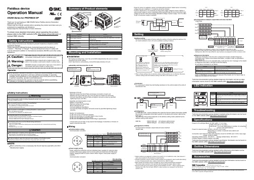
Fieldbus deviceOperation ManualEX250 Series for PROFIBUS DPMounting and InstallationAddress settingBe sure to turn power supply off before setting the switches off before setting the switches of SI unit. Switch installed in cover of SI unit is available for setting of address.InstallationNot having mounting hole, it can’t be set to BUS independently. Be sure to connect manifold to SI unit for setting.And if Input block is unnecessary, connect End plate directly to SI unit.SettingExchange of SI unit•Remove screws from End Plate and release connection of each unit.•Replace old SI unit with new one. (Tie rod does not need to be removed.)•Connect Input Block and End Plate and tighten removed screws by specified tightening torque. (0.6 Nm)Assembly and disconnection of unit Addition of Input Block•Remove screws from End Plate.•Mount attached tie rod.•Connect additional Input Block.•Connect End Plate and tighten removed screws by specified tightening torque. (0.6 Nm)Caution for maintenance(1) Be sure to turn-off all power supplies.(2) Be sure that there is no foreign object in any of units.(3) Be sure that gasket is lined properly.(4) Be sure that tightening torque is according to specification.If these items are not kept, it may lead to the breakage of substrate or intrusion of liquid or dust into the units.LED indicationTroubleshootingTechnical documentation giving detailed troubleshooting information can be found on the SMC website (URL ).SpecificationsPower for SI unit/Input Block: 24 VDC ±20%, 1.1 A or lessInside of SI unit: 0.1 A or lessInput block: 1 A or less (Depending on number of connectingsensors and specifications)Power for solenoid valve: 24 VDC +10%/5%, 2 A or less(Depending on number of solenoid valve station and specifications)Connection load: Solenoid valve with protection circuit for 24 VDC and 1.5 W or less surgevoltage. (made by SMC)Operating ambient temp: -10 to 50 C Storage ambient temp: -20 to 60 C Pollution degree: Pollution degree 3 (UL508)Technical documentation giving detailed specification information can be found on the SMC website (URL ).Outline DimensionsTechnical documentation giving detailed outline dimensions information can befound on the SMC website (URL ).AccessoriesTechnical documentation giving detailed accessories information can be found on the SMC website (URL ).Assembly and disconnection of unitNOTEWhen conformity to UL is necessary the SI unit must be used with a UL1310Class2 power supply.Thank you for purchasing an SMC EX250 Series Fieldbus device (Hereinafter referred to as "SI unit" ).Please read this manual carefully before operating the product and make sure you understand its capabilities and limitations.Please keep this manual handy for future reference.To obtain more detailed information about operating this product,please refer to the SMC website (URL ) or contact SMC directly.These safety instructions are intended to prevent hazardous situations and/or equipment damage.These instructions indicate the level of potential hazard with the labels of"Caution", " Warning" or "Danger". They are all important notes for safety and must be followed in addition to International standards (ISO/IEC) and other safety regulations.OperatorWiringCommunication wiring •Communication connectorM12 5pin reverse (Socket)Example of connected Bus Tee: TURCK VB2/FSW/FKW/FSW45 etc.Power supply wiringPower supply line inside the unit has individual power supplies for solenoid valve actuation (SV power supply) and for Control parts and Input block (SI•SW power supply). Supply 24 VDC for each of them. Either single or dual power supply is available.•Communication connectorM12 5pin (Plug)Example of connected cable: SMC EX500-AP0∗0-S etc.Power for sensor is supplied to sensor connected with Input block. Select sensor concerning voltage drop up to maximum 1 V inside the unit at this moment.If sensor requires 24 V, it is necessary to lower power supply voltage for sensor slightly or secure power supply for sensor separately without going through SI unit so that sensor input voltage can be 24 V with actual loading (allowable voltage of power supply: 19.2 V to 28.8V).gle or dual power supply is available.TerminatorIt is necessary to attach bus terminating resistance to the units located at the ends of transmission line.ConfigurationIn PROFIBUS DP, a device database file called the Generic Station Description (GSD)file provides configuration information specific to the device (ID number, data format,baud rate...).The GSD file of the product depends on the address setting mode (selected by the address setting mode switch).GSD file : SMCA1409.gsd (In hardware setting mode)SMCA1408.gsd (In software setting mode)Assignment of I/O No.Correspondence between output data and valve manifold •Output dataCorrespondence between output data and valve manifold ∗: Each bit of data read into master 4bytes shows ON/OFF of sensor connected to input block.Starting from LSB of first byte (Offset 0), input numbers are assigned to all bits in numeric order.Diagnosis informationDiagnosis information of the SI unit is composed of 6 bytes standard diagnosis information and 7 bytes SI unit status information, 13 bytes in total, as specified in PROFIBUS DP.When the SI unit is in a non-standard state, it will send an error message to the master as diagnosis information, and light up the DIA display.Technical documentation giving detailed diagnosis information and set-up steps information can be found on the SMC website (URL ).Refer to PROFIBUS specifications and manual of the master, etc. for how to refer to diagnosis information on the master.∗: Output numbers are assigned to stations from side D to U of manifold in order. (See manual of each valve manifold for the directions of side D and U)∗: Standard manifold is wired in double. Output numbers are assigned to side A and B alternatively.In case of single solenoid valve, output on side B is free. (Refer to fig.a)∗: Mixed (single and double) wiring is available as long as wiring specifications designate it. This allows output numbers to be specified without having free output. (Refer to fig.b)∗: Each bit of data sent from master (4 bytes) shows ON/OFF (0: OFF, 1: ON) of solenoid valve.Starting from LSB of the first byte (Offset 0), output numbers are assigned to all the bits in numeric order.∗: When software setting mode is selected, address setting switches are not effectual. Moreover,software setting mode and hardware setting mode differ in ID numbers of units.Note: Specifications are subject to change without prior notice and any obligation on the part of the manufacturer.© 2011 SMC Corporation All Rights ReservedAkihabara UDX 15F, 4-14-1, Sotokanda, Chiyoda-ku, Tokyo 101-0021, JAPAN Phone: +81 3-5207-8249 Fax: +81 3-5298-5362URL )(。
西门子SINAMICS G120 CU250S-2 EPOS功能入门指南说明书

01https:///cs/cn/zh/view/109481007C o p y r i g h t S i e m e n s A G C o p y r i g h t y e a r A l l r i g h t s r e s e r v e d目录1 关于入门指南 ....................................................................................................... 32 基本定位功能授权 ................................................................................................ 4 3许可证密钥 ........................................................................................................... 5 3.1 使用“网络许可证管理器”生成许可证密钥 .............................................. 5 3.2 使用“网络许可证管理器”查询已安装的许可证密钥 . (8)4将许可证密钥写入存储卡 ................................................................................... 10 4.1使用 STARTER 输入许可证密钥 ........................................................ 10 4.2 使用 BOP-2 输入许可证密钥 .............................................................. 10 4.3 使用电脑新建KEYS 文件写入 (11)5参考资料 (12)C o p y r i g h t S i e m e n s A G C o p y r i g h t y e a r A l l r i g h t s r e s e r v e d1 关于入门指南在西门子SINAMICS G 系列产品中,G120的CU250S-2控制单元以及G120D 的CU250D-2控制单元支持基本定位功能(EPOS 功能)。
DM使用教程
DM使用教程一、关于“万用版”DM是由ONTRACK公司公司开发的一款老牌的硬盘管理工具,在实际使用中主要用于硬盘的初始化,如低级格式化、分区、高级格式化和系统安装等。
由于功能强劲、安装速度极快而受到用户的喜爱。
但因为各种品牌的硬盘都有其特殊的内部格式,针对不同硬盘开发的DM软件并不能通用,这给用户的使用带来了不便。
DM万用版彻底解除了这种限制,它可以使IBM的DM软件用于任何厂家的硬盘,这对于喜爱该软件的用户来说,无疑是一件令人高兴的事。
DM万用版由两部分组成,一部分就是原来的IBM-DM软件,另一部分则是专门针对该软件开发的一个伙伴程序(DM Partner)。
也就是说,DM万用版其实就是带有伙伴程序的DM,又称之为DM&P(Disk Manager&Partner),如果您有IBM-DM 软件(必须是9.43版),只需将该伙伴程拷入就行了二、主要功能1、提供简易和高级两种安装模式,以满足不同用户的各种要求。
其简易模式适合初级用户使用,高级模式主要针对高级用户而设计。
2、完全支持FA T32文件系统,可以在一个分区上格式化大于2GB的驱动器,当使用高级安装模式时,允许更改硬盘簇的大小。
3、突破8.4GB限制,在安装大于8.4GB的IDE/A TA驱动器时,既可以使用多个FA T12/16分区也可以使用单一可引导的FA T32文件系统分区。
4、提供的硬盘诊断功能可以使您查找硬盘子系统中相互关联的问题。
5、兼容多种操作系统,包括DOS、OS/2、Windows 3.x/95/98和Windows NT。
6、支持IDE电源管理。
7、对IDE/A TA驱动器的多扇区读写支持,加速数据传送。
8、快速格式化IDE/A TA/SCSI驱动器。
绝大多数情况下完全安装驱动器不超过1分钟。
9、支持增强型IDE/Fast A TA的高速数据传送。
10、提供的低级格式化程序比许多BIOS附的Low Level FORMat程序先进得多,甚至可以让某些0磁道出了问题的硬盘起死回生三、安装和运行1、安装用户可以从 ;下载该软件,释放下载文件包后得到IBM-DM.EXE、两个程序使用时先解压缩IBM-DM.EXE(只需在Windows9x中双击执行该文件即可),提示插入软盘时按要求插入,完成后,再将拷入软盘中即完成安装2、运行虽然DM可以在硬盘中运行,但实际使用时,因主要进行硬盘初始化操作,所以还是以软盘运行更为常见。
梅特勒DM系列密度仪操作

密度计计算比重;将 4 0 C (SG4) 或测量温度 (SG) 下水的密度作为参考密度,为此在仪器 中存储了不同温度下的超纯水的密度。
3.2 密度测量原理
s
密度测量基于 U 形玻璃管的电磁感应振动。将一块磁
铁固定到 U 形管上,由振动器引发振动。振动周期 T
由一个传感器测量。
将振动的一整套前后运动称为周期,其耗时为振动周期
3.1 密度
ρ
=
m V
密度 ρ 是参照物的质量 m 与体积 V 的商 (质量密度) [kg / m 3 ] 或 [g / cm 3 ]。 由于密度取决于温度,必须始终一同说明。
SG
=
ρ ρ0
比重 SG (相对密度) 是一种在一定条件下参照物的密度与基准参照物的参照密度 ρ 0 的比值,必须针对两个参照物单独给定条件。
温度 1:
温度 2: 温度 3: 温度 4:
检测器内的电极,直接位于 U 形管表面上方。此温度显示为状态信息 (检测器温度)。
加热块的温度 (结块温度) (该温度不显示)
参比温度 (该温度不显示)
环境温度 (该温度不显示)
下图显示模块大致结构:
操作说明
密度计
DM40 / DM45 Delta Range / DM 50
目录
1 序言 2 密度计说明 3 密度测定基础
4 功能说明
5 设置
3.1 密度 3.2 密度测量原理 3.3 检测器和温度调节器的结构
4.1 4.2 4.3 4.4 4.4.1 4.4.2
终端设备结构 触摸屏操作 主界面 用户界面 在用户界面上输入数据 快捷键
● U盘 ● 外部传感器:
• ErgoSens - 红外线免提传感器,用于自动启动测量 • WasteSens - 废液传感器 • AtmoSens - 大气压力传感器,用于在使用空气进行校正和检验时测量和考虑大气压
DM用户手册
DM 用户手册(中文版)1.0版本目 录1. 安全与维护概述11.1 操作者规范1 1.2 现场操作的安全要求1 1.3 电池使用注意事项1 1.4 设备保养与维护2 1.5 使用注意事项2 1.6 本设备符合的安全规范2 1.7 售后服务32.引言32.1关于手册3 2.2DM系统功能概述3 2.3制定测量计划43. 发射机功能与操作指南5 3.1发射机控制面板53.2屏幕显示内容5 3.3发射机接口5 3.3.1 信号输出线6 3.3.2 AC交流电源线6 3.3.3 连接直流电源线6 3.4 发射机与管道的连接6 3.4.1在CP站(阴极保护站)连接6 3.4.2 无阴极保护站点的管线连接7 3.5选择恰当的频率7 3.6选择输出电流7 3.6.1 确认所选电流档数是否有效输出:7 3.6.2 调节更大的电流输出8 3.7警报8 3.7.1 电压过高8 3.7.2 温度过高8 3.7.3 功率过载84. 接收机的功能与操作94.1接收机9 4.2 液晶显示屏9 4.3按钮10 4.4电池11 4.4.1 内置电池充电 11 4.5用户参数设置 11 4.6频率设置 11 4.7定位模式设置 125. DM 接收机的使用方法 135.1管线定位 13 5.2精确定位 13 5.3读取深度与电流数值 14 5.4存储测量结果 15 5.5电流曲线图 15 5.6 使用A字架查找故障 15 5.6.1 A字架使用方法 15 5.6.2 曲线绘制图表上限设置 16 5.6.3 实时ACVG曲线绘制图及缺陷点定位 16 5.6.4 多故障区(如多孔漆层情况下)A字架的使用 176. 使用外部GPS数据记录仪 176.1兼容GPS与GPS数据记录仪 17 6.2向电脑传输数据 177. 结果分析说明 187.1介绍18 7.2原始错误18 7.2.1 错误操作 18 7.2.2 干扰因素 18 7.3将数据下载至电脑 19 7.4图表解析 208. 性能检测211. 安全与维护概述1.1 操作者规范操作人员在使用前必须接受专业培训1.2 现场操作的安全要求严格遵守公司和管线管理部门的安全规章。
DM使用手册
DM万用版使用手册一、关于“万用版”DM是由ONTRACK公司公司开发的一款老牌的硬盘管理工具,在实际使用中主要用于硬盘的初始化,如低级格式化、分区、高级格式化和系统安装等。
由于功能强劲、安装速度极快而受到用户的喜爱。
但因为各种品牌的硬盘都有其特殊的内部格式,针对不同硬盘开发的DM软件并不能通用,这给用户的使用带来了不便。
DM万用版彻底解除了这种限制,它可以使IBM的DM软件用于任何厂家的硬盘,这对于喜爱该软件的用户来说,无疑是一件令人高兴的事。
DM万用版由两部分组成,一部分就是原来的IBM-DM软件,另一部分则是专门针对该软件开发的一个伙伴程序(DM Partner)。
也就是说,DM万用版其实就是带有伙伴程序的DM,又称之为DM&P (Disk Manager&Partner),如果您有IBM-DM软件(必须是9.43版),只需将该伙伴程序拷入就行了。
二、主要功能1、提供简易和高级两种安装模式,以满足不同用户的各种要求。
其简易模式适合初级用户使用,高级模式主要针对高级用户而设计。
2、完全支持FAT32文件系统,可以在一个分区上格式化大于2GB的驱动器,当使用高级安装模式时,允许更改硬盘簇的大小。
3、突破8.4GB限制,在安装大于8.4GB的IDE/ATA驱动器时,既可以使用多个FAT12/16分区,也可以使用单一可引导的FAT32文件系统分区。
4、提供的硬盘诊断功能可以使您查找硬盘子系统中相互关联的问题。
5、兼容多种操作系统,包括DOS、OS/2、Windows 3.x/95/98和Windows NT。
6、支持IDE电源管理。
7、对IDE/ATA驱动器的多扇区读写支持,加速数据传送。
8、快速格式化IDE/A TA/SCSI驱动器。
绝大多数情况下完全安装驱动器不超过1分钟。
9、支持增强型IDE/Fast ATA的高速数据传送。
10、提供的低级格式化程序比许多BIOS附的Low Level FORMat程序先进得多,甚至可以让某些0磁道出了问题的硬盘起死回生三、安装和运行1、安装用户可以从 下载该软件,释放下载文件包后得到IBM-DM.EXE、两个程序,使用时先解压缩IBM-DM.EXE(只需在Windows9x中双击执行该文件即可),提示插入软盘时按要求插入,完成后,再将拷入软盘中即完成安装2、运行虽然DM可以在硬盘中运行,但实际使用时,因主要进行硬盘初始化操作,所以还是以软盘运行更为常见。
EX250系列CANopen字段总线设备操作手册说明书
Fieldbus deviceOperation ManualEX250 Series for CANopenMounting and InstallationInstallationThe SI unit does not have mounting holes, so it cannot be installed alone. Make sure to connect the solenoid valve. When an input block is not required, connect the end plate directly to the SI unit.SettingExchange of SI unit•Remove screws from End Plate and release connection of each unit.•Replace old SI unit with new one. (Tie rod does not need to be removed.)•Connect Input Block and End Plate and tighten removed screws by specified tightening torque. (0.6 Nm)Assembly and disconnection of unit Addition of Input Block•Remove screws from End Plate.•Mount attached tie rod.•Connect additional Input Block.•Connect End Plate and tighten removed screws by specified tightening torque. (0.6 Nm)Caution for maintenance(1) Be sure to turn-off all power supplies.(2) Be sure that there is no foreign object in any of units.(3) Be sure that gasket is lined properly.(4) Be sure that tightening torque is according to specification.If these items are not kept, it may lead to the breakage of substrate or intrusion of liquid or dust into the units.TroubleshootingTechnical documentation giving detailed troubleshooting information can be found on the SMC website (URL ).SpecificationsPower for CANopen communication: 18 to 30 VDC, 0.1 A or lessPower for input block: 24 VDC ±20%, 1 A or less (Depending on number of connectingsensors and specifications)Power for solenoid valve: 24 VDC +10%/-5%, 2 A or less(Depending on number of solenoid valve station and specifications)Connection load: Solenoid valve with protection circuit for 24 VDC and 1.5 W or less surgevoltage. (made by SMC)Operating ambient temp: -10 to 50 C Storage ambient temp: -20 to 60 C Pollution degree: Pollution degree 3 (UL508)Technical documentation giving detailed specification information can be found on the SMC website (URL ).Outline DimensionsTechnical documentation giving detailed outline dimensions information can be found on the SMC website (URL ).Assembly and disassembly of the SI unitNOTEWhen conformity to UL is necessary the SI unit must be used with a UL1310Class2 power supply.Thank you for purchasing an SMC EX250 Series Fieldbus device (Hereinafter referred to as "SI unit" ).Please read this manual carefully before operating the product and make sure you understand its capabilities and limitations.Please keep this manual handy for future reference.To obtain more detailed information about operating this product,please refer to the SMC website (URL ) or contact SMC directly.These safety instructions are intended to prevent hazardous situations and/or equipment damage.These instructions indicate the level of potential hazard with the labels of"Caution", " Warning" or "Danger". They are all important notes for safety and must be followed in addition to International standards (ISO/IEC) and other safety regulations.OperatorWiringCommunication wiringSW power is supplied to the sensor connected to the input block. There is a voltage drop up to maximum 1 V inside the SI unit when SW power is supplied. Select a sensor taking this voltage drop into consideration. If 24 V must be supplied to the sensor, it is necessary toincrease the SW power supply voltage so that the input voltage of the sensor will be 24 V with the actual load. (Allowable SW power supply range: 19.2 V to 28.8 V)Bus cable and termination resistorsThe cables, connectors, and termination resistors used in CANopen networks shall meet the requirements defined in ISO 11898. In addition, here are given some guidelines for selecting cables and connectors.The table below shows some standard values for DC parameters for CANopen networks with less than 64 nodes.Switch settingBefore setting of Node-ID by DIP switch, turn “OFF” power supply to the SI unit.Output No. assignmentCombinations of output data and valve manifoldNote: Specifications are subject to change without prior notice and any obligation on the part of the manufacturer.© 2011 SMC Corporation All Rights ReservedtkihabaraMUwXMdhy]Mg_dg_d]MSotokanda]Mvhiyoda_ku]MTokyoMdcd_cced]M±tPt−PhonemM[kdMf_hecj_keglMMMyaxmM[kdMf_helk_hfieUR“Mhttpmbbwwwasmcworldacom∗: Output numbers are assigned to stations from side D to U of manifold in order. (See manual of each valve manifold for the directions of side D and U).∗: Standard manifold is wired in double. Output numbers are assigned to side A and B alternatively.In case of single solenoid valve, output on side B is free. (Refer to fig.a)∗: Mixed (single and double) wiring is available as long as wiring specifications designate it. This allows output numbers to be specified without having free output. (Refer to fig.b)∗: Each bit of data sent from master (4 bytes) shows ON/OFF (0: OFF, 1: ON) of solenoid valve.Starting from LSB of the first byte (Offset0), output numbers are assigned to all the bits in numeric order.Input No. assignmentThe inputs of the Input block are assigned from the SI unit side Input block in the order 0,1,2…maximum of 31.AccessoriesTechnical documentation giving detailed accessories information can be found on the SMC website (URL ).Communication wiringRelation Baud rate and Bus length are as follows.Power supply wiringLED indicationFE connectionConnect the ground terminal to the ground. Resistance to the ground should be 100 Ωor less.For drop cables a wire cross-section of 0.25 to 0.34 mm would be an appropriate choice in many cases.Besides the cable resistance, there should also be considered the real resistance of the connectors, if calculating the voltage drop. The read resistance of one connector should be in the range of 2.5 to 10 mΩ.。
leica DM500 DM500 B 说明书
Leica DM500,DM500 B 操作手册内容提要安全性规定 4 Leica DM500,DM500 B 15准备开始! 18开始设置! 25开始! 34显微镜保养 36尺寸 39目录安全性规定 4安全概念 5这本操作手册中所用的符号 6重要提示 7使用说明 8健康风险和使用安全 10仪器负责人须知 11保养说明 12附件、维护和维修 13电气数据和环境条件 14 Leica DM500,DM500 B 15祝词! 16拆箱 17准备开始! 18连接观察镜筒 19Leica EZ 观察镜筒 – 集成目镜 20徕卡标准观察镜筒 – 独立目镜 22防护眼罩 23安装物镜和显微镜台下聚光器 24开始设置! 25开启显微镜 26使用聚光器 27准备观察样本载玻片 28聚焦 29观察镜筒调节 30油浸技术 32开始! 34准备!设置!开始! 35显微镜保养 36常规维护 37尺寸 39安全性规定安全概念Leica DM 显微镜系列的各个模块都带有一张包含所有相关用户手册的交互式 CD 光盘 (具有多种语言版本)。
请将其放在安全且便于取用的地方。
也可以从我们的网站下载和打印用户手册和更新:.本操作手册描述了 Leica DM 显微镜系列中各个模块的特殊功能,并包含有关其操作安全、维护及附件的重要说明。
“安全概念”册子包含了有关显微镜、附件与电气附件的维修工作、要求与操作的附加安全信息,以及常规的安全说明。
可以将各个系统的部件与外部供应商提供的相关部件结合起来使用。
请阅读本用户手册和供应商提供的安全要求。
在安装、操作或使用仪器之前,请先阅读上述用户手册。
尤其是要仔细阅读所有安全说明。
为了使仪器保持其原始状态,并确保操作安全,用户必须遵守上述用户手册中的说明和警告。
这本操作手册中所用的符号危险警告• 此符号表示特别重要的信息,必须仔细阅读并严格遵守。
否则可能会导致以下后果:Ϙ人身伤害Ϙ功能性故障或仪器损坏危险电压警告此符号表示必须阅读和遵守的非常重要的信息。