变电站综合自动化英文文献
变电站外文翻译外文文献英文文献变电站的综合概述(工程科技)
附录Ⅲ英文翻译A comprehensive overview of substationsAlong with the economic development and the modern industry developments of quick rising, the design of the power supply system become more and more completely and system. Because the quickly increase electricity of factories, it also increases seriously to the dependable index of the economic condition, power supply in quantity. Therefore they need the higher and more perfect request to the power supply. Whether Design reasonable, not only affect directly the base investment and circulate the expenses with have the metal depletion in colour metal, but also will reflect the dependable in power supply and the safe in many facts. In a word, it is close with the economic performance and the safety of the people. The substation is an importance part of the electric power system, it is consisted of the electric appliances equipments and the Transmission and the Distribution. It obtains the electric power from the electric power system, through its function of transformation and assign, transport and safety. Then transport the power to every place with safe, dependable, and economical. As an important part of power’s transport and control, the transformer substation must change the mode of the traditional design and control, then can adapt to the modern electric power system, the development of modern industry and the of trend of the society life.Electric power industry is one of the foundations of national industry and national economic development to industry, it is a coal, oil, natural gas, hydropower, nuclear power, wind power and other energy conversion into electrical energy of the secondary energy industry, it for the other departments of the national economy fast and stable development of the provision of adequate power, and its level of development is a reflection of the country's economic development an important indicator of the level. As the power in the industry and the importance of the national economy, electricity transmission and distribution of electric energy used in these areas is an indispensable component.。
有关变电所设计的外文文献
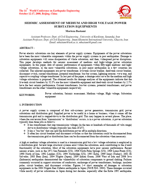
SEISMIC ASSESSMENT OF MEDIUM AND HIGH VOLTAGE POWERSUBSTATION EQUIPMENTSMorteza BastamiAssistant Professor, Dept. of Civil Engineering , University of Kurdistan, Sanandaj, Iran Assistant Professor, Dept. of Civil Engineering , Imam Khomeini International University, Ghazvin, IranEmail: mbastami@uok.ac.ir, mbastami@ABSTRACT :Power electric substations are key elements of power supply systems. Equipments of the power substations have been the most vulnerable components within the power supply systems in past earthquakes. Damage to substation equipments will cause disoperation of whole substation, and then, widespread power disruptions. This paper develops methods for seismic assessment of medium- and high-voltage power substation equipments. In this paper, data of seismic performance of equipments within fifty-eight medium- and high-voltage substations, as the most vulnerable substations, in past major earthquakes in a few countries are collected. The selected equipments are power transformer, live-tank circuit breaker, dead-tank circuit breaker, disconnect switch, current transformer, potential transformer, bus-bar system, lightning arrester, wave trap, and capacitive coupling voltage transformer. In last part of the paper, a damage ratio curve for the medium and high voltage substations is proposed. The obtained results for damage analyses of the equipments indicate that the live-tank circuit breakers by 32.3% are the most vulnerable equipment and dead-tank circuit breakers by 2.5% have the best seismic performance. Current transformers, bus-bar systems, potential transformers, and power transformers are the other vulnerable equipments respectively.KEYWORDS:Power substation, Seismic assessment, Medium voltage, High voltage, Substation equipment1. INTRODUCTIONA power supply system is composed of four sub-systems:power generators, transmission grid, power substations and distribution grid. Supplied power to be useful in a home or business, when it comes off the transmission grid and is stepped-down to the distribution grid. This may happen in several phases. The place, where the conversion from "transmission" to "distribution" occurs, is in a power substation. A power substation typically does three jobs as follows:It has transformers that step transmission voltages (in the tens or hundreds of thousands of volts range) down to distribution voltages (typically less than 20 kV).It has a "bus-bar" that can split the distribution power off in multiple directions.It often has circuit breakers and disconnect switches so that the substation could be disconnected from the transmission grid or distribution lines can be disconnected from the substation when necessary.A high or medium voltage substation is used in a transmission grid but a low voltage substation is employed in a distribution grid. Several large structural systems exist within the substation, each contributing to the overall functionality of the substation. Most of the substation equipments have poor seismic performance. Recent seismic events, such as the 1971 San Fernando (US), 1986 North Palm Springs (US), 1989 Loma Prieta (US), 1990 North of Iran, 1992 Landers (US), 1994 Northridge (US), 1995 Kobe, 1999 Izmit (Turkey), 2001 El Salvador, 2003 Bam (Iran), 2004 Niigata (Japan), 2004 Indian Ocean, 2006 West of Iran and 2006 Java (Indonesia) earthquakes demonstrated the vulnerability of substation components to ground shaking. Failures commonly occurred in support structures of conductors, anchorage of power transformers, bushings, insulator poles, circuit breakers, and disconnect switches. Figures 1-4 show examples of damages to substation equipments in the 2004 Niigata Ken Chūetsu earthquake in Japan (JSCE/JGS, 2004). These damages occurred while mostly of power substations in Japan during last decades, especially after the Kobe 1995 earthquake,have been strengthened against earthquake. Japan Electric Association in 1985, for first time, developed a Guideline titled as “Earthquake resistant design guideline for electric facilities in power substation”, which was revised in 1999 (JEAG 5003-1999).Power substations based on functionality are classified in three types as follows:•Transmission substations (voltage and current increase or decrease)•Distribution substations (voltage decrease and current increase)•Switchyards (no change in voltage and current)Also based on voltage level they are categorized in three class, which are:•Low-voltage: less than 150 kV•Medium-voltage: between 150 kV and 350 kV•High-voltage: 350 kV and aboveIn this paper, seismic performance of medium- and high-voltage power substation equipments are discussed.Figure 1 Lightning arresters of all three- Figure 2 Oil leakage from joint betweenphases were broken in Nagaoka Sub. transformer and condenser in Minami Nagaoka Sub.(JSCE, 2004) (JSCE, 2004)Figure 3 Failure of condenser in Nagaoka sub. Figure 4 Extrusion of gasket and oil leakage(JSCE, 2004) in bushing of 154 kV transformer in Uonuma Sub.(JSCE, 2004)2. DATA GATHERINGIn this research, at first damages to the power systems in 43 earthquakes, from the 1923 Kanto earthquake(Japan) to the 2006 Java earthquake(Indonesia)are investigated, which hundreds of power substations had been suffered damage. Unfortunately exact information like as ground acceleration at substation site, description of damages, exact number of damaged equipments, voltage level of equipments and etc. in mostly of reports are not reported. Due to these data limitations, just enough data of 58 medium- and high-voltage substations (as the most vulnerable substations) are found, which are used in this paper. Due to volume consuming of this paper, it is not possible to list all specifications of these substations and also all references which are more than 80 references but it could be referred to Chapter 2 of (Bastami, 2007) to view list the mostly of the references. Operation of a power substation is function of equipments operation within the substation such as power transformer, disconnect switch, live-tank circuit breaker, current transformer, bus-bar and etc. A substation, based on its functionality, may include some or all the equipments. All important equipments within a standard substation are listed below:¾Power transformer¾Live-tank circuit breaker¾Dead-tank circuit breaker¾Disconnect switches¾Current transformer¾Potential transformer¾Bus-bar system¾Lightning arrester¾Wave trap¾Capacitive coupling voltage transformerIn this research all the above equipments are taken into account.3. PERFORMANCE OF SUBSTATION EQUIPMENTS IN PAST EARTHQUAKES3.1Performance of EquipmentsIn this section, results for seismic performance of the abovementioned equipments are presented. Percentage of damage for each equipment is defined as ratio of number of damaged equipments to total number of that equipment. Figures 5-14 depict percentage of damaged equipments in medium- and high-voltage substations respectively. The figures indicate vulnerability of all equipments within medium- or high-voltage power substations.Figure 5 Percentage of damaged power transformers in medium- and high-voltage substationsFigure 6 Percentage of damaged live-tank circuit breakers in medium- and high- voltage substationsFigure 7 Percentage of damaged dead-tank circuit breakers in medium- and high- voltage substationsFigure 8 Percentage of damaged disconnect switches in medium- and high- voltage substationsFigure 9 Percentage of damaged current transformers in medium- and high-voltage substationsFigure 10 Percentage of damaged potential transformers in medium- and high-voltage substationsFigure 11 Percentage of damaged bus-bar systems in medium- and high-voltage substationsFigure 12 Percentage of damaged lightning arresters in medium- and high-voltage substationsFigure 13 Percentage of damaged wave traps in medium- and high-voltage substationsFigure 14 Percentage of damaged capacitive coupling voltage transformer in medium- and high-voltagesubstationsTable 1 shows total number, number of the damaged and undamaged equipments, in which disconnect switches by 429 cases, live-tank circuit breakers by 150 cases and power transformers by 90 cases, bus-bar systems by 83 cases, lightning arresters by 81 cases and current transformers by 78 cases are damaged repeatedly in the 58 studied substations in past earthquakes. Table 1 also depicts percentage of damaged substation equipments, which indicates live-tank circuit breakers by 32.3% are the most vulnerable equipment and dead-tank circuit breakers by 2.5% have the best seismic performance. Current transformers, bus-bar systems, potential transformers and power transformers are the other vulnerable equipments. An interesting point is that disconnect switches by maximum reported number of damages, has better performance in comparison with live-tank circuit breakers, current transformers, bus-bar systems, potential transformers and power transformers.Table 1 Performance of the 58 medium- and high-voltage substation equipments in past earthquakesNo. Equipment TotalnumberDamagednumberUndamagednumberAverage ofpercentageof damage1 PowerTransformer 351 90 261 25.6% 2 Live-tankCircuitBreaker 464 150 314 32.3% 3 Dead-tankCircuitBreaker1133 28 1105 2.5% 4 DisconnectSwitch 3376 429 2947 12.7% 5 CurrentTransformer 250 78 172 31.2% 6 PotentialTransformer 89 23 66 25.8% 7 Bus-barSystem 261 83 178 31.8% 8 LightningArrester 540 81 459 15.0% 9 WaveTrap 114 27 87 23.7%10 Capacitive Coupling VoltageTransformer142 17 125 12.0%3.1Damage Ratio Curve of Medium and High Voltage SubstationsIn this section, a damage ratio curve for the medium and high voltage substations is proposed, which is shown in Figure 15. The curve is a bilinear curve, which is divided in two parts: first part is for PGA less than 0.55g and second part belongs to PGA more than 0.55g. For PGA equal to 0.55g, damage ratio is approximately estimated 0.28 and maximum damage ratio is approximately estimated 0.4 for PGA more than 1.1g.4. CONCLUSIONSThis paper seeks physical performance of power supply systems in past earthquakes. Damages to the power systems in 43 earthquakes, from the 1923 Kanto Earthquake until the 2006 Java Earthquake are studied. The selected earthquakes have proven widespread vulnerability of power system equipments from different points of view. Obtained results are summarized as follows:1- Damage to porcelain units of high- and medium-voltage substation equipment has been a recurring problem. Equipment operating at low voltages performs well when good seismic installation practices of anchorage and conductor interconnection flexibility are followed. Some types of equipment, which operating at voltages of 220 kV and above, are vulnerable. Generally, we can say: the higher operating voltage, the more vulnerable equipment.2- The highest voltage equipment, which is subjected to earthquake, is 500 kV.3- In medium and high-voltage substations, several types of failures are frequently observed. Inadequately anchored rail-supported transformers have fallen from their elevated platforms and have been severely damaged. Leaking or broken bushings are common.0.10.20.30.40.50.60.70.80.9100.10.20.30.40.50.60.70.80.91 1.1 1.2PGA(g)D a m a g e R a t i oFigure 15 Damage ratio curve of the medium and high voltage substations4- Design of some equipments appear to be inherently vulnerable, while other equipment that serves thesame function and operates at the same voltage can be quite rugged; for example, some live-tank circuit breakers versus dead-tank circuit breakers.5- Damage ratio curve of the medium and high voltage substations based on the 58 studied substationsis developed, which could be useful for engineers in practical purposes.ACKNOWLEDGMENTThe author wish to thank Professor Yasuko Kuwata from Kobe University for giving valuable data of the 2004Niigata Chuetsu Earthquake.REFERENCESBastami, Morteza (2007). Seismic Reliability of Power Supply System Based on Probabilistic Approach. Ph.D thesis, Kobe University, Japan.Japan Electric Association Guideline, (1999). Earthquake Resistant Design Guideline for Electric Facilities in Power Substation. JEAG 5003-1999, Japan, (in Japanese).JSCE/JGS mission on the 2004 Niigata Chuetsu earthquake (2004). Reconnaissance report on the 2004 Niigata Chuetsu Earthquake (ver1.0), Chapter 9.4 Power supply system (9pages) Available at http://shake.iis.u-tokyo.ac.jp/chuetsu/9-4.pdf (in Japanese).SEISMIC ASSESSMENT OF MEDIUM AND HIGH VOLTAGE POWER SUBSTATION EQUIPMENTS作者:Morteza Bastami作者单位:Assistant Professor, Dept. of Civil Engineering , University of Kurdistan, Sanandaj, Iran Assistant Professor, Dept. of Civil Engineering , Imam Khomeini International University,Ghazvin, Iran本文链接:/Conference_WFHYXW278686.aspx。
一般变电站建设的外文文献(优选.)

最新文件---------------- 仅供参考--------------------已改成-----------word文本 --------------------- 方便更改General Requirements to Construction of SubstationSubstations are a vital element in a power supply system of industrial enterprises.They serve to receive ,convert and distribute electric energy .Depending on power and purpose ,the substations are divided into central distribution substations for a voltage of 110-500kV;main step-down substations for110-220/6-10-35kV;deep entrance substations for 110-330/6-10Kv;distribution substations for 6-10Kv;shop transformer substations for 6-10/0.38-0.66kV.At the main step-down substations, the energy received from the power source is transformed from 110-220kV usually to 6-10kV(sometimes 35kV) which is distributed among substations of the enterprise and is fed to high-voltage services.Central distribution substations receive energy from power systems and distribute it (without or with partial transformation) via aerial and cable lines of deep entrances at a voltage of 110-220kV over the enterprise territory .Central distribution substation differs from the main distribution substation in a higher power and in that bulk of its power is at a voltage of 110-220kV;it features simplified switching circuits at primary voltage; it is fed from the power to an individual object or region .Low-and medium-power shop substations transform energy from 6-10kV to a secondary voltage of 380/220 or 660/380.Step-up transformer substations are used at power plants for transformation of energy produced by the generators to a higher voltage which decreases losses at a long-distance transmission .Converter substations are intended to convert AC to DC (sometimes vice versa) and to convert energy of one frequency to another .Converter substations with semiconductor rectifiers are convert energy of one frequency to another .Converter substations with semiconductor rectifiers are most economic. Distribution substations for 6-10kV are fed primarily from main distribution substations (sometimes from central distribution substations).With a system of dividing substations for 110-220kV, the functions of a switch-gear are accomplished by switch-gears for 6-10kV at deep entrance substations.Depending on location of substations their switch-gear may be outdoor or indoor. The feed and output lines at 6-10kV substations are mainly of the cable type .at 35-220kV substations of the aerial type .When erecting and wiring the substations ,major attention is given to reliable and economic power supply of a given production.Substations are erected by industrial methods with the use of large blocks and assemblies prepared at the site shops of electric engineering organizations and factories of electrical engineering industry .Substations are usually designed for operation without continuous attendance of the duty personnel but with the use of elementary automatic and signaling devices.When constructing the structural part of a substation .it is advisable to use light-weight industrial structures and elements (panels ,floors ,etc.) made of bent sections .These elements are pre-made outside the erection zone and are only assembled at site .This considerably cuts the terms and cost of construction.Basic circuitry concepts of substations are chosen when designing a powersupply system of the enterprise .Substations feature primary voltage entrances .transformers and output cable lines or current conductors of secondary voltage .Substations are mounted from equipment and elements described below .The number of possible combinations of equipment and elements is very great .Whenelaborating a substation circuitry ,it is necessary to strive for maximum simplification and minimizing the number of switching devices .Such substations are more reliable and economic .Circuitry is simplified by using automatic reclosure or automatic change over to reserve facility which allows rapid and faultless redundancy of individual elements and using equipment.When designing transformer substations of industrial enterprises for all voltages , the following basic considerations are taken into account:1. Preferable employment of a single-bus system with using two-bus systems only to ensure a reliable and economic power supply;2. Wide use of unitized constructions and busless substations;3.Substantiated employment of automatics and telemetry ;if the substation design does not envisage the use of automatics or telemetry ,the circuitry is soarranged as to allow for adding such equipment in future without excessive investments and re-work.e of simple and cheap devices-isolating switches ,short-circuiting switches ,load-breaking isolators ,fuses ,with due regard for their switching capacity may drastically cut the need for expensive and critical oil ,vacuum ,solenoid and air switches .Substation and switch-gear circuitries are so made that using the equipment of each production line is fed from individual transformers ,assemblies ,the lines to allow their disconnection simultaneously with mechanisms without disrupting operation of adjacent production flows.When elaborating circuitry of a substation, the most vital task is to properly choose and arrange switching devices(switches ,isolators ,current limiters ,arresters ,high-voltage fuses).The decision depends on the purpose ,power and significance of the substation.Many years ago, scientists had very vague ideas about electricity. Many of them thought of it as a sort of fluid that flowed through wires as water flows through pipes, but they could not understand what made it flow. Many of them felt that electricity was made up of tiny particles of some kind ,but trying to separate electricity into individual particles baffled them.Then, the great American scientist Millikan, in 1909,astounded the scientific world by actually weighing a single particle of electricity and calculating its electric charge. This was probably one of the most delicate weighing jobs ever done by man,for a single electric particle weighs only about half of a millionth of a pound. To make up a pound it would take more of those particles than there are drops of water in the Atlantic Ocean.They are no strangers to us, these electric particles, for we know them as electrons. When large numbers of electrons break away from their atoms and move through a wire,we describe this action by saying that electricity is flowing through the wire.Yes,the electrical fluid that early scientists talked about is nothing more than electrical flowing along a wire.But how can individual electrons be made to break away from atoms? And how can these free electrons be made to along a wire? The answer to the first questionlies in the structure of the atoms themselves. Some atoms are so constructed that they lose electrons easily. An atom of copper, for example ,is continually losing an electron, regaining it(or another electron),and losing it again. A copper atom normally has 29 electrons, arranged in four different orbits about its nucleus. The inside orbit has 2 electrons. The next larger orbit has 8.The third orbit is packed with 18 electrons . And the outside orbit has only one electron.It is this outside electron that the copper atom is continually losing, for it is not very closely tied to the atom. It wanders off, is replaced by another free-roving electron, and then this second electron also wanders away.Consequently,in a copper wire free electrons are floating around in all directions among the copper atoms.Thus, even through the copper wire looks quite motionless to your ordinary eye, there is a great deal of activity going on inside it. If the wire were carrying electricity to an electric light or to some other electrical device, the electrons would not be moving around at random. Instead, many of them would be rushing in the same direction-from one end of the wire to the other.This brings us to the second question .How can free electrons be made to move along a wire? Well ,men have found several ways to do that .One way is chemical. Volta,s voltaic pile,or battery, is a chemical device that makes electricity(or electrons)flow in wires. Another way is magnetic. Faraday and Henry discovered how magnets could be used to make electricity flow in a wire.MagnetsAlmost everyone has seen horseshoe magnets-so called because they are shaped like horseshoes. Probably you have experimented with a magnet, and noticed how it will pick up tacks and nails, or other small iron objects. Men have known about magnets for thousands of years.Several thousand years ago, according to legend, a shepherd named Magnes lived on the island of Crete, in the Mediterranean Sea .He had a shepherds crook tipped with iron. One day he found an oddly shaped black stone that stuck to this iron ter, when many other such stones were found, they were called magnets(after Magnets).These were natural magnets.In recent times men have learned how to make magnets out of iron. Moreimportant still, they have discovered how to use magnets to push electrons through wires-that is, how to make electricity flow. Before we discuss this, there arecertain characteristics of magnets that we should know about.If a piece of glass is laid on top of a horse- shoes magnet, and if iron filings are then sprink ledon the glass, the filings will arrange themselves into lines. If this same thing is trid with a bar magnet(a horseshoe magnet straightened out),the lines can be seen more easily. These experiments demonstrate what scientists call magnetic lines of force. Magnets, they explain, work through lines of force that ext- end between the two ends of the magnet. But electrons seem to have magnetic lines of force around them, too.This can be proved by sticking a wire through a piece ofcard board, sprinkling iron filings on the cardboard, and connecting a battery to the wire. The filings will tend to form rings around the wire,as a result of the magnetism of the moving electrons(or electricity).So we can see that there is arelationship between moving electrons and magnetism, Magnetism results from the movement of electrons.Of course, electrons are not really flowing in the bar magnet, but they are in motion, circling the nuclei of the iron atoms. However, in the magnet, circling thelined up in such a way that their electrons are circling in the same direction. Perhaps a good comparison might be a great number of boys whirling balls onstrings in a clockwise direction around their heads.——The Trend Of Integrated Substation Automation Technology Development最新文件---------------- 仅供参考--------------------已改成-----------word文本 --------------------- 方便更改赠人玫瑰,手留余香。
变电站设计英文参考文献
变电站设计英文参考文献以下是关于变电站设计的英文参考文献列表及简介:1. "Modern Power Station Practice Vol 1: Electrical Systems and Equipment" by Central Electricity Generating Board (CEGB) - 这本书是关于电站设计的权威参考书之一,其中包含了变电站设计的细节和要求。
2. "HVDC Transmission: Power Conversion Applications in Power Systems" by K.R. Padiyar - 这本书主要涉及高压直流输电的理论和应用,而变电站通常是将交流电转换成直流电进行输电的一部分,因此这本书可以帮助设计师更好地理解变电站的工作原理。
3. "Electric Power Substations Engineering" by John D. McDonald- 这本书是变电站设计和工程的综合指南,包含了变电站的各个方面,从概述到详细设计,以及施工和运行。
4. "Transformer and Inductor Design Handbook" by Colonel Wm. T. McLyman - 压变和电感器是变电站中常见的元件,因此设计师需要了解它们的设计和制造,这本书提供了详细的指导和案例。
5. "Electric Power Distribution Handbook" by Thomas Allen Short- 这本书提供了关于配电系统的基础知识和设计方法,这对于变电站设计师来说也非常重要,因为变电站通常是配电网络的一个关键组成部分。
6. "Switchgear and Protection" by J.B Gupta - 变电站中使用的开关设备和保护系统非常关键,这本书提供了涵盖相关主题的详细信息,包括故障和过电压保护,以及开关设备的选择和维护。
变电站设计英文参考文献

变电站设计英文参考文献# Design of SubstationSubstations play a vital role in the power system infrastructure, serving as the main junction point for the transmission and distribution of electrical energy. The design of substations requires careful consideration of various factors to ensure safe and efficient power transfer. This article provides an overview of the design considerations involved in the planning and construction of a substation.## Site SelectionThe first step in substation design is to identify an appropriate location. The site must be strategically chosen, considering factors such as proximity to power sources, accessibility, land availability, and environmental impacts. Adequate land area is required to accommodate the equipment, structures, and necessary safety clearances.## Electrical System AnalysisOnce the site is finalized, an electrical system analysis is conducted to determine the voltage level, load capacity, and other electrical parameters. This analysis helps in determining the type and rating of transformers, circuit breakers, and other equipment required for the substation.## Substation LayoutThe layout of the substation depends on several factors, including the configuration of the electrical system and available land area. The layout should be designed to allow for efficient power flow, adequate spacing between equipment, and clear access for maintenance and operation. Different areas for high voltage, medium voltage, and low voltage equipment are designated within the substation.## Equipment SelectionCareful selection of equipment is crucial for a well-functioning substation. Transformers, circuit breakers, switchgear, protection relays, and control systems are some of the essential components. The equipment should be reliable, efficient, and compatible with the electrical system requirements. Factors such as load capacity, fault current ratings, and safety features are considered during equipment selection.## Safety ConsiderationsSafety is of utmost importance in substation design. Adequate safety measures should be implemented to protect personnel and equipment. Safety clearances, grounding systems, fire suppression systems, and protective barriers are some of the key considerations. Compliance with relevant codes, standards, and regulations is essential for ensuring a safe working environment.## Environmental ImpactThe environmental impact of a substation should be minimized. Measures such as proper disposal of waste materials, noise reduction, and landscaping are undertaken to mitigate the impact on the surrounding ecosystem and nearby communities. Environmental regulations and guidelines must be followed throughout the design and construction process.## Construction and CommissioningOnce the design is finalized, the construction phase begins. The construction process involves civil works, installation of equipment, wiring, and testing. The commissioning phase includes the initial energization, functional testing, and synchronization with the power grid. Proper coordination between various stakeholders, including engineers, contractors, and utility companies, is crucial for a successful construction and commissioning process.## Maintenance and UpgradesRegular maintenance and upgrades are essential for the efficient operation of a substation throughout its lifespan. Periodic inspections, equipment testing, and preventivemaintenance help ensure the reliability and safety of the substation. Upgrades may be required to accommodate future growth, technological advancements, or changes in the electrical system.In conclusion, the design of a substation involves several critical considerations, including site selection, electrical system analysis, layout design, equipment selection, safety measures, environmental impact, and construction and commissioning processes.A well-designed and properly maintained substation is vital for the reliable and uninterrupted transmission and distribution of electrical energy.。
电力专业英语5--变电站综合自动化

45-10
• Convert the traditional switchboard look to a graphical user interface (GUI) accessible through the station PC.
• 将传统的操作盘转换为可以通过站控计算机操作 的图形交互接口
可以远方实现站内功能和操作的监视和控制。可通过 高速通信信道或光纤实现站间及与调度的通信
45-9
• Use microprocessor-based relays to perform online monitoring and control operations.
• 使用数字式保护(或称为微机保护)实现 监视和控制 • Digital protection
• 功能:
变压器保护,母线保护,线路(出线)保护 站控设备,表计,显示 SCADA
45-5
去示
变电站照片 主控室照片
经测量装置测量
45-6
45-7
PowerWorld Visualization in 40,000 MW TVA Control Room
45-8
Definition of Substation Automation
GPS Process level
Data Acquisition A DIKO 6800
Dual configuration
Optic fiber
IED DIKO 6100
110kV substation
IED DIKO 6100
IED DIKO 6100
IED DIKO 6100
IED DIKO 6100
电力专业英语
电气工程学院
(完整word版)关于变配电的英文文献1
On architectural design of electrical energy saving methods Abstract : In this paper the architectural design of electrical energy saving, energy—saving methods, from the choice of transformer capacity, power factor compensation, lighting dimmers equipment, motor starter equipment selection, Electrical Design exposition of several energy—saving methods.Keywords : loss of electrical energy saving transformer power factor VVVF lighting energy saving soft starter ,as a result of population increase , industrial development, the improvement of living standards, the consumption of energy has increased dramatically, the energy crisis was imminent.Therefore, the businesses of the energy—saving requirements, secondary energy conservation -- Energy, civil construction, it has become the focus of electrical design。
变电站电气一次设计外文文献
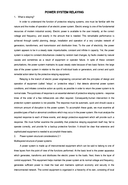
POWER SYSTEM RELAYING1、What is relaying?In order to understand the function of protective relaying systems, one must be familiar with the nature and the modes of operation of an electric power system. Electric energy is one of the fundamental resources of modem industrial society. Electric power is available to the user instantly, at the correct voltage and frequency, and exactly in the amount that is needed. This remarkable performance is achieved through careful planning, design, installation and operation of a very complex network of generators, transformers, and transmission and distribution lines. To the user of electricity, the power system appears to be in a steady state: imperturbable, constant and infinite in capacity. Yet, the power system is subject to constant disturbances created by random load changes, by faults created by natural causes and sometimes as a result of equipment or operator failure. In spite of these constant perturbations, the power system maintains its quasi steady state because of two basic factors: the large size of the power system in relation to the size of individual loads or generators, and correct and quick remedial action taken by the protective relaying equipment.Relaying is the branch of electric power engineering concerned with the principles of design and operation of equipment (called “relays’or ‘protective relays’)that detects abnormal power system conditions, and initiates corrective action as quickly as possible in order to return the power system to its normal state. The quickness of response is an essential element of protective relaying systems - response times of the order of a few milliseconds are often required. Consequently,human intervention in the protection system operation is not possible. The response must be automatic, quick and should cause a minimum amount of disruption to the power system. To accomplish these goals, we must examine all possible types of fault or abnormal conditions which may occur in the power system. We must analyze the required response to each of these events, and design protective equipment which will provide such a response. We must further examine the possibility that protective relaying equipment itself may fail to operate correctly, and provide for a backup protective function. It should be clear that extensive and sophisticated equipment is needed to accomplish these tasks.2、Power system structural considerations 2.1Multilayered structure of power systemsA power system is made up of interconnected equipment which can be said to belong to one of three layers from the point of view of the functions performed. At the basic level is the power apparatus which generates, transforms and distributes the electric power to the loads. Next, there is the layer of control equipment. This equipment helps maintain the power system at its normal voltage and frequency, generates sufficient power to meet the load and maintains optimum economy and security in the interconnected network. The control equipment is organized in a hierarchy of its own, consisting of localand central control functions. Finally, there is the protection equipment layer. The response time of protection functions is generally faster than that of the control functions. Protection acts to open and close circuit breakers, thus changing the structure of the power system, whereas the control functions act continuously to adjust system variables, such as the voltages, currents and power flow on the network. Oftentimes, the distinction between a control function and a protection function becomes blurred. This is becoming even more of a problem with the recent advent of computer-based protection systems in substations. For our purposes, we may arbitrarily define all functions which lead to operation of power switches or circuit breakers to be the tasks of protective relays, while all actions which change the operating state (voltages, currents, power flows) of the power system without changing its structure to be the domain of control functions.2.2 Neutral grounding of power systemsNeutrals of power transformers and generators can be grounded in a variety of ways, depending upon the needs of the affected portion of the power system. As grounding practices affect fault current levels, they have a direct bearing upon relay system designs. In this section, we will examine the types of grounding system in use in modem power systems and the reasons for each of the grounding choices.It is obvious that there is no ground fault current in a truly ungrounded system. This is the main reason for operating the power system ungrounded. As the vast majority of faults on a power system are ground faults, sendee interruptions due to faults on an ungrounded system are greatly reduced. However, as the number of transmission lines connected to the power system grows, the capacitive coupling of the feeder conductors with ground provides a path to ground, and a ground fault on such a system produces a capacitive fault current. This is illustrated in Figure 1 (a). The coupling capacitors to ground CO provide the return path for the fault current. The interphase capacitors 1/3 Cl play no role in this fault. When the size of thecapacitance becomes sufficiently large, the capacitive ground fault current becomes self-sustaining, and docs not clear by itself. It then becomes necessary to open the circuit breakers to clear the fault, and the relaying problem becomes one of detecting such low magnitudes of fault currents. In order to produce a sufficient fault current, a resistance is introduced between the neutral and the ground - inside the box shown by a dotted line in Figure 1 (a). One of the design considerations in selecting the grounding resistance is the thermal capacity of the resistance to handle a sustained ground fault.Ungrounded systems produce good service continuity, but are subjected to high oven^oltages on the unfaulted phases when a ground fault occurs. It is clear from the phasor diagram of Figure 1 (b) that when a ground fault occurs on phase a,the steady-state voltages of phases b and c become^ 3 times their normal value. Transient overvoltages become correspondingly higher. This places additional stress on theinsulation of all connected equipment. As the insulation level of lower voltage systems is primarily influenced by lightning-induced phenomena, it is possible to accept the fault-induced overvoltages as they are lower than the lightning-induced overvoltages. However,as the system voltages increase to higher than about 100 kV, the fault-induced overvoltages begin to assume a critical role in insulation design, especially of power transformers. At high voltages, it is therefore common to use solidly grounded neutrals (more precisely 'effectively grounded^). Such systems have high ground fault currents, and each ground fault must be cleared by circuit breakers.As high-voltage systems are generally heavily interconnected, with several alternative paths to load centers, operation of circuit breakers for ground faults does not lead to a reduced service continuity.In certain heavily meshed systems, particularly at 69 kV and 138 kV the ground fault current could become excessive because of very low zero sequence impedance at some buses. If ground fault current is beyond the capability of the circuit breakers, it becomes necessary to insert an inductance in the neutral in order to limit the ground fault current to a safe value. As the network Thevenin impedance is primarily inductive, a neutral inductance is much more effective (than resistance) in reducing the fault current. Also, there is no significant power loss in the neutral reactor during ground faults.In several lower voltage networks, a very effective alternative to ungrounded operation can be found if the capacitive fault current causes ground faults to beC〇 C〇 C〇(a)self-sustaining. This is the use of a Petersen coil, also known as the ground fault neutralizer (GFN). Consider the symmetrical component representation of a ground fault on a power system,which is grounded through a grounding reactance of ^(Figure 2). If 3办 is made equal to XcO (the zero sequence capacitive reactance of the connected network), the parallel resonant circuit formed by these two elements creates an open circuit in the fault path, and the ground fault current is once again zero. The overvoltages produced on the unfaulted conductors are comparable to those of ungrounded systems, and consequently GFN use is limited to system voltages below 100 kV. In practice, GFNs must be tuned to the entire connected zero sequence capacitance on the network, and thus if some lines are out of service,the GFNreactance must be adjusted accordingly. Petersen coils have found much greater use in several European countries than in the USA.Figure 1 Neutral grounding impedance, (a) System diagram, (b) Phasor diagram showing neutralshift on ground faultFigure 2 Symmetrical component representation for ground fault with grounding reactor3、P o w e r system bus configurationsThe manner in which the power apparatus is connected together in substations and switching stations, and the general layout of the power network, has a profound influence on protective relaying. It is therefore necessary to review the alternatives,From Transmission NetworkSwitch Main TransformerLoadand the underlying reasons for selecting a particular configuration. A radial system is a single-source arrangement with multiple loads, and is generally associated with a distribution system (defined as asystem operating at voltages below 100 kV) or an industrial complex (Figure 3).SwitchSwitch Load LoadFigure 3 Radial power system Such a system is most economical to build; but from the reliability point of view, the loss of the single source will result in the loss of service to all of the users. Opening main line reclosers or other sectionalizing devices for faults on the line sections will disconnect the loads downstream of the switching device. From the protection point of view, a radial system presents a less complex problem. The fault current can only flow in one direction, i.c. away from the source and towards the fault. Since radial systems are generally electrically remote from generators, the fault current docs not vary much with changes in generation capacity.A network has multiple sources and multiple loops between the sources and the loads. Subtransmission and transmission systems (generally defined as systems operating at voltages of 100-200 kV and above) arc network systems (Figure 4).In a network, the number of lines and their interconnections provide more flexibility in maintaining service to customers, and the impact of the loss of a single generator or transmission line on service reliability is minimal. Since sources of power exist on all sides of a fault, fault current contributions from each direction must be considered in designing the protection system. In addition, the magnitude of thefault current varies greatly with changes in system configuration and installed generation capacity.4、The nature of relayingWe will now discuss certain attributes of relays which are inherent to the process of relaying, and can be discussed without reference to a particular relay. The function of protective relaying is to promptly remove from sendee any element of the power system that starts to operate in an abnormal manner. In general, relays do not prevent damage to equipment: they operate after some detectable damage has already occurred. Their purpose is to limit, to the extent possible, further damage to equipment, to minimize danger to people, to reduce stress on other equipment and, above all, to remove the faulted equipment from the power system as quickly as possible so that the integrity and stability of the remaining system is maintained. The control aspect of relaying systems also helps return the power system to an acceptable configuration as soon as possible so that sendee to customers can be restored.。
- 1、下载文档前请自行甄别文档内容的完整性,平台不提供额外的编辑、内容补充、找答案等附加服务。
- 2、"仅部分预览"的文档,不可在线预览部分如存在完整性等问题,可反馈申请退款(可完整预览的文档不适用该条件!)。
- 3、如文档侵犯您的权益,请联系客服反馈,我们会尽快为您处理(人工客服工作时间:9:00-18:30)。
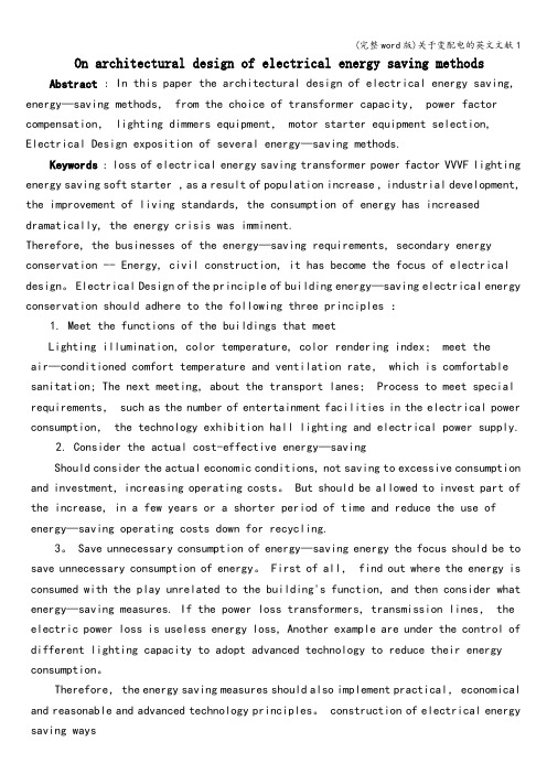
2.2 Software Debugging, h(t)and R (t) At least, there are two ways to improve the software reliability. The first is reducing the errors during programming by using software-engineering principle, and correcting the remaining bugs by debugging and preoperation. The second is error toleration design. Both ways should have the aid of reliability analysis. Compared with the hardware failure, the software failure has the different ,characteristic in a computer system. Generally, the fai1ura:rate. of software system is reduced along the operation time, as Fig.1. Both h(t) and R(t) are descending function in time section (O,+oo). Suppose the initial error number in software is N, thus the h(t) simply increase along the increasing of N, R(t) stmply decrease along the increasing of N.
t
Failure rate
2.1 Hazard Function h(t) and Reliability Degree R(t) Software reliability can be described as reliability degree (the probability of no failure operation): Pt I E } R( E, t ) =Pr { ' where E is the special environment of software system, t is given time, T is the operation time from t = 0 to software failure. R(E,t) has following characteristics: R( E, 0 ) = 1: l h (E, +CO) =O; R(E, t ) decrease simply in the time secllon(0,h). R ( E, t ) simply signed as R ( t ).
R(t) = exp [
Key Words: Software Engineering Computer System Substation Automation
1. Preface
Reliability
Ji (ddx 1
The reliability of computer system, especially industrial computer system, is a key problem. As the quite great progress of hardware manufacture, the reliability of the hardware system is satisfied in areas from normal, commercial applications to industrial and space applications. The software reliability becomes much serious comparatively. For the high requirement of reliability of integrated substation automation computer system (abbreviated as ISACS), that of the hardware system is basically satisfied, and much attention should be put on the software reliability during the research on ISACS and system manufacture. Suitable countermeasure should be discussed and be used.
error number is the function of time, N(t). When following condition is satisfied: 1) {N (t), t3O) has non- interrelated increment, 2) P( N(t + h ) N(t) 3 2 ) = o(h). 3) P ( N( t + h )-N(t)> 1) = h(t) * h + o(h), 4) N(O)=O. N(t) is nonhomogeneous Poisson Process with intensity Mt).
2 . 3 Some Measurements in ISACS Software
The program volume: (necessary bit number): V=N*lnn
0 1998 IEEE
-68-
where N = program length; n = the word nuiiibcr Software complex degree: E=V/L where, L = software abstract level (<1) Software developing time: T=E/S where, S = programmer working speed (efficiency). S is a experience data. Program module complex degree: It contains length, data flow, agglomeration degree, functions and the complex degree of control flow. Connection complex degree between modules: It contains connections, the control flow complex degree, data flow complex degree, probability relation matrix and understandability degree, The measurements of reliability: It contains initial error number N,hazard function X(t), reliability degree R(t) , failure rate Q(t) = 1 - R(t), the mean time between failures MTBF, the mean time to failure M’ITF, etc.
I
Hazard function h(t) is the probability density of failure per unit time at the time t when the system has even been operated normally (no failure) from time 0 to time t. h(t)At = Pr { t CTG t + At I P t } The relation between h(t) and R(E, t ):
Software Reliability in Integrated Substation Automation Computer System
Gao QinXiang
Beijing Electric Power College Beijing 100044,P.R.China
Abstract : The reliability of computer system is a key problem in substation automation. Software reliability of Jntegrated Substation Automation Computer System ([SACS) is described in this paper. By discussing software reliability modeling and analyses, the ideas and technology of @nproving software reliability are given.
Time
Fig.1 Failure Rate of Software and Hardware
The software errors can be divided as serious errors and normal ones by their effects on R(t). Based on above ideas, more attention should be paid on software testing, debugging and correcting errors especially serious errors in programming, testing and preoperation periods. Therefore, the h(t) could keep low. And with some error toleration design, the software reliability would be greatly improved. Another question relative to software reliability is the observability of errors, including predictability. Only the predictable errors can be avoided. And, only observable errors can be checked out and corrected. Many theories and methods are concerned-.with this. Except for normal analysis, it is urgent and necessary to find suitable reliability models for scientific analyses, further more, to resolve software reliability problem.