One-step hydrothermal synthesis of anatase TiO2_reduced graphene
用电池级纳米层状磷酸铁制备磷酸铁锂研究

用电池级纳米层状磷酸铁制备磷酸铁锂研究徐丹; 肖仁贵; 柯翔; 马志鸣【期刊名称】《《电源技术》》【年(卷),期】2019(043)009【总页数】5页(P1415-1418,1426)【关键词】磷酸铁; 磷酸铁锂; 表面活性剂【作者】徐丹; 肖仁贵; 柯翔; 马志鸣【作者单位】贵州大学化学与化工学院贵州贵阳550025【正文语种】中文【中图分类】TM912Goodenough等[1]在1997年发现橄榄石结构的LiFePO4在电势值3.4V(vs.Li+/Li)下能可逆的嵌脱锂离子后,由于其合成成本低、无毒、安全稳定性好等优点,成为了目前锂电池广泛使用的正极材料。
电池级磷酸铁锂常采用高温固相法[2]、水热法[3]、溶胶-凝胶法[4]、共沉淀法[5]等方法来进行制备与研究,磷酸铁锂在充电过程中形成的磷酸铁相,在放电过程中两相重新进行转化。
鉴于磷酸铁及磷酸铁锂在电化学过程中相互转化特性,因此,磷酸铁也成为制备电池级磷酸铁锂的重要前驱体,通过对磷酸铁进行改性成为有电化学活性的材料[6-9],导电层的包覆[10-11],金属离子掺杂[12-13],纳米化和材料形貌的设计[14-17],复合材料[18]等方法成为磷酸铁的重要改性方法。
磷酸铁的形貌特性对制备磷酸铁锂的电化学特性有重要影响[19]。
邵辰[20]通过控制溶液pH值制备纳米球状磷酸铁前驱体,通过高温固相法研制球状磷酸铁锂;吴肇聪[21]等以聚乙二醇为表面活性剂,利用溶胶凝胶法改善磷酸铁锂形貌,提高其电化学性能。
常用高温固相法以磷酸铁为前驱体来制备磷酸铁锂,为了更有效将磷酸铁与锂源进行充分接触,改善高温固相法反应均匀性,提高磷酸铁锂的电化学性能,本文通过表面活性剂,控制磷酸铁形貌结构与颗粒大小,并探讨了磷酸铁形貌对后续制备磷酸铁锂的形貌影响,同时研究磷酸铁锂正极材料的电化学特性。
1 实验材料与方法1.1 材料的制备以三价铁盐、磷酸、硝酸等为原料,在未加其它添加剂或者添加十二烷基硫酸钠(SDS)表面活性剂后,利用DF-101S集热式恒温加热磁力搅拌器进行液相反应结晶,过滤、洗涤、干燥后制备出磷酸铁,未添加SDS制备的前驱体磷酸铁记为FP;添加SDS制备的前驱体磷酸铁记为D-FP。
一步水热法制备手性碳量子点
Material Sciences 材料科学, 2019, 9(6), 549-557Published Online June 2019 in Hans. /journal/mshttps:///10.12677/ms.2019.96070One-Step Hydrothermal Synthesis of ChiralCarbon Quantum DotsYao Wang, Yupeng Lu, Yuanzhe Li, Lumeng Wang, Fan ZhangCollege of Materials Science and Engineering, Taiyuan University of Technology, Taiyuan ShanxiReceived: May 21st, 2019; accepted: Jun. 4th, 2019; published: Jun. 11th, 2019AbstractCarbon Quantum Dots (CQDs) have many excellent properties, such as low toxicity, biocompatibil-ity, photoluminescence, etc., which play an important role in many fields such as photocatalytic electrocatalytic chemical sensing in biological imaging and endowing CQDs with chiral proper-tiesto broaden its applications in chiral recognition and separation and asymmetric catalysis and chiral detection. Chiral carbon quantum dots (L-CQDs and D-CQDs) were synthesized by one-step hydrothermal method using tryptophan (L-Trp and D-Trp) as carbon source and chiral source and sodium hydroxide as reaction regulator. The optical properties and surface structures of L-CQDs and D-CQDs were characterized by high resolution lens electron microscopy, elemental analyzer, ultraviolet-visible absorption spectrometer, steady-state fluorescence spectrometer and circu-lar dichroism (CD). The results show that the prepared L-CQDs and D-CQDs with particle size less than 10 nm presented similar characteristics and optical properties, with strong fluores-cence characteristics and the property of stimulating independence, whose the maximum emis-sion wavelength is 476 nm as well as the optimal excitation wavelength is 360 nm. CD signals taking on mirror symmetry feature near 223 and 290 nm indicate that L-CQDs and D-CQDs are enantiomers.KeywordsHydrothermal Method, Chirality, Carbon Quantum Dots, Circular Dichroism一步水热法制备手性碳量子点王耀,鲁羽鹏,李远哲,王璐梦,张帆太原理工大学材料学院,山西太原收稿日期:2019年5月21日;录用日期:2019年6月4日;发布日期:2019年6月11日王耀 等摘要碳量子点(Carbon Quantum Dots, CQDs)有着很多优良的特性,如:低毒性、生物相容性、光致发光等特性,在生物成像、光催化、电催化、化学传感等许多领域起着重要的作用,赋予CQDs 手性特性。
过渡金属纳米复合材料的制备及其电催化性能研究
摘要目前,人类社会面临严重的化石能源危机和环境污染问题,这些问题已经极大地威胁人类社会的可持续发展。
而减少化石燃料使用依赖于电催化能源转换和电化学储存设备的大规模应用。
目前,这些设备的性能受到了以下几个电化学反应动力学的限制(即氧还原反应、析氢反应和析氧反应)。
一些贵金属如Pt,Ir,Ru被认为是高效电催化剂。
但是它们的稀缺性和价格昂贵阻碍了其规模化应用。
因此,高效的非贵金属电催化剂的设计制备受到了人们极大的关注。
本论文主要设计制备了一系列廉价金属基电催化剂,并通过合理的结构设计提升了材料在不同类型电催化转化反应中的活性。
主要内容如下:(1)卟啉基氧还原催化剂:将带有不同基团的铁卟啉包覆在碳管表面作为前驱体,再经过热解后形成不同结构的Fe-N-C催化剂。
实验证明TPP-CHO中的醛基在热解过程中产生的氧使铁氧化成Fe3O4,阻止了铁元素还原成Fe或Fe3C,Fe3O4@FeNC-700表现出较差的氧还原催化活性。
而TPP-CN中的氰基有助于形成高活性的Fe-N x活性位点,材料热解后形成Fe/Fe3C@C颗粒和Fe-N x活性位点均匀分布在碳管表面,Fe/Fe3C和Fe-N x的协同作用提高了催化剂的催化活性,Fe3C@FeNC-700催化剂表现出比Pt/C更优异的稳定性和抗甲醇性能。
(2)模板导向Co3O4催化剂的合成:首先通过模板PVP和温度调控Co-MOFs的形貌结构,然后将制备的Co-MOFs煅烧,得到一系列具有不同形貌结构的Co3O4纳米复合材料。
其中Co3O4-85中空微米花具有比表面积大、导电性良好等特点,因此在碱性电解液表现出良好的的析氧、析氢性能。
且全解水性能优异,当电解池电流密度达到10 mA cm-2,所需要的电压为1.67 V。
因此,本催化剂的电解水性能优于很多非贵金属催化剂,在电解水应用中有着广阔的前景。
(3)用于全解水的Cu2O@CoV/CF复合物纳米线:本部分通过将Cu(OH)2纳米线与双金属盐一步水热法制备出双金属离子掺杂的中空Cu2O纳米线复合材料。
热解β-环糊精合成发蓝光的石墨烯量子点
热解β-环糊精合成发蓝光的石墨烯量子点佚名【摘要】以β-环糊精为原料,采用一步热解法制备了发蓝光的石墨烯量子点;合成的石墨烯量子点厚度为1-2层的石墨烯,平均大小为27 nm,且发光具有激发波长的依赖性,加之石墨烯量子点发光稳定,无光漂白,低毒,具有良好的生物兼容性,使其在生物成像领域具有重要应用。
%Blue luminescent graphene quantum dots ( GQDs ) were synthesized via a one-step pyrolytic route from beta-cyclodextrin .The obtained GQDs have single-layer and double-layer graphene sheets thick and an average diameter of 27 nm,and exhibit wavelength-dependent luminescence emission .In addition, GQDs have advantages including photoluminescence stability and resistance to photobleaching ,low toxicity and excellent biocompatibility which could facilitate their applications in bioimaging field .【期刊名称】《蚌埠学院学报》【年(卷),期】2015(000)004【总页数】4页(P36-39)【关键词】石墨烯量子点;β-环糊精;热解;蓝光【正文语种】中文【中图分类】O613.71石墨烯因其具有单原子厚的二维结构以及优异的力学、热学、化学及电学性质而受到极大的关注[1]。
然而石墨烯的带隙为零,不能产生荧光。
通过将微米级的石墨烯切割成几个纳米大小的石墨烯量子点,可以形成一定的带隙,并产生发光。
一步水热法合成SiO2纳米棒
Studies in Synthetic Chemistry 合成化学研究, 2018, 6(2), 23-28Published Online June in Hans. /journal/sschttps:///10.12677/ssc.2018.62004Synthesis of SiO2 Nanorodes by One-StepHydrothermal ProcessShuhong Sun, Yin He, Yongmao Hu, Yan Zhu*Kunming University of Science and Technology, Kunming YunnanReceived: Mar. 20th, 2018; accepted: May 2nd, 2018; published: May 10th, 2018AbstractSiO2 nanorodes were successfully synthesized by a simple low-cost one-step alkaline hydrother-mal process using commercial silicate glass at 170˚C. The SEM results show that ammonia concen-tration and holding time play an important role in the formation of SiO2nanorods. XRD results confirmed that the synthesized SiO2nanorods were amorphous. Photoluminescence results showed that the synthesized nanorodes exhibited a strong, sharp photoluminescence emission peak, centered at 410 nm.KeywordsSiO2 Nanorode, Hydrothermal Process, Silicate Glass一步水热法合成SiO2纳米棒孙淑红,贺胤,胡永茂,朱艳*昆明理工大学,云南昆明收稿日期:2018年3月20日;录用日期:2018年5月2日;发布日期:2018年5月10日摘要以商业硅酸盐玻璃为原材料,在170˚C下,通过简单的低成本一步水热法成功制备了SiO2纳米棒。
怎样描述rd图谱
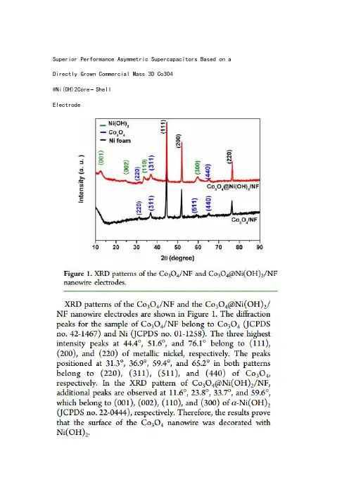
Superior Performance Asymmetric Supercapacitors Based on a Directly Grown Commercial Mass 3D Co3O4@Ni(OH)2Core−ShellElectrodeFacile Synthesis of Hollow MoS2Microspheres/Amorphous Carbon Composites and Their Lithium Storage PropertiesBroad and weak peakIn situ assembly of MnO2nanowires/graphene oxide nanosheets composite with high specific capacitancestrong and clear peakNickelecobalt hydroxide nanosheets arrays on Ni foamfor pseudocapacitor applicationsOne-pot hydrothermal synthesis of reduced graphene oxide/Ni(OH)2 films on nickel foam for high performance supercapacitorsRapid synthesis of graphene/cobalt hydroxide composite with enhanced electrochemical performance for supercapacitorsSynthesis of ultrathin mesoporous NiCo2O4nanosheets on carbon fiber paper as integrated high-performance electrodes for supercapacitorsA sandwich-type three-dimensional layered double hydroxide nanosheet array/graphene composite: fabrication and high supercapacitor performanceUltrathin and highly-ordered CoO nanosheet arrays for lithium-ion batteries with high cycle stability and rate capabilityNi–Co sulfide nanowires on nickel foam withultrahigh capacitance for asymmetricsupercapacitorsOn e-step synthesis of CoNi2S4 nanoparticles for supercapacitor electrodes3D Ni3S2 nanosheet arrays supported on Ni foamfor high-performance supercapacitor and nonenzymatic glucose detectionHigh-performance NiCo2O4@Ni3S2 core/shell mesoporous nanothorn arrays on Ni foam for supercapacitorsNickele Cobalt hydroxide microspheres electrodepositioned on nickelcobaltite nanowires grown on Ni foam for high-performance pseudocapacitorsA novel porous coral-like as an anode material for lithium ion batteries with excellent rate performanceHydrated Cobalt Nickel Molybdate Nanorods as Effectively Supercapacitor Electrode MaterialsMicrowave-assisted synthesis of graphene/CoMoO4 nanocompositeswith enhanced supercapacitor performanceCoMoO4$ nanorods grown on reduced graphene oxide as advanced electrochemical pseudocapacitor materialsFacile fabrication and perfect cycle stability of 3D NiO@CoMoO4 nanocomposite on Ni foam for supercapacitorsFacile hydrothermal synthesis of hierarchical ultrathin mesoporousNiMoO4 nanosheets for high performance supercapacitorsNano a-NiMoO4 as a new electrode for electrochemical supercapacitorsComparison of the Electrochemical Performance of NiMoO4 Nanorods and Hierarchical Nanospheres for Supercapacitor ApplicationsSeaurchin-like hierarchical NiCo2O4@NiMoO4core–shell nanomaterials for high performance supercapacitorsControlled Growth of NiMoO4 Nanosheet andNanorod Arrays on Various Conductive Substrates as Advanced Electrodes for Asymmetric SupercapacitorsDesign and synthesis of 3D Co3O4@MMoO4 (M=Ni, Co) nanocomposites as high-performance supercapacitor electrodesEnhanced performance of supercapacitors with ultrathin mesoporous NiMoO4 nanosheets。
水热合成制备水化硅酸钙-聚氨酯纳米复合材料的结构分析
Key words: calcium silicate hydrate polyurethane nanocomposites; hydrothermal synthesis; calcium silicon ratio; micro
3566
硅 酸 盐 通 报
水泥混凝土
第 40 卷
艺。 相反,Shen 等 [8] 、Kanchanason 等 [9] 和 Plank 等 [10] 研究表明有机聚合物不能嵌入 C-S-H 层间,认为聚合
物被吸附在 C-S-H 的表面或孔隙中,从而影响其结构。 此外,Khoshnazar 等 [11-12] 提出,聚合物可以部分嵌入
C-S-H 夹层中,剩余部分吸附在表面或孔隙中。 聚氨酯( PU) 是一种综合性能优异的高分子材料,它已成功
地用于制备插层黏土基纳米复合材料,并可以改善复合材料的性能 [13-14] 。 至今有关 PU 与 C-S-H 相互作用
的研究很少,为了更加有效地控制纳米复合材料的性能,需要更深入地研究有机和无机复合材料的相互作用
聚合物与 C-S-H 结构的相互作用机理仍然存在争议。 Pelisser 等 [4] 、Wang 等 [5] 和 Zhou 等 [6-7] 认为,聚合物可
以嵌入 C-S-H 层间,且表明插层的成功取决于合适的聚合物类型和浓度、主体 C-S-H 的钙硅比以及合成工
收稿日期:2021-04-28;修订日期:2021-06-15
形貌,这表明水热法可以合成 C-S-H 纳米复合材料。 不同钙硅比 C-S-H 的微观结构有较大的差异:钙硅比为
水热法合成无机半导体纳米材料及其掺杂稀土发光纳米材料
广西师范大学硕士学位论文水热法合成无机半导体纳米材料及其掺杂稀土发光纳米材料姓名:陶萍芳申请学位级别:硕士专业:无机化学指导教师:方岳平20080501陶萍芳广西师范大学硕士学位论文 2008水热法合成无机半导体纳米材料及其稀土发光纳米材料2005级无机化学纳米材料方向研究生:陶萍芳导师:方岳平中文摘要水热溶剂热制备技术是一种设备简单、操作容易的常用制备手段。
该法的主要优势在于多数材料能够在临近临界点的加热加压系统下,在一种适宜的溶剂中溶解。
自Heath及其合作者开拓了利用溶剂热法制备半导体纳米线的新方法之后,这种方法就被广泛的用于一维和空心纳米结构材料的合成与研究工作。
因此,我们选择水热法作为我们的制备手段。
本论文研究的主要目在于通过简单的水热法,探索合成不同的无机半导体纳米材料和稀土发光材料,通过对反应产物的各种测试表征结果进行分析,结合一些常见的生长机制,提出合理的模型来解释合成的纳米材料的生长机制;同时,对合成的纳米材料进行了性能测试,以期待制备的材料具有特别的物理性质。
论文的主要内容介绍如下:第一章简单介绍了纳米材料及其发展过程,叙述了纳米材料的性质、制备方法、表征手段以及稀土发光材料的研究进展。
对纳米材料的合成现状进行了概述,重点介绍了水热法在纳米材料的合成中的应用。
第二章简单介绍了通过无模板和表面活性剂技术,用水热法成功的制备了碲化银纳米管。
制备的样品用X-射线粉末衍射(XRD),场发射扫描电镜(SEM),透射电子显微镜(TEM),X-射线光电子能谱(XPS)和拉曼光谱表征。
探讨了碲化银晶型转变。
并基于低温β-碲化银内在的晶体结构提出了卷曲机理来解释碲化银纳米管的形成过程。
拉曼光谱分析表明,样品显示出有趣的拉曼散射增强现象。
第三章主要是采用简单的溶液-液相-固相(SLS)方法,一步合成了围绕金属Sn核垂直生长出一层In(OH)3纳米棒的蒲公英状核壳微球(Sn@[In(OH)3纳米棒])。
One-pot hydrothermal synthesis of Al-containing SBA-3 mesoporous materials
One-pot hydrothermal synthesis of Al-containing SBA-3mesoporousmaterialsEwa Janiszewska ⇑Adam Mickiewicz University,Faculty of Chemistry,Grunwaldzka 6,60-780Poznan,Polanda r t i c l e i n f o Article history:Received 8December 2012Received in revised form 9February 2014Accepted 10March 2014Available online 18March 2014Keywords:AlSBA-3synthesisAluminium incorporation Acidic properties FTIR +pyridine NH 3-TPDa b s t r a c tAlSBA-3mesostructured materials with different Si/Al ratios were directly synthesized for the first time.The influence of the synthesis medium (different pH of synthesis mixture)and aluminium source on the efficiency of aluminium incorporation was studied.The increase in pH of reacting mixture allows to introduce much higher number of Al atoms,but on the other hand it causes worse ordering of the struc-ture.The aluminium isopropoxide used as Al source leads to relatively high Al content in the final mate-rials.The presence of Al in the framework positions is proved by 27Al MAS NMR.The obtained materials show considerable catalytic activity for the acid-catalyzed reactions (dehydration of 2-propanol,cumene cracking).Ó2014Elsevier Inc.All rights reserved.1.IntroductionZeolites,due to their regular arrays of uniformly sized channels,strong surface acidity and large amount of active sites are exten-sively applied in industry as heterogeneous catalysts and sorbents [1].Processing of large organic molecules in fine chemical produc-tion often requires a molecular sieve with a larger pore size than that of conventional zeolites.The discovery of ordered mesoporous M41S family with controllable pore size from 1.5to 10nm offers an opportunity for processing of bulky molecules [2,3].However,the acidity of alumino-and metalosilicate mesoporous materials is always distinctively lower compared with zeolites [4,5].Limited hydrothermal stability of these materials,either in steam or in hot water [6,7]restricts their broad application.Therefore many efforts have been undertaken to improve their stability [8–11]or to prepare other,more robust and stable,mesoporous materials [9,12,13].SBA-15silica mesoporous materials [13]with more regular structure and thicker walls show much higher stability than MCM-41[14]due to contribution of some micropores connecting mesopores [15].The microporosity of SBA-3is more pronounced than those in SBA-15[16].However,the absence of active sites in the framework of these all siliceous materials limits their applications.Incorporation of aluminium or other metal cations into the amorphous walls of mesoporous silica materials is crucialto generate their catalytic activity [4].Nevertheless,it is very diffi-cult to incorporate metal species into the SBA-n siliceous frame-work by direct synthesis due to the difficulties in the formation of metal–O–Si bonds under required strongly acidic conditions [17].Therefore,most attempts are focused on the post-synthesis incorporation of heteroatoms [18,19].However,there are some disadvantages with these processes,such as complex experimental conditions,non uniform distribution of active sites and contribu-tion of extra-framework species which could block the channels.Therefore,it is challenging to find a simple one-step route to prepare the metalosilicate SBA-n materials with well ordered structure,uniform distribution of the heteroatoms within the framework and efficient catalytic functionality.There are only a few papers reporting a direct synthesis of metal-substituted SBA-n materials including the synthesis under weak acidic condi-tions [20],‘‘pH-adjusting’’[21],semi-crystallizing the framework or using zeolite units to modify the wall of SBA-n [22].For AlSBA-15and AlSBA-1both post-synthesis alumination and direct synthesis have been reported [19],while for AlSBA-3only the post-synthesis methods have been developed [23,24].Although the thermal and hydrothermal resistance of SBA-15and SBA-3are similar,the procedure of SBA-3synthesis is much simpler (lower temperature,one step of heating).It was also reported that the efficiency of niobium incorporation into the skel-eton of SBA-3was the highest amongst other hexagonally ordered mesoporous materials (like MCM-41,SBA-15).The NbSBA-3mate-rials were also more effective catalysts in gas phase oxidative dehydrogenation of propane and liquid phase oxidation of cyclo-hexene than the corresponding NbMCM-41and NbSBA =15[25]./10.1016/j.micromeso.2014.03.0131387-1811/Ó2014Elsevier Inc.All rights reserved.⇑Tel.:+48618291239;fax:+48618291555.E-mail address:eszym@.plThe aim of this study was a direct synthesis of AlSBA-3contain-ing exclusively tetrahedrally coordinated aluminium.The influence of aluminium source as well as the pH of the initial mixture on the textural and surface properties of obtained samples was investi-gated.The resulted materials were characterized by various phys-icochemical methods that prove an incorporation of aluminium into the structure and assess their structural/textural properties. The evaluation of the acidic properties of the materials has been estimated by means of NH3-TPD,FTIR with adsorbed pyridine as probe molecule and by catalytic test of2-propanol dehydration and cumene cracking.2.Experimental2.1.SynthesisAll SBA-3materials were synthesized according to the proce-dure reported by Stucky et al.[26].Cetyltrimethylammonium bro-mide(CTABr,Aldrich)and tetraethylorthosilicate(TEOS,Aldrich) were used as a porogeneous agent and silica source,respectively. Aluminium nitrate(Al(NO3)3Á9H2O,POCh,Poland),aluminium iso-propoxide(Al(isop)3,Aldrich)or aluminium sulphate(Al2(SO4)3-Á16H2O,POCh)were used as aluminium precursors.Concentrated HCl aqueous solution(37%,POCh)was used as the acid source. Aqueous ammonia(25%,POCh)was used to adjust the pH of the initial mixture.The aluminosilicate SBA-3samples were synthe-sized in strongly acidic condition according to following proce-dure:CTABr was dissolved in diluted HCl and then solution of aluminium source was admitted dropwise to the acidic CTABr solution.After stirring for15min,TEOS was added gradually(Si/ Al=50–2)with continuous stirring for next30min.It resulted in formation of white gel.The molar composition of the gel was1 Si:0.02–0.5Al:0.125CTABr:10.9HCl:164H2O.The typical strongly acidic medium was used for preliminary syntheses.In further experiments pH of the suspension was increased up to 2.2or 3.1value,respectively with aqueous ammonia.Stirring was continued for another2h and then the mixture was left at ambient,static condition for22h.The resulting precipitate was filtered,dried and calcined in air at550°C for8h.The same proce-dure was used for Al-free SBA-3for comparison.The samples were labeled as follows:x Al-y(z)where:x stands for Si/Al ratio,y stands for pH of the synthesis:2for synthesis at pH=2.2,3for synthesis at pH=3.1,z defines Al source:(n)–alumin-ium nitrate,(s)–aluminium sulphate,(i)–aluminium isopropoxide.2.2.CharacterizationThe obtained samples were characterized by means of standard methods.X-ray diffraction(XRD)patterns were recorded using a Bruker D8Advance diffractometer with Cu K a radiation (k=1.54056Å).Aluminium content in the calcined samples was determined by ICP–OES on a Varian Vista-MPX spectrometer.The BET surface area and pore parameters of the samples were deter-mined by nitrogen adsorption–desorption isotherm measurements at77K on a Quantachrome Nova1000sorptometer.The samples were outgassed at300°C prior to the measurement.Pore size dis-tribution were calculated from the desorption branch of the isotherm by the Barrett-Joyner-Halenda(BJH)method.The micro-porous surface was estimated using the t-plot method.Solid27Al MAS NMR analysis was performed on a Bruker AMX300WB spec-trometer.Solid29Si MAS NMR analysis was performed on a Varian 400MHz spectrometer.The Fourier transform infrared spectra were recorded with Bruker Tensor27spectrophotometer.Pyridine was used as basic probe agent.The samples were pressed under low pressure into a thin wafers and placed in the vacuum cell.The samples were outgased at400°C for2h and then pyridine was adsorbed at room temperature.The desorption was carried out for30min at each of the following temperatures:100,200, 300and400°C.The spectra were recorded at room temperature. NH3-TPD measurements were performed in aflow reactor.In a typical experiment,about40mg of sample was heated in He stream at the rate of10°/min up to500°C and kept at that temper-ature for0.5h,then cooled down to120°C and afterwards satu-rated with ammonia for0.5h.The physically adsorbed NH3was removed by purging with heliumflow at120°C for1h.The TPD analysis was carried in a range100–600°C with a heating rate 10°C/min.The desorbed NH3was detected and recorded by a TCD analyzer.The catalytic activity of the samples were examined in the 2-propanol(POCh)decomposition and cumene cracking(Aldrich). The catalytic tests were conducted in a pulse microreactor at-tached to the gas chromatograph(Chrom-5)equipped with TCD. The catalyst powder samples(0.015g)were activated in helium stream at350°C(2-propanol)or450°C(cumene)for0.5h prior to the catalytic tests.The decomposition of2-propanol was carried out at230°C and cumene craking at350°C for all samples.The volume of the injected substrate was1l l.3.Results and discussion3.1.X-ray diffractionThe pore ordering of the samples was confirmed by low angle XRD analysis.The presence of aluminium in the reacting mixture did not disturb the formation of SBA-3structure.As displayed in Fig.1,the samples showed typical patterns of the hexagonal phase of SBA-3,matching well those reported in the literature[23].The XRD patterns of AlSBA-3samples showed three well-resolved sharp peaks of higher intensity in comparison to intensity of peaks of all silica SBA-3samples.It indicated better ordering of AlSBA-3 samples than that of pure silica SBA-3(Fig.1A).Probably it can be caused by promoting role of anion accompanying the Al atoms which could affect the interaction of the surfactant with the silicate species.Similar effect was observed in synthesis of MCM-41mate-rials[27]or zeolites[28].The addition of some amount of certain anions to the synthesis mixture of MCM-41materials or zeolites reduced the synthesis time.The increase in pH of initial mixture resulted in a little lower intensity of XRD reflections which can re-sult from lower ordering of the products(Fig.1B).The source of aluminium does not influence the ordering markedly(Fig.1C).XRD patterns in the wide angle range were recorded in order to check the presence of any crystalline phase in resulted samples. We did not notice any distinct diffraction reflections corresponding to any crystalline phase(Fig.2),although some sensitivity limits of XRD in case of low content,small particles(below3nm)or very high dispersion of potential admixture should be taken into an ac-count.Only very broad band in the2h range15–30°is noticeable, which is always attributed to amorphous silica.3.2.Low-temperature nitrogen adsorption and ICP resultsThe composition and textural properties of resulting mesopor-ous materials are shown in Table1.The elemental analyses of all samples indicate much lower Al content in the products than in starting gels.It indicates that only a small fraction of aluminium is included into the walls.The same observations were reported for Al-bearing SBA-15or SBA-1[17,19,29].The low content of Al introduced into the products results from the fact,that applied acidic medium is much below isoelectric point of Al3+cations and subsequently difficult formation of Si–O–Al bands.The78 E.Janiszewska/Microporous and Mesoporous Materials193(2014)77–84isomorphous substitution of silicon in SBA-3for aluminium strongly depends on the Al source and pH of the synthesis mixture,as evidenced by the data in Table parison of the aluminium content in samples synthesized with the same source of alumin-ium (i.e.nitrate)at different pH in range 2–3indicates that in-crease in pH of the reacting mixture results in negligible augmentation of Al number.The Al 3+cations and positive charge of silica species existing in the synthesis mixture at low pH (<1)do not interact with each other because of the same charge.There-fore aluminium atoms are not introduced to the structure.If the pH of the synthesis mixture rises above the zero net charge of silica (pH >2),the Si species become negatively charged which enhances the interaction with the Al 3+species.The use of Al(NO 3)3or Al 2(SO 4)3causes the introduction of the lowest amount of alumin-ium,whereas the use of Al(isop)3allows to introduce the highest amount of aluminium under the same condition of syntheses.As the condition of synthesis are similar (pH,time of synthesis)the differences in the amount of introduced Al atoms can be caused by different reactivity of the Al species in the gel formed of the three aluminium sources towards bonding with Si species during the gelation process.The samples obtained with using inorganic source of aluminium (nitrate or sulphate)indicate similar AlTable 1Structural properties of samples.SampleSynthetic conditions Si/Al (ICP)S BET (m 2g À1)S mic /S macV pore (cm 3g À1)Aver.pore diam.(nm)Source of AlpH Si/Al (gel)Si-0–<11–107111.80.49 2.4550Al-0(n)Nitrate <1501126912.60.66 2.37Si-2–2.21–9537.30.46 2.6650Al-2(n)Nitrate 2.2503031081 6.30.76 2.8320Al-2(n)Nitrate 2.220314133111.00.76 2.3010Al-2(n)Nitrate 2.210135155715.70.78 2.002Al-2(n)Nitrate 2.2249.5163815.20.73 2.19Si-3–3.11–74811.70.45 2.4250Al-3(n)Nitrate 3.150********.40.81 2.8520Al-3(n)Nitrate 3.120178132712.40.71 2.1310Al-3(n)Nitrate 3.110103149815.70.70 1.882Al-3(n)Nitrate 3.1235.6151720.70.64 1.7050Al-2(s)Sulphate 2.25067786910.70.56 2.5720Al-2(s)Sulphate 2.220357126112.80.69 2.1910Al-2(s)Sulphate 2.210169135413.90.73 2.162Al-2(s)Sulphate 2.2236149217.00.64 1.7150Al-2(i)Isopropox 2.2501431056 6.90.73 2.7520Al-2(i)Isopropox 2.22060123310.50.64 2.0810Al-2(i)Isopropox 2.21026.7136014.20.65 1.912Al-2(i)Isopropox2.224.4107815.30.511.86‘‘–‘‘–Not measured.E.Janiszewska /Microporous and Mesoporous Materials 193(2014)77–8479content.Substantially higher Al loading in samples prepared with Al(isop)3can result from the presence of isopropanol generated upon hydrolysis which affects somewhat polarity of the system and does not generate additional anions(NO3Àor SO42À)potentially competing with silicate,therefore it facilitates bonding the liber-ated Al3+cations with just formed silicic acid.The recorded nitrogen adsorption/desorption isotherms are of type IV characteristic for mesoporous materials.The pure silica and aluminosilicate materials synthesized at higher pH show sim-ilar isotherms.Only samples,prepared at pH=2.2and3.1with Si/ Al molar ratio of50,show an isotherms with a steep rise in adsorbed volume at relative pressure p/p0>0.8,corresponding to relatively larger pore size(Table1).As the relative pressure increases to ca.p/p0$0.2isotherms of all samples containing alu-minium show a sharp step characteristic of capillary condensation of nitrogen within uniform mesopores(Fig.3A and C).Uniformity of mesopores of aluminosilicate samples is well visible in pore size distribution curves(Fig.3B).The other textural parameters vary more or less depending on the pH,source of aluminium or Al con-tent.The surface area and pore volume slightly decreases with growing pH of the synthesis mixture(regardless of the aluminium presence).This effect can be explained regarding the rate of silica condensation.At an elevated pH value a higher degree of silicate condensation is attained.The more rapid condensation should not impair the micelles markedly and subsequently less pro-nounced interaction lead to a lower surface area and pore volume. The presence of Al in the initial mixture results in some increase in surface area and pore volume in comparison to all silica SBA-3even if aluminium atoms are not incorporated into the resulted struc-ture(sample Si-0and50Al-0(n)).As the synthesis of SBA-3mate-rials is performed in a relatively short time(22h)it can be the effect of promoting action of anions accompanying aluminium that allow to obtain better ordering of the structure.These observation was also confirmed by XRD analysis.The synthesis in the presence of NO3Àanions allows to obtain higher BET value in comparison to the series obtained in the presence of SO42À.The same effect was observed by Laha et al.in the synthesis of MCM-41[27].The authors showed,that at the same promoter concentration,the time required for obtaining a well-ordered MCM-41decreased with increasing charge/radius(Z/r)ratio of the central atom of the pro-moter anion.It explain better promoting role of nitrate in compar-ison to sulphate anion.The pH does not affect the pore diameter and volume for all silica samples,whereas introduction of Al results in their increase.Pore volume for the series of samples synthesized in the presence of nitrate and sulphate at pH=2.2 increases up to Si/Al ratio of10and then decreases.In series pre-pared with Al isopropoxide at pH=2.2and nitrate at pH=3.1the pore volume decreases with aluminium content.The average pore diameter also decreases with the growing Al content in the mate-rials for all the studied series.The decreasing pore volume and average pore size can be explained by increasing contribution of micropores with increasing Al loading calculated by t-plot method (Table1).The second possible explanation of lower pore volume for the samples with the highest amount of Al is a blocking the pores by extra-framework aluminium species(observed in27Al MAS NMR spectra).All textural parameters are slightly higher for samples synthesized in the presence of aluminium nitrate (amongst all series synthesized at the same pH with different Al source).It is a result of mentioned before the best promoting role of nitrate groups.3.3.Promoting role of oxyanions on SBA-3structure formationThe hydrothermal syntheses of all silica SBA-3at pH=2.2were carried out in the presence or absence of sodium salts of nitrate or sulphate to check the promotion role of these oxyanions on the course of syntheses of SBA-3structure.Different SiSBA-3series were preparing by varying the synthesis time(0–22h).The con-centration of promoter was the same(oxyanion/Si molar ratio was0.05).The XRD patterns of samples obtained at different time show that the synthesis of ordered SiSBA-3materials in the pres-ence of nitrate or sulphate anions is faster than in their absence (Fig.4).It proves the promoting role of these anions in the synthe-sis of SBA-3materials.Similarly as in the synthesis of MCM-41[27] the promoting role of nitrate is slightly better than sulphate anion. Similar conclusion provide29Si MAS NMR analysis of samples ob-tained at different times in the presence or absence of these oxya-nions.It is seen,that the ratio of Q4peak(more condensed(SiO)4Si species)to Q3peak(less condensed(SiO)3SiOH species)is higher for samples obtained in the presence of nitrate or sulphate than in that prepared without any promoter,regardless of time of synthesis(Fig.5).It clearly indicates a faster formation of ordered SBA-3structure in the presence of promotors.80 E.Janiszewska/Microporous and Mesoporous Materials193(2014)77–843.4.Metal locationSolid state27Al MAS NMR spectra provide the information on the aluminium species in the samples and confirm an introduction of aluminium atoms into the framework for samples synthesized at higher pH(Fig.6).The signal at46ppm is assigned to tetrahedrally coordinated aluminium species[18,30].The absence of signal around0ppm,corresponding to the octahedrally coordinated alu-minium,indicates that no extra-framework alumina species were formed even upon calcination.Only spectra of calcined samples with the highest Al content indicates some amount of extra-frame-work alumina(À5.5ppm).Lack of any signal in the spectra of sam-ples synthesized at pH<1indicates the absence of any Al in this sample.The all silica composition of the latest sample is also con-firmed by the ICP-OES analysis.3.5.Acidity measurementsThe IR spectra of adsorbed pyridine were measured in order to estimate the strength and nature of acid sites in AlSBA-3materials. All the samples indicate the FTIR bands due to pyridine adsorbed on Lewis acid sites(1455cmÀ1),pyridine adsorbed on Brönsted acid sites(1544cmÀ1)and a band at1490cmÀ1attributed to pyr-idine associated with both Lewis and Brönsted acid sites[31,32].Only the series of samples obtained with aluminium sulphate do not show any band attributed to strong(Brönsted)acid sites even for sample with highest amount of aluminium(Fig.7B).The spec-tra show the bands at1446and1596cmÀ1at lower pyridine desorption temperature due to pyridine hydrogen bonds with sila-nols group and band at1575cmÀ1assigned to weak Lewis-bound pyridine(Fig.8B).Bands attributed to hydrogen-bonded pyridine decay after evacuation at300°C.The band originated from weak Lewis-bound pyridine decays after desorption of pyridine at 300°C only for samples with low aluminium content,whereas it maintains even after evacuation at400°C for samples with high Al loading.Fig.8A compares of chemisorption of pyridine on sam-ples at300°C for samples with different Si/Al ratios synthesized with Al(isop)3.The intensity of band at1455cmÀ1due to Lewis acid sites is much higher in comparison to the intensity of band as-signed to Brönsted acid sites for all series indicating higher amount of Lewis acid sites in samples.The intensity of bands attributed to both,Lewis and Brönsted acid sites,increase with increasing amount of aluminium in the samples.This indicate that the acidity increases with increasing aluminium content.The FTIR spectra of pyridine adsorption on pure silicas SBA-3(sample Si-0or 50Al-0(n),not shown)show no peaks at1455or1544cmÀ1attributed to Lewis and Brönsted acid sites,respectively.The strength of acid sites was evaluated by NH3-TPD analysis. The TPD profiles of all samples show one broad peak in the temper-ature range of200–550°C with maximum at300°C(Fig.9).It cor-responds to the desorption of NH3from the weak,medium and strong acid sites of the materials with great majority of medium acid sites[31].The number of acid sites,calculated(Table2)as well reflected by the amount of chemisorbed ammonia is highest for samples synthesized with isopropoxide and in series increases with Al/Si ratio in starting gel(Fig.9B).These results are in good agreement with activity in reactions requiring acid sites.The aluminosilicate SBA-3materials under study show a remarkable activity in2-propanol decomposition which is in con-trast to all silica samples(Fig.10A).The dehydration reaction to propene results from action of the acid sites on the surface of cat-alysts due to the presence of Al atoms in the structure.The pres-ence of such centres was indicated in the NH3-TPD and FTIR with pyridine as a sonde measurements.The activity increases with the Al content in initial gels for all series and it is consistent with the number of introduced aluminium atoms.The samples obtained by using aluminium sulphate show the lowest activity,whereas the samples synthesized in the presence of aluminium isopropox-ide show the highest activity amongst series synthesized at theE.Janiszewska/Microporous and Mesoporous Materials193(2014)77–848182 E.Janiszewska/Microporous and Mesoporous Materials193(2014)77–84same pH.The series of samples obtained at higher pH show insig-nificant higher activity than the series obtained at lower pH(with the same source of aluminium)due to much higher aluminium content.The samples with the highest aluminium loading show some activity(11–13%)in cumene cracking(Fig.10B).Only the samples synthesized with aluminium sulphate show negligible activity in this reaction similarly as samples of all series with lower aluminium loading suggesting a weak acid strength of their active centres.These results are in good agreement with FTIR with pyri-dine as a sond results.4.ConclusionsThe results reveal for thefirst time that Al can be successfully incorporated into SBA-3by direct synthesis.The presence of Al atoms in tetrahedral framework positions of SBA-3structure has been confirmed by27Al MAS-NMR measurement.The number of Al incorporated in SBA-3structure depends on used source of alu-minium and on pH of synthesis mixture.Some increase in pH of initial mixture is necessary to introduce Al to the structure. Aluminium isopropoxide used as aluminium source allows to introduce the highest amount of aluminium without altering the structural ordering and the textural features.The IR spectra of ad-sorbed pyridine indicate the presence of both Lewis and Broensted acid sites in the samples with introduced Al and the above results are consistent with these of NH3-TPD data exhibiting the prevailing contribution of medium acidic sites.The catalytic activity of theTable2Total number of acid sites evaluated by NH3-TPD(l mol/g).Al/Si pH=2.2pH=3.1 Nitrate Sulphate Isopropoxide Nitrate0.02––––0.0526–39290.125886370.518741320177‘‘–‘‘–Not measured.5020102Si/Al 5020102 isopropox.nitrate, pH=3.1Si/AlFig.10.Conversion(%)2-propanol over samples.E.Janiszewska/Microporous and Mesoporous Materials193(2014)77–8483samples in reaction requiring acidic active sites(2-propanol dehy-dration,cumene cracking)depends on the number of aluminium incorporated into the siliceous framework.AcknowledgmentThe author appreciate National Science Centre forfinancial support from Grant No.N204119238.References[1]G.Bellussi,M.S.Rigutto,in:J.C.Jansen,M.Stöcker,H.G.Karge,J.Weitkamp(Eds.),Advanced Zeolite Science and Applications,Stud.Surf.Sci.Catal.,vol.85, Elsevier,Amsterdam,1994,pp.177–213.[2]J.S.Beck,J.C.Vartuli,W.J.Roth,M.E.Leonowicz,C.T.Kresge,K.D.Schmitt,C.T.-W.Chu,D.H.Olson,E.W.Sheppard,S.B.McCullen,J.B.Higgins,J.L.Schlenker,J.Am.Chem.Soc.114(1992)10834–10843.[3]C.T.Kresge,M.E.Leonowicz,W.J.Roth,J.C.Vartuli,J.S.Beck,Nature359(1992)710–712.[4]A.Corma,Chem.Rev.97(1997)2373–2420.[5]A.Corma,V.Fornés,M.T.Navarro,J.J.Pérez-Pariente,J.Catal.148(1994)569–574.[6]J.M.Kim,J.H.Kwak,S.Jun,R.Ryoo,J.Phys.Chem.99(1995)16742–16747.[7]D.Trong On,S.M.J.Zaidi,S.Kaliaguine,Micropor.Mesopor.Mater.22(1998)211–224.[8]J.M.Kim,S.Jun,R.Ryoo,J.Phys.Chem.B103(1999)6200–6205;R.Ryoo,S.Jun,J.M.Kin,M.J.Jim,mun.(1997)2225–2226.[9]K.R.Kloetstra,H.Van Bekkum,J.C.Jansen,mun.(1997)2281–2282.[10]R.Mokaya,W.Jones,mun.1997(2185–2186)(1998)1839–1840.[11]R.Mokaya,Angew.Chem.111(1999)3079;R.Mokaya,Angew.Chem.Int.Ed.Engl.38(1999)2930–2934.[12]S.S.Kim,W.Zhang,T.J.Pinnavaia,Science282(1998)1302–1305.[13]D.Y.Zhao,J.Feng,Q.Huo,N.Melosh,G.H.Fredickson,B.F.Chmelka,G.D.Stucky,Science279(1998)548–552.[14]F.Kleitz,W.Schmidt,F.Schüth,Micropor.Mesopor.Mater.65(2003)1–29.[15]R.Xu,W.Pang,J.Yu,Q.Huo,J.Chen,Chemistry of Zeolites and Related PorousMaterials:Synthesis and Structure,J.Wiley&Sons(Asia)P LTD,Singapore, 2007.pp.467–601.[16]R.Ryoo,C.H.Ko,M.Kruk,V.Antochshuk,M.Jaroniec,J.Phys.Chem.B104(2000)11465–11471.[17]A.Vinu,V.Murugesan,W.Böhlmann,M.Hartmann,J.Phys.Chem.B108(2004)11496–11505.[18]N.Lin,Y.Yang,Z.Y.Wu,H.J.Wang,J.H.Zhu,Micropor.Mesopor.Mater.139(2011)130–137.and references therein.[19]M.Hartmann,A.Vinu,S.P.Elangovan,V.Murugesan,W.Böhlmann,Chem.Commun.11(2002)1238–1239.and references therein.[20]Y.Yue,A.Gédéon,J.-L.Bonardet,N.Melosh,J.-B.D’Espinose,J.Fraissard,Chem.Commun.(1999)1967–1968.[21]S.Wu,Y.Han,Y.-C.Zou,J.-W.Song,L.Zhao,Y.Di,S.-Z.Liu,F.-S.Xiao,Chem.Mater.16(2004)486–492.[22]D.T.On,S.Kaliaguine,Angew.Chem.Int.Edit.40(2001)3248–3251.[23]O.A.Anunziata,M.L.Martínez,M.G.Costa,Mater.Lett.64(2010)545–548.[24]M.L.Martínez,M.B.Gómez Costa,G.A.Monti,O.A.Anunziata,Micropor.Mesopor.Mater.144(2011)183–190.[25]B.Kilos,A.Tuel,M.Ziolek,J.C.Volta,Catal.Today118(2006)416–424.[26]Q.Huo,D.I.Margolese,U.Ciesla,D.G.Demuth,P.Feng,T.E.Gier,P.Sieger,A.Firouzi,B.F.Chmelka,F.Schüth,G.D.Stucky,Chem.Mater.6(1994)1176–1191.[27]ha,R.Kumar,Micropor.Mesopor.Mater.53(2002)163–177.[28]R.Kumar,P.Mukherjee,R.K.Pandey,P.Rajmohanan,A.Bhaumik,Micropor.Mesopor.Mater.22(1998)23–31.[29]V.V.Balasubramanian,C.Anand,R.R.Pal,T.Mori,W.Böhlmann,K.Ariga,A.K.Tyagi,A.Vinu,Micropor.Mesopor.Mater.121(2009)18–25.[30]G.Engelhardt,in:H.van Bekkum,E.M.Flanigen,P.A.Jacobs,J.C.Jansen(Eds.),Introduction to Zeolite Science and Practice,2nd Revised and Expanded Edition,Stud.Surf.Sci.Catal.,vol.137,Elsevier,Amsterdam,2001,pp.387–418.[31]Y.Li,W.Zhang,L.Zhang,Q.Yang,Z.Wei,Z.Feng,C.Li,J.Phys.Chem.B108(2004)9739–9744.[32]T.Klimova,J.Reyes,O.Gutiérrez,L.Lizama,Appl.Catal.A335(2008)159–171.84 E.Janiszewska/Microporous and Mesoporous Materials193(2014)77–84。
水热因子定义
水热因子定义1. 引言水热因子是指在水热条件下影响化学反应速率和平衡的因素。
水热条件是指在高温和高压的环境下,在液相水存在的情况下进行实验。
在水热条件下,水的物理和化学性质将发生显著改变,从而对化学反应的进行产生重要影响。
因此,了解和控制水热因子对于实现特定化学反应的目标是至关重要的。
2. 水的性质与水热因子2.1 水的物理性质水是一种普遍存在于地球上的物质,其特殊的性质是由其分子结构和氢键网络所决定的。
在常规条件下,水是液态,具有相对较高的沸点和蒸发热。
然而,在高温和高压的水热条件下,水的物理性质将发生重大变化。
2.2 水的溶解性水是一种广泛应用于溶剂的物质,在化学反应中起着重要的作用。
水的溶解性取决于溶质与溶剂之间的相互作用。
在水热条件下,溶解性可能会发生显著改变,因为随着温度和压力的升高,溶剂的性质发生变化,从而影响了溶质的溶解性。
2.3 水的酸碱性水可以发生自离解平衡反应,生成氢离子(H+)和氢氧根离子(OH-)。
水的酸碱性常常用pH来表示,pH值越低表示酸性越强,pH值越高表示碱性越强。
在水热条件下,水的酸碱性也会发生变化,从而影响溶解度和化学反应的进行。
3. 水热因子的影响3.1 温度水热条件下,温度是一个极其重要的因素。
随着温度的升高,溶液中溶质分子的运动速度增加,反应速率也随之增加。
此外,高温还可以破坏某些化学键,从而改变反应的产物分布和化学平衡。
3.2 压力水热条件下,压力也是一个关键因素。
增加压力可以压缩水的体积,从而增加水分子之间的相互作用力,提高溶剂的密度。
这种改变可以影响溶解度和反应速率。
此外,高压还可以改变化学反应的平衡常数。
3.3 水的溶解性水热条件下,溶解性是一个重要的因素。
随着温度的升高,溶液中溶质的溶解度可能会发生变化。
在一些情况下,随着温度的升高,溶液中的溶质溶解度也会增加。
这种变化可能是由于水分子的结构和相互作用力的改变所致。
3.4 水的酸碱性水热条件下,水的酸碱性可能会发生显著改变。
- 1、下载文档前请自行甄别文档内容的完整性,平台不提供额外的编辑、内容补充、找答案等附加服务。
- 2、"仅部分预览"的文档,不可在线预览部分如存在完整性等问题,可反馈申请退款(可完整预览的文档不适用该条件!)。
- 3、如文档侵犯您的权益,请联系客服反馈,我们会尽快为您处理(人工客服工作时间:9:00-18:30)。
One-step hydrothermal synthesis of anatase TiO 2/reduced graphene oxide nanocomposites with enhanced photocatalyticactivityDayu Liang a ,Can Cui a ,⇑,Haihua Hu b ,Yaping Wang a ,Sheng Xu a ,Beili Ying a ,Peigang Li a ,Bingqing Lu a ,Honglei Shen aa Center for Optoelectronics Materials and Devices,Department of Physics,Zhejiang Sci-Tech University,Hangzhou 310018,China bZhejiang University City College,Hangzhou 310015,Chinaa r t i c l e i n f o Article history:Received 10April 2013Received in revised form 29July 2013Accepted 9August 2013Available online 20August 2013Keywords:TiO 2Reduced graphene oxide Hydrothermal Photocatalysisa b s t r a c tA facile and efficient one-step hydrothermal approach has been developed to synthesize chemically bonded TiO 2/reduced graphene oxide (RGO)nanocomposites with Ti(SO 4)2and graphene oxide (GO)as precursors and ethanol/water solvent as a reducing agent.This approach aims to realize a partial reduc-tion of GO and a growth of anatase TiO 2nanoparticles on RGO sheets simultaneously.The morphology and microstructure characterizations of TiO 2/RGO nanocomposites reveal that this method leads to close interfacial contact of TiO 2/RGO and efficient dispersion of TiO 2nanocrystals on the surface of RGO sheets.The TiO 2/RGO nanocomposites exhibit superior photocatalytic activity compared to bare TiO 2nanoparti-cles and a mechanical mixing TiO 2+RGO sample in the degradation of Rhodamine B.Based on the pho-toluminescence spectrum and photocurrent response measurements,the enhanced photocatalytic activity of TiO 2/RGO is mainly attributed to the excellent electron trapping and transportation properties of RGO.Ó2013Elsevier B.V.All rights reserved.1.IntroductionTiO 2has received much attention as a promising semiconductor photocatalytic material for uses in solar energy conversion and pollutant treatment,owning to its high redox potential,cheapness,nontoxicity and chemical stability [1,2].However,the rapid recom-bination of photogenerated electron–hole pairs in TiO 2nanoparti-cles results in a low quantum efficiency and poor photocatalytic activity [3].In the last decade,various strategies have been devel-oped to suppress the recombination of photogenerated electron–hole pairs in TiO 2.Coupling TiO 2with other semiconductor (ZnO,CdS,WO 3,and Bi 2WO 6)[4–7]or carbonaceous substance [8,9]to form heterojunction nanostructure is an efficient method to reduce the electron–hole pairs recombination rate of TiO 2.Graphene,a single layer of sp 2-bonded carbon atoms,is suitable for using as a photocatalyst support material due to its unique properties,such as excellent electrical conductivity,high theoreti-cal specific surface area,flexible structure,exceptional transpar-ency and adsorption activity [10,11].Recent reports indicate that hybridizing TiO 2nanoparticles with graphene can lead to efficient electron–hole separation and enhance the electronic and photocat-alytic properties of TiO 2in a large degree [12,13].However,it is dif-ficult to realize high yields of single-layer graphene sheets since many synthesis routes like mechanical exfoliation,epitaxial growth or chemical vapor deposition are limited by the high cost and particularly complex process [14,15].Therefore,RGO obtained from partial reduction of GO in solution has been widely used as an inexpensive substitute for graphene [16].Because of the residual oxygen-containing functional groups on the sheet surface,the hydrophilic RGO can form close interfacial contact with nanoparti-cles by chemical bonds and be able to suspend in both polar and non-polar solvents [17].In the past years,several methods,such as sol–gel method,hydrothermal treatment and UV or micro-wave-assisted reduction method,have been used to synthesize TiO 2/RGO nanocomposites with improved electronic or photocata-lytic performance [18–20].However,it is almost inevitable that these synthesis processes are realized by mechanically mixing TiO 2nanoparticles with the suspension of GO and then reducing GO into RGO in an additional step.These two-step synthesis strat-egies always lead to a weak interfacial contact and poor dispersion of nanoparticles on RGO sheets.What is more,strong reducing agents such as hydrazine are involved in the reduction process of a conventional synthesis,which may destroy the 2-dimentional structure and reduce the electron properties of RGO seriously [21].Therefore,it is still urgent to develop facile,green and effi-cient ways to prepare high quality TiO 2/RGO nanocomposites in large scale.Herein,we report a facile one-step hydrothermal method to synthesize TiO 2/RGO nanocomposites with Ti(SO 4)2and GO0925-8388/$-see front matter Ó2013Elsevier B.V.All rights reserved./10.1016/j.jallcom.2013.08.062Corresponding author.Tel.:+86057186843832.E-mail address:cancui@ (C.Cui).solutions as starting materials in an ethanol/water solvent. Well-crystalline anatase TiO2nanoparticles and large RGO sheets were synthesized simultaneously during the hydrothermal pro-cess.TiO2nanoparticles were well dispersed on RGO sheets and tight interfacial contact was achieved by chemical bonds between TiO2and the residual oxygen-contained functional groups on the surface of RGO sheets.As a result,the TiO2/RGO nanocomposites exhibited superior photocatalytic activity compared to bare TiO2nanoparticles and the mechanical mixing TiO2+RGO.2.Experimental2.1.MaterialsPristine graphite and Rhodamie B(RhB)were purchased from Fisher Scientific (Hong Kong)Co.,Ltd.Ti(SO4)2was supplied by Shanghai Chemical Reagent Com-pany.All the reagents were at analytical grade and used without further purifica-tion.The deionized water was produced from a Millipore Milli-Q water purification system and used throughout the whole experiment.2.2.Synthesis of TiO2/RGO nanocompositesFig.1shows the schematic illustration of the synthesis process.The GO suspen-sion was obtained by the modified Hummers method as described elsewhere [22,23].TiO2/RGO nanocomposites were prepared using Ti(SO4)2and0.5mg/ml GO aqueous suspension as the starting materials.In a typical preparation process, 0.48g Ti(SO4)2was added into20ml of ethanol and then a certain amount of GO suspension was gradually dropped into the solution.Subsequently,deionized water was added to get a total volume of40ml.After stirring for1h,the obtained solution was transferred into a50ml Teflon-sealed autoclave and maintained at180°C for 9h in a furnace.Finally,the resulting products were isolated by centrifugation at 6000rpm for10min,washed with deionized water and ethanol several times and then dried in an oven at70°C for12h.We refer to the as-prepared TiO2/RGO nanocomposites with5ml,10ml,15ml,and20ml GO suspension in the starting solution as TiO2/RGO-1,TiO2/RGO-2,TiO2/RGO-3,TiO2/RGO-4,respectively.For comparison,pure TiO2nanoparticles and RGO were also synthesized under the same conditions in the absence of GO and Ti(SO4)2,respectively.A sample denoted as TiO2+RGO was prepared by mechanical mixing TiO2and RGO with RGO mass ratio similar to TiO2/RGO-4.2.3.CharacterizationsThe phase structure of the samples was characterized by X-ray diffraction (XRD)on a Bruker D8diffractometer using Cu K a(k=1.5406Å)radiation at 2.4.Photocatalytic activity measurementThe photocatalytic tests were carried out at room temperature under atmo-spheric pressure in a quartz reactor system.In a typical process,25mg of the pho-tocatalyst was added to50ml aqueous solution containing 4.17Â10À5M Rhodamine B(RhB)in a150ml quartz beaker.The suspension was stirred in the dark for30min to get an adsorption–desorption equilibrium.Then the suspension was exposed to a250W high pressure hydrargyric lamp under magnetic stirring. During illumination,a circulation of water through an external cooling coil was conducted to maintain the temperature of suspension at about25°C.Then samples of the suspension were obtained at5min intervals.The concentration of RhB in all the samples was estimated by measuring the absorbance at the maximum peak (554nm)with a UNICO UV-4802H spectrophotometer.2.5.Photocurrent response measurementThe TiO2,TiO2+RGO and TiO2/RGO-4electrodes for use in the photocurrent measurement were prepared by the doctor-blade method onfluorine-doped SnO2 (FTO)conductive glass.Briefly,0.1g of photocatalyst was dissolved in about1ml ethanol to form slurry.The slurry was coated onto FTO glass to form a uniformfilm, and then thefilm was heated in vacuum at400°C for2h.The transient photocur-rent characterization was carried out using a standard three-compartment cell,con-sisting of a working electrode,a platinum counter electrode,and an Ag/AgCl reference electrode.The electrolyte was0.5M Na2SO4aqueous solution degassed with N2and the illumination source was a150W halogen tungsten lamp.3.Results and discussionFig.2shows the XRD patterns of the samples.The XRD pattern of GO reveals a reflection peak at2h=10.7°,which corresponds to interlayer spacing of0.83nm.The XRD patterns of TiO2and TiO2/ RGO can be indexed to anatase TiO2(JCPDS21-1272).In contrast to other titanium precursors,Ti(SO4)2is more inclined to form well-crystalline TiO2nanoparticles during the low-temperature hydrothermal process and the conventional calcination treatment for TiO2crystallization is not mandatory in our method.In our experiment,the(002)peak of RGO at26.5°is not shown in the TiO2/RGO samples[24],which may be due to the disappearance of the layer-stacking regularity of RGO after intercalation by TiO2 nanoparticles[25].The average crystallite sizes of TiO2nanoparti-cles in all the samples were calculated to be around10nm with the Scherrer equation based on the full width at half maximum (FWHM)of(101)peak[26].The similar crystallite size of anatase TiO2nanoparticles in different samples indicates that the incorpo-Fig.1.The schematic illustration of the reduction of GO and in situ growth of TiOnanoparticles on RGO sheets via hydrothermal process.Fig.2.XRD patterns of GO,TiO2,and TiO2/RGO.D.Liang et al./Journal of Alloys and Compounds582(2014)236–240237the skeletal vibration of C@C.The other peaks at1730,1380,1220 and1058cmÀ1are assigned to stretching vibrations of oxygen-containing groups carboxyl C@O,carboxyl C A O,epoxy C A O and alkoxy C A O[28],respectively.The FTIR spectrum of TiO2/RGO-4 demonstrates that most of the oxygen-containing functional groups have been removed as the peaks associated with the oxy-gen-containing groups decrease dramatically,implying that GO was significantly reduced in the hydrothermal process.However, it is notable that a small fraction of oxygen-containing functional groups still exist and facilitate the hybridizing of TiO2nanoparti-cles on the RGO sheets.Fig.4shows the Raman spectra of the TiO2,GO and TiO2/RGO-4 samples.For the TiO2,four Raman peaks at around153cmÀ1, 400cmÀ1,528cmÀ1and636cmÀ1are associated with the E g,B1g, B1g+A1g and E g modes of anatase TiO2[29],respectively.The Ra-man spectrum of GO shows two characteristic peaks,namely,the D band at1355cmÀ1and the G band at1600cmÀ1.The D band is assigned to edge or in-plane sp3defects and disordered carbon, whereas the G band arises from the in-plane vibration of ordered sp2-bonded carbon atoms[30].All the above mentioned Raman peaks are observed in the spectrum of TiO2/RGO-4,whereas theintensity ratio of D bands and G bands(I D/I G)decrease for GO to1.004for TiO2/RGO-4.The decreased I D/I Gspectrum of TiO2/RGO-4also confirms the partial reduction It is easy tofind platelets of RGO sheets among the TiO2nanopar-ticles.Figs.5(c)and(d)are the TEM images of TiO2/RGO-4in low and high magnification.Fig.5(c)shows that the crumpled RGO sheets are uniformly covered by TiO2nanocrystals.The crystallo-graphic spacing of0.352nm in Fig.5(d)matches well with the (101)crystallographic plane of anatase TiO2.The RGO sheets can be identified from the edges of TiO2nanoparticles in Fig.5(d). The SEM and TEM images coupled with the FTIR and Raman spec-tra offer sufficient evidence for the tight coupling of RGO sheets with anatase TiO2nanoparticles.The UVDRS spectra have been measured to investigate the opti-cal absorption property of TiO2/RGO nanocomposites(Fig.6).The bare TiO2exhibits the fundamental absorption at around390nm corresponding to the bandgap energy of3.2eV in the ultraviolet re-gion[31,32].Compared with that of the bare TiO2,a gradual red-shift to longer wavelengths is observed for the TiO2/RGO with increasing RGO mass ratio in the nanocomposites.The red-shift of the absorption onsets is ascribed to the formation of Ti A O A C bond[33],which causes the bandgap of the nanocomposites to be-come narrower.Accordingly,as shown in the inset of Fig.6,the col-or of the TiO2/RGO suspensions in ethanol changed from white to grey and then dark with increasing RGO mass ratio.The photocatalytic performance of TiO2/RGO nanocomposites was evaluated by degradation of RhB.The bare TiO2nanoparticles and mechanical mixing TiO2+RGO were used as reference sam-ples.Fig.7shows the photocatalytic degradation curves of RhB as a function of time.The photocatalytic performance of different photocatalysts follows the order of TiO2<TiO2/RGO-1<TiO2/ RGO-2<TiO2+RGO<TiO2/RGO-3<TiO2/RGO-4,indicating that the successful incorporation of RGO in the nanocomposites can en-hance the photocatalytic performance of TiO2efficiently.The pho-tocatalytic activity of TiO2+RGO is lower than that of TiO2/RGO-4 even though the two photocatalysts have similar RGO content.The photocatalytic degradation of RhB solution is a pseudo-first-order reaction and its kinetics can be expressed as:-ln(C/C0)=k appÂt, where k app is the apparent photocatalytic reaction rate constant, C0is the initial concentration of RhB before light irradiation and C is the concentration at irradiation time t[34].The k app can be cal-culated from the slope of-ln(C/C0)vs t plots and the values are listed in Fig.8.With the incremental RGO mass ratio,the k app of TiO2/RGO nanocomposites increase from0.0398minÀ1to 0.1472minÀ1.The highest degradation rate observed for TiO2/ RGO-4is about4.6times that of0.0264minÀ1for bare TiO2nano-particles.The mechanical mixing TiO2+RGO sample has a moder-ate k app of0.0973minÀ1.According to other reports of RGO modified TiO2photocatalysts[35],an optimal content of RGO in the nanocomposites was about5%and excess RGO would reduce the photocatalytic performance.PL spectra and photocurrent response measurements have been carried out to evaluate the photogenerated charges recombination and transportation in TiO2/RGO photocatalyst.Fig.9shows the PL spectra of TiO2/RGO nanocomposites with different RGO content. The PL peak at around390nm is ascribed to the bandgap recombi-nation of TiO2,while other luminescence peaks in the range from 425nm to500nm are related to transition from localized surface states to the valence band of TiO2[36].The gradual decrease in PL intensity at around390nm with increasing RGO mass ratio in TiO2/RGO implies the suppression of photogenerated electron recombination from conduction band to valence band in TiO2. The PL spectrum of TiO2+RGO was also measured,and its PL intensity at around390nm is also very weak and is similar to that of TiO2/RGO-2.The photocurrent responses of the TiO2,TiO2+RGO and TiO2/RGO-4electrodes under intermittent illumination(0V vs Ag/AgCl)are shown in Fig.10.The photocurrent response was reversible as the illumination was turned on and off.The photocur-rent density of TiO2/RGO-4electrode is6.97l A cmÀ2,which isFig.3.FTIR spectra of TiO2,GO,and TiO2/RGO-4samples.Fig.4.Raman spectra of TiO2,GO,and TiO2/RGO-4samples.Compounds582(2014)236–240Fig.5.SEM images of(a)TiO2,(b)TiO2/RGO-4,(c)TEM and(d)HRTEM images of TiO2/RGO-4.UV–vis diffuse reflectance spectra(UVDRS)of TiO2and TiO2/RGO,the inset the photos of the suspensions of TiO2and TiO2/RGO in ethanol.RhB photodegradation as a function of illumination time for TiO2,TiO2TiO2/RGO nanocomposites.Fig.8.The plots of-ln(C/C0)vs t of TiO2,TiO2+RGO and TiO2/RGO nanocomposites.Fig.9.PL spectra of TiO2,TiO2+RGO and TiO2/RGO nanocomposites.larger than that of the bare TiO 2and TiO 2+RGO electrodes.The weakened PL intensity and enhanced photocurrent in TiO 2/RGO nanocomposites confirmed the high efficiency of RGO on suppres-sion of photogenerated electron–hole recombination in TiO 2.Be-cause the Fermi level of RGO is more positive than the conduction band of TiO 2[37],the photogenerated electrons in TiO 2conduction band tend to inject into RGO,which act as accep-tors of photogenerated electrons.On the other hand,the high elec-trical conductivity of RGO enables these electrons to transport in the two dimensional p -conjugation structures of RGO sheets rather than recombination with holes that remain in the valence band of TiO 2[38].The relatively poor performance of mechanical mixing TiO 2+RGO compared to TiO 2/RGO-4is ascribed to the weak inter-facial contact and poor dispersion of nanoparticles on RGO sheets.So far,we have confirmed that the RGO sheets with excellent elec-tron trapping and transportation properties can suppress the recombination of photogenerated electron–hole pairs in TiO 2.Moreover,the well-crystalline anatase TiO 2with small crystallite size,the close interfacial contact,and the narrow bandgap in the composite structure are also beneficial to light absorption and electron transport,which ultimately contribute to the enhanced photocatalytic performance of TiO 2/RGO nanocomposites.4.ConclusionsWe have developed a facile and efficient one-step hydrothermal synthesis route to realize a partial reduction of GO and a growth of well-crystalline anatase TiO 2nanoparticles on RGO sheets simulta-neously.The microstructure characterizations indicate that the anatase TiO 2nanocrystals are well dispersed on RGO sheets with chemical bonds in the resulting TiO 2/RGO nanocomposites.The PL and photocurrent response measurements reveal that the TiO 2/RGO can efficiently restrain charges recombination due to the excellent electron trapping and transportation properties of RGO.As a result,the TiO 2/RGO nanocomposites exhibit superior photocatalytic activity compared to bare TiO 2nanoparticles and mechanical mixing TiO 2+RGO in degradation of RhB.The highest apparent photocatalytic reaction rate constant of TiO 2/RGO nano-composites is about 4.6times that of bare TiO 2nanoparticles.AcknowledgmentsThe authors are grateful to Dr.H.R.Sharma in the University of Liverpool for reading the manuscript.This work was supported by the National Natural Science Foundation of China (Nos.60806045and 11074220),Natural Science Foundation of Zhejiang Province (No.Y4100310),Qianjiang Talent Program of Zhejiang Province (2013R10060),Open Foundation of Zhejiang Provincial Top Key Academic Discipline of Applied Chemistry and Eco-Dyeing &Fin-ishing Engineering (No.YR2012008),Scientific Research Fund of Zhejiang Provincial Education Department (No.Y201223380),and 521Talents Project in Zhejiang Sci-Tech University.References[1]A.Fujishima,X.Zhang,D.A.Tryk,Surf.Sci.Rep.63(2008)515–582.[2]J.G.Yu,Q.L.Li,Z.Shu,Electrochim.Acta 56(2011)6293–6298.[3]I.Bannat,K.Wessels,T.Oekermann,J.Rathousky,D.Bahnemann,M.Wark,Chem.Mater.21(2009)1645–1653.[4]R.Murugan,V.J.Babu,M.M.Khin,A.S.Nair,S.Ramakrishna,Mater.Lett.97(2013)47–51.[5]Y.B.Chen,L.Z.Wang,G.Q.Lu,X.D.Yao,L.J.Guo,J.Mater.Chem.21(2011)5134–5141.[6]J.K.Yang,X.T.Zhang,H.Liu,C.H.Wang,S.P.Liu,P.P.Sun,L.L.Wang,Y.C.Liu,Catal.Today 201(2013)195–202.[7]Q.C.Xu,D.V.Wellia,Y.H.Ng,R.Amal,T.T.Y.Tan,J.Phys.Chem.C 115(2011)7419–7428.[8]Y.J.Xu,Y.B.Zhuang,X.Z.Fu,J.Phys.Chem.C 114(2010)2669–2676.[9]L.W.Zhang,H.B.Fu,Y.F.Zhu,Adv.Funct.Mater.18(2008)2180–2189.[10]P.V.Kamat,J.Phys.Chem.Lett.2(2011)242–251.[11]A.K.Geim,Science 324(2009)1530–1534.[12]S.Sun,L.Gao,Y.Liu,Appl.Phys.Lett.96(2010)083113.[13]P.Zabek,J.Eberl,H.Kisch,Photochem.Photobiol.Sci.8(2009)264–269.[14]K.S.Novoselov,A.K.Geim,S.V.Morozov,D.Jiang,Y.Zhang,S.V.Dubonos,I.V.Grigorieva,A.A.Firsov,Science 306(2004)666–669.[15]K.S.Kim,Y.Zhao,H.Jang,S.Y.Lee,J.M.Kim,J.H.Ahn,P.Kim,J.Y.Choi,B.H.Hong,Nature 457(2009)706–710.[16]K.Zhang,K.C.Kemp,V.Chandra,Mater.Lett.81(2012)127–130.[17]D.R.Dreyer,S.Park,C.W.Bielawski,R.S.Ruoff,Chem.Soc.Rev.39(2010)228–240.[18]O.Akhavan,E.Ghaderi,J.Phys.Chem.C 113(2009)20214–20220.[19]G.Williams,B.Seger,P.V.Kamat,ACS Nano.2(2008)1487–1491.[20]W.Chen,L.Yan,P.R.Bangal,Carbon 48(2010)1146–1152.[21]A.O.Khavan,M.Abdolahad,A.Esfandiar,M.Mohatashamifar,J.Phys.Chem.C114(2010)12955–12959.[22]W.S.Hummer,R.E.Offeman,J.Am.Chem.Soc.80(1958)1339.[23]J.F.Shen,Y.Z.Hu,C.Li,C.Qin,M.X.Ye,Small 5(2009)82–85.[24]S.X.Min,G.X.Lu,J.Phys.Chem.C 115(2011)13938–13945.[25]J.Liu,H.Bai,Y.Wang,Z.Liu,X.Zhang,D.D.Sun,Adv.Funct.Mater.20(2010)4175–4181.[26]X.Y.Zhang,H.P.Li,X.L.Cui,Y.H.Lin,J.Mater.Chem.20(2010)2801–2806.[27]Y.Y.Gao,X.P.Pu,D.F.Zhang,G.Q.Ding,X.Shao,M.Jing,Carbon 50(2012)4093–4101.[28]Y.H.Ding,P.Zhang,Q.Zhuo,H.M.Ren,Z.M.Yang,Y.Jiang,Nanotechnology 22(2011)215601.[29]S.Peng,X.Y.Zhang,M.X.Sun,X.L.Cui,Y.H.Lin,Nanoscale 4(2012)1800–1804.[30]Y.H.Zhang,N.Zhang,Z.R.Tang,Y.J.Xu,Phys.Chem.Chem.Phys.14(2012)9167–9175.[31]H.L.Meng,C.Cui,H.L.Shen,D.Y.Liang,Y.Z.Xue,P.G.Li,W.H.Tang,J.AlloysComp.527(2012)30–35.[32]S.W.Liu,C.Liu,W.G.Wang,B.Cheng,J.G.Yu,Nanoscale 4(2012)3193.[33]G.D.Jiang,Z.F.Lin,C.Chen,L.H.Zhu,Q.Chang,N.Wang,W.Wei,H.Q.Tang,Carbon 49(2011)2693–2701.[34]X.H.Wang,J.G.Li,H.Kamiyama,Y.Moriyoshi,T.Ishigaki,J.Phys.Chem.B 110(2006)6804–6809.[35]Y.H.Zhang,Z.R.Tang,X.Z.Fu,Y.J.Xu,ACS Nano 4(2010)7303–7314.[36]Y.T.Liang,B.K.Vijayan,K.A.Gray,M.C.Hersam,Nano Lett.11(2011)2865–2870.[37]Y.Yu,Y.Zhao,S.Ryu,L.E.Brus,K.S.Kim,P.Kim,Nano Lett.9(2009)3430–3434.[38]N.J.Bell,Y.H.Ng,A.Du,H.Coster,S.C.Smith,R.Amal,J.Phys.Chem.C 115(2011)6004–6009.10.The photocurrent response of TiO 2,TiO 2+RGO and TiO 2/RGO-4electrodes.Compounds 582(2014)236–240。