0809-602-2303 MOX Gateway Field Controller User Guide v1.00.01
欧诺克 直流无刷驱动器 产品说明书

深圳市欧诺克科技有限公司Shenzhen ONKE Technology Co., Ltd.座机:*************27381841电话:邓先生135****7106陈先生139****0920邮箱:***************网 址 : 地址:广东省深圳市宝安区福海街道怀德翠湖工业园13栋稳定的质量是我们赖以生存的根本优质的服务是我们继续发展的前提客户的满意是我们唯一追求的目标产品画册Product gallery专业生产直流无刷驱动器、无刷电机及自动化控制系统深圳市欧诺克科技有限公司直流无刷驱动器目录匠心制造精益求精“一、公司介绍03二、直流无刷驱动器091. 驱动器介绍与型号说明092. BC、BC2无刷系列技术指标113. 驱动器应用领域194. 驱动器外设配件21 0102C O M P A N Y PROFILE以精密制造引领未来Leading the future with precision manufacturing公司简介Company Profile深圳市欧诺克科技有限公司成立于2010年,是一家专业研发生产伺服电机和驱动器的高新技术企业,公司技术力量雄厚,检测手段先进,欧诺克人本着不求最全,只求最精的信念,为生产出各类伺服电机、各类驱动器而不懈奋斗。
欧诺克人以鹰的精神,挑战尖端,生产出性价比的各类伺服电机和驱动器,以鹰的敏锐洞察力洞察市场,随时改进、创新来满足市场的需求。
深圳市欧诺克科技有限公司产品主要有:伺服驱动器、伺服电机、直流伺服驱动器,直流伺服电机,交流伺服驱动器,交流伺服电机,低压伺服驱动器,低压伺服电机,直线电机驱动器,DDR马达驱动器,音圈电机驱动器,直流无刷驱动器,直流无刷电机,Rs485,CANopen总线,EtherCAT总线,电子凸轮伺服系统,大功率伺服驱动器、大电流伺服驱动器,专用伺服驱动器和自动化控制系统,十年来凭借精湛的技术与国内国外众多知名企业公司建立了互利共赢的合作。
FUJI贴片机_错误代码表
导向器中将发生的各种错误的内容和其对策。
错误信息的主题与在错误对话框中显示的错误编号相对应。
请选择与错误编号相对应的错误信息的主题。
索引:6101-0010、0011、0012、0013、0014、0015、0016、0017、0018、0019、-0020、0023、0024、0025、0026、0027、0028、0029、-0040、0041、0042、0043、0044、0045、0046、0047、-0080、0081、0082、0083、0084、0085、0086、0087、0088、0089、-0090、0091、0092、0093、0094、0095、0096、0097、-0100、0101、0102、0104、0108、0112、0118、0140、0143、0144、-0201、0210、0211、0220、0221、0222、0223、0224、0225、0226、0227、-0228-0229、-0301、0302、0303、0304、0305、0306、0307、0308、0309、-0400、0401、0402、0403、0404、-0501、0502、0503、-1001、1002、1003、1004、1005、1007、1009、-8010、8011、8012、8013、8020、8021、8022、-001A、001B、001C、001D、001E、001F-002A、002B、002C、002D、002E、-008A、008C、008D、008E、008F、-009C、009D、-02FF、-030A、030B、030C、030D、030E、030F、-7FFF、-8A01、8F01、8F02、8F03、8F04、8F05、8F06、8F07、8F08、8F09、8F10、-8F11、8F12、-8F0A、8F0B、8F0C、8F0D、8F0E、8F0F、611D-0001、0021、0022、0023、0024、0030、0031、0040、-0100、0101、0200、0201、0202、-8000、8001、8002、8003、8004、8005、8006、-8050、8051、-8101、8102、8103、8104、8105、8106、8107、8108、-8200、8201、8202、8203、8204、-8301、8302、-611E-810A、810B、611E-0001、0022、0040、-0101、0102、0103、0104、0105、0106、-0200、0201、0202、-8000、8001、8002、8003、8004、8005、8006、-8050、8060、8070、-8071、-8100、8109、8200、8201、8202、8203、8204、6170-1041、1042、-3001、3002、3003、3004、3005、3006、-6010、6011、6012、6174-6001、6002、6003、6004、6005、6006、6007、-6065、6069、-6101、6102、6103、6104、-8101、内容1、61010010执行错误内容执行所必需的DLL(INIREP.DLL)读入失败。
I-CON工业产品介绍-Gateway

可用作存储离线历史数据文件;
RSLogix5000 Configuration ICG-EIP2MB – RSLogix5000配置举例
Configuration File and RSLinx Browsing ICG-EIP2MB – 配置文件及RSLinx浏览
英孚康工业通讯 产品介绍
XXX 产品经理 frdu@
Industrial Automation& Information Convergence
Agenda
1. 工业2.4G无线网桥 2. 工业总线协议网关 3. 广域GPRS通讯方案 — DF1 over GPRS
Fieldbus Gateway 总线协议网关 — 典型应用
High Availability Serial Gateway – ICG-EIP2MB-R 高可用性网关
EtherNet/IP to Modbus RTU 主站协议转换
双串口在线备用,提供总线高可用性, 有效降低系统停机风险
主串口发生故障时,备用串口自动上线 适于各种高可靠性要求关键场合
管线监控
罐区监控
地铁BAS
High Availability Serial Gateway - Ethernet Redundancy 以太网接口冗余方案
Configuration and Maintenance U 盘配置,方便维护
U盘加载配置文件,最方便、易用 的配置方式;
维护方便:原U盘插入新的模块即 可完成更ห้องสมุดไป่ตู้模块、恢复系统运行。
企业能源管理系统(PEMS) 与不同PLC 子系统、仪表之间的数据通讯 油气罐区监控系统与总线阀门、罐体报警装置、以及现场总线变送器的数据通讯 轨道交通环控系统(BAS) 与冷水机组、电梯、FAS、EPS 及UPS 等设备之间的通讯 矿井、码头等自动化监控系统与皮带保护控制器、电子秤及外围设备PLC 间的通讯
OKI5300印表机的错误代码

如果错误代码您要找的是不是在下面的表格,然后发送电子邮件至support@,我们会找出它的意思。
错误代码描述复苏001机器检查例外一个严重的问题,已发现的铜委员会寻求注意服务的人如果重新启动打印机不正确的问题002DSI公司例外当程式,企图寻找了一个无效的地址注意:24位数字的地址(通常是3 ),然后重新启动打印机。
检查重复性如果可能的。
重复同样的行动,重新启动后打印机和检查,如果同样的服务呼叫讯息出现003ISI的例外当程式,企图寻找了一个无效的地址注意:24位数字的地址(通常是3 ),然后重新启动打印机。
检查重复性如果可能的。
重复同样的行动,重新启动后打印机和检查,如果同样的服务呼叫讯息出现004对齐例外当程式,企图寻找了一个无效的地址注意:24位数字的地址(通常是3 ),然后重新启动打印机。
检查重复性如果可能的。
重复同样的行动,重新启动后打印机和检查,如果同样的服务呼叫讯息出现005程序例外该程序已尝试探讨了一个无效的地址注意:24位数字的地址(通常是3 ),然后重新启动打印机。
检查重复性如果可能的。
重复同样的行动,重新启动后打印机和检查,如果同样的服务呼叫讯息出现006浮动点无法例外该程序已尝试探讨了一个无效的地址注意:24位数字的地址(通常是3 )款中,然后重新启动打印机。
检查重复性如果可能的。
重复同样的行动,重新启动后打印机和检查,如果同样的服务呼叫讯息出现007 教学地址断点例外注意:24位数字的地址(通常是3 ),该程序已尝试探讨了一个无效的地址然后重新启动打印机。
检查重复性如果可能的。
重复同样的行动,重新启动后打印机和检查,如果同样的服务呼叫讯息出现030铜slot1的DIMM内存检查错误一个错误侦测到已在运作的检查,羊年在插槽1 (或驻地RAM的模式,有一个居民的RAM )。
注意:24位数字的地址(通常是3 ),然后重新启动打印机。
检查重复性如果可能的。
重复同样的行动,重新启动后打印机和检查,如果同样的服务呼叫讯息出现030铜slot1的DIMM内存检查错误一个错误侦测到已在运作的检查,羊年在插槽1 (或驻地RAM的模式,有一个居民的RAM )。
OKI新错误代码查询
OKI CONFIDENTIAL
1/39
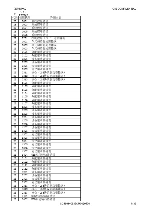
(8)PINPAD 0 (8)PINPAD Service Provider(密码键盘) 代表 错误代码 详细内容 28 2410 USB启动驱动器错误 28 2411 USB启动驱动器错误 28 2412 USB启动驱动器错误 28 3101 分配驱动器错误 28 3102 分配驱动器错误 28 3111 分配驱动器错误 28 3112 分配驱动器错误 28 3201 设备驱动器错误 28 3202 设备驱动器错误 28 3301 协议驱动器错误 28 3302 协议驱动器错误 28 3311 USB协议驱动器错误 28 3312 USB协议驱动器错误 28 3313 USB协议驱动器错误 28 3314 USB协议驱动器错误 28 3401 USB启动驱动器错误 28 3410 USB启动驱动器错误 28 3411 USB启动驱动器错误 28 4101 分配驱动器错误 28 4102 分配驱动器错误 28 4103 分配驱动器错误 28 4104 分配驱动器错误 28 4105 分配驱动器错误 28 4106 分配驱动器错误 28 4107 分配驱动器错误 28 4108 分配驱动器错误 28 4109 分配驱动器错误 28 4111 分配驱动器错误 28 4112 分配驱动器错误 28 4113 分配驱动器错误 28 4114 分配驱动器错误 28 4115 分配驱动器错误 28 4201 设备驱动器错误 28 4202 设备驱动器错误 28 4203 设备驱动器错误 28 4204 设备驱动器错误 28 4205 设备驱动器错误 28 4206 设备驱动器错误 28 4207 设备驱动器错误 28 4208 设备驱动器错误 28 4209 设备驱动器错误 28 4211 设备驱动器错误 28 4212 设备驱动器错误 28 4213 设备驱动器错误 28 4214 设备驱动器错误 28 4215 设备驱动器错误 28 4301 协议驱动器错误 28 4302 协议驱动器错误 28 4303 协议驱动器错误 28 4304 协议驱动器错误 28 4305 协议驱动器错误 28 4306 协议驱动器错误 28 4307 协议驱动器错误 CC4901-0935CM0020500
施乐生产型设备(8000)简易代码表

9-331
MAGE TONER EM
9-332
CYAN TONER EM
9-333
BLACK TOMER EM
9-335 9-336 9-343-344 9-354
AUGER #1 AUGER #2
BELT HOME TOO LONG 转印带自检错误 Y DISPEN BROKEN 黄色显影仓错误
9-355
一般代码为001开头的是机器开关类,比如主门开关、侧门开关;002为操作面板问题;003为数据板问题 显影仓、转印带、2转问题;010为定影器问题;016为服务器通讯问题。 机型 代码(数字) 代码含义(英) 代码含义(中) 测试代码 8000 4-311 4-320-327 FIU TO IO FAIL DRUM DRIV MOTO 接纸器组件不通讯 鼓驱动马达 * 004-004-007
M DISPEN BROKEN
红色显影仓错误
9-356
C DISPEN BROKEN
青色显影仓错误
9-357 9-402-408 9-410-413 9-415-416 10-355 10-359
K DISPEN BROKEN 同9-330-333 同9-354-357 同9-335-336 FUSER OVERHEAT 同10-355
TO
TO
TO
TO TO
744-013
TO
0
744-008 744-009 744-010 744-011 744-012
004为各驱动马达问题;006为激光器及成像问题;007为纸盒问题;008为纸路问题;009为粉仓、 个人经验 此代码是提示主机与接纸器通讯不好,可能是代码未开启,可能是硬件 故障。根据实际情况判断排查,确认。 此代码是提示四个鼓组件驱动马达转动不好,可通过测试代码测试是否 正常。 此代码与331-332-333为同组代码,代码含义为粉仓含量检测有错误,可 能为传感器问题,可能为下粉问题,所以要测试下粉马达,搅粉马达, 以及粉仓传感器马达。 此代码与330-332-333为同组代码,代码含义为粉仓含量检测有错误,可 能为传感器问题,可能为下粉问题,所以要测试下粉马达,搅粉马达, 以及粉仓传感器马达。 此代码与330-331-333为同组代码,代码含义为粉仓含量检测有错误,可 能为传感器问题,可能为下粉问题,所以要测试下粉马达,搅粉马达, 以及粉仓传感器马达。 此代码与330-331-332为同组代码,代码含义为粉仓含量检测有错误,可 能为传感器问题,可能为下粉问题,所以要测试下粉马达,搅粉马达, 以及粉仓传感器马达。 此代码提示为废粉杆驱动马达或者传感器有问题,可通过检查和用代码 测试来排查。 此代码提示为废粉杆驱动马达或者传感器有问题,可通过检查和用代码 测试来排查。 此代码为转印带自检错误,确定转印带本身、转印带架子、转印带边位 传感器无问题后,修改代码可解决。否则,根据实际情况判断解决。 此代码提示为黄色显影仓状态,0为正常,1、2、3均为有问题。确认显 影仓本身,粉仓下粉正常后,修改代码解决。 此代码提示为红色显影仓状态,0为正常,1、2、3均为有问题。确认显 影仓本身,粉仓下粉正常后,修改代码解决。 此代码提示为青色显影仓状态,0为正常,1、2、3均为有问题。确认显 影仓本身,粉仓下粉正常后,修改代码解决。 此代码提示为黑色显影仓状态,0为正常,1、2、3均为有问题。确认显 影仓本身,粉仓下粉正常后,修改代码解决。 备用代码
OKUMA报警号2049

2230 不能使用 左侧指令
2231 下标指令
2232 系统变量设定值有错
2233 局部变量使用数溢出
2234 程序非法指令 单位指定
2235 未选择程序名
2236 无程序结束代码
2237 不能使用 任选程序段跳步
2238 不能使用 RSTRT
2261 数据字 G22 指令不妥
2262 数据字 规格代码
2263 数据字 G 代码
2264 数据字 M 代码
2265 MD 特殊G 代码
2266 主顺序
2267 复位检索
2268 正向超程
2269 负向超程
2270 无运算功能
2271 无系统变量规格
2272 无子程序规格
2165 MCS 编码器初始化异常
2166 MCS 别置型编码器异常
2167 MCS 别置型编码器初始化异常
2168 MCS 光栅尺异常
2169 MCS 光栅尺初始化异常
2170 MCS 磁编码器异常
2171 MCS 旋转变压器异常
2172 MCS 脉冲发生器计数溢出
2209 表达式 局部变量
2210 程序非法指令 G 代码
2211 程序非法指令 M 代码
2212 程序非法指令 公共变量
2213 程序非法指令 系统变量
2214 程序非法指令 顺序名
2215 程序非法指令 数字数据
2217 程序非法指令 字符的使用
2218 程序非法指令 程序名
2049 PLC 轴行程极限超程
2050 PLC 轴指令
2051 PLC 轴连续定位溢出
MOX EtherNet_IP网关应用手册-v1.0

EtherNet/IP网关应用手册MOX中国自动化有限公司2011年7月目录1.所适用的MOX网关 (4)2.所需环境 (4)3.AB PLC侧配置 (4)3.1PLC配置 (4)3.2EtherNet/IP网络配置 (6)3.3下载配置到PLC (11)4.MOX 网关侧配置 (11)4.1MOXIDE配置 (11)4.2MOXGRAF配置 (15)本文主要参考以下文档:1. 所适用的MOX网关本文档所描述的内容适用如下的MOX网关:2. 所需环境本应用需要如下软硬件环境:3. AB PLC侧配置配置PLC和EtherNet/IP网络使用RSLogix5000 编程软件。
首先配置PLC,其次配置EtherNet/IP网络。
打开RSLogix5000程序,遵循以下步骤。
3.1 PLC配置建立一个新项目文件或打开现有项目。
建立一个新配置,打开File并选择NEW。
在出现的对话框中选择所需要的PLC类型,在本示例中使用的PLC类型为1756-L61。
同时输入控制器名字并选择背板类型,控制器槽号以及项目保存路径。
点击OK接受设置。
添加PLC然后添加EtherNet/IO模块。
右键点击窗口左侧导航目录中的I/O configuration目录,如下图所示。
添加新模块(Ethernet模块)点击new module并选择所需要的Ethernet模块,在本示例中选择1756-ENBT/A (Ethernet Bridge)。
这个模块是PLC中的扫描器模块,如下图所示。
选择模块类型输入所需的配置,下图红色方框中的内容需要根据实际情况进行填写。
填写完成后点击OK按钮完成配置。
配置Ethernet模块3.2 EtherNet/IP网络配置第二步配置EtherNet/IP网络并在PLC配置中添加MOX EtherNet/IP从站模块。
设置程序为“Offline”模式,然后右键点击在I/O configuration中的EtherNet/IP bridge模块,并选择“New Module”。
- 1、下载文档前请自行甄别文档内容的完整性,平台不提供额外的编辑、内容补充、找答案等附加服务。
- 2、"仅部分预览"的文档,不可在线预览部分如存在完整性等问题,可反馈申请退款(可完整预览的文档不适用该条件!)。
- 3、如文档侵犯您的权益,请联系客服反馈,我们会尽快为您处理(人工客服工作时间:9:00-18:30)。
MOX Gateway Field ControllerUser Guide0809-602-2303PrefaceScope of the User GuideThis MOX Gateway Controller User Guide contains information for MOX Gateways with the following part numbers:Part Number DescriptionsDPMX602-30-05-08-00 PROFIBUSMX602-30-05-08-02 PROFIBUS DP (GSM/GPRS)MX602-30-05-10-00 ControlNETMX602-30-05-15-00 SerialThis guide has been organized for the operator, and it is expected that the user is an engineer, technician, electrician or similar with an understanding of the operating and programming requirements of related MOX products.Related DocumentsTypical application of the gateway module contains a collection of MOX equipment and several software packages. For this reason, a number of related documents should be read in conjunction with this user guide.The related documents are noted below:•MOX Unity Field Controller User Guide•MoxIDE User Guide•MoxGRAF User GuideConventions UsedWhen you see the “exclamation mark” icon in the left-hand margin, the text to its immediate right will be a special note. Please ensure that you read this information to increase your understanding of the systems operation.When you see the “stop sign” icon in the left-hand margin, the text to its immediate right will be a warning. This information could prevent injury loss of property or even death (in extreme cases). It is very important that you stop and read this information and ensure that you have complete understanding before continuing with the procedures.Contents1OVERVIEW (1)2SPECIFICATIONS (2)2.1K EY F EATURES (2)2.2O PTIONS (2)2.3PROFIBUS DP(MX602-30-05-08-00/MX602-30-05-08-02) (3)2.3.1Familiarization (3)2.3.2Datasheet (4)2.3.3Key Features (5)2.3.4LED Indication (5)2.3.5Configuration (7)2.4C ONTROL NET(MX602-30-05-10-00) (16)2.4.1Familiarization (16)2.4.2Datasheet (17)2.4.3Key Features (17)2.4.4LED Indication (18)2.4.5Configuration (20)2.4.6Redundancy (20)2.5S ERIAL (MX602-30-05-15-00) (21)2.5.1Familiarization (21)2.5.2Datasheet (22)2.5.3Key Features (22)2.5.4LED Indication (22)2.5.5Configuration (24)3INSTALLATION (25)3.1H ANDLING C ONSIDERATIONS (25)3.1.1Electrostatic Discharge (25)3.1.2Environmental Precautions (25)3.2M OUNTING THE MOX G ATEWAY AND A SSOCIATED C OMPONENTS (26)3.2.1Installation Considerations (26)3.2.2Preventing Excessive Heat (26)3.2.3Installation Cleanliness (27)3.2.4Mounting the Controller (27)3.2.5Typical MOX Gateway Dimensions (27)3.2.6Terminal Connector (28)3.2.7Grounding Considerations (28)3.3C ABLE P ATH C ONSIDERATIONS (29)3.3.1Minimizing Electrical Noise on Analog Signal Lines (29)3.3.2Analog Signal Cable Grounding (30)3.4P OWER (31)3.4.1Power Requirement (31)3.4.2Power Isolation (31)3.4.3Power Consumption Calculations (31)3.4.4DC Power Wiring (User DC Source) (33)3.5I NSTALLING C OMMUNICATION C ABLES (34)3.5.1Serial Ports (34)3.5.2Ethernet Ports (36)3.5.3GSM/GPRS (37)3.6A PPLYING P OWER (39)4CONFIGURATION WITH MOXGRAF (40)4.1C REATE N EW P ROJECT (40)4.2D EFINE V ARIABLES (41)4.3V ARIABLES A DDRESSING (41)4.4I/O W IRING (43)5TYPICAL SYSTEM (45)APPENDIX A PRODUCT SUPPORT (46)FiguresF IGURE 1MX602-30-05-08-00MOX PROFIBUS DP G ATEWAY F AMILIARIZATION (3)F IGURE 2MX602-30-05-08-02MOX PROFIBUS DP(GSM/GPRS)G ATEWAY F AMILIARIZATION (4)F IGURE 3S ET UP A N EW P ROJECT (8)F IGURE 4A DD PROFIBUS M ASTER (8)F IGURE 5S ET PROFIBUS DP G ATEWAY C ONNECTION D RIVER (9)F IGURE 6S ET IP A DDRESS AND C ONNECT TO S ERVER (9)F IGURE 7A CTUAL N ETWORK C ONFIGURATION (10)F IGURE 8B UILD A N EW P ROJECT IN M OX IDE (10)F IGURE 9S ERIAL P ORT C ONFIGURATION P AGE (11)F IGURE 10A LTERING COM1S ETTINGS (12)F IGURE 11IP C ONFIGURATION A PPLICATION (14)F IGURE 12MX602-30-05-10-00MOX C ONTROL NET G ATEWAY F AMILIARIZATION (16)F IGURE 13MX602-30-05-15-00MOX S ERIAL G ATEWAY F AMILIARIZATION (21)F IGURE 14T YPICAL MOX G ATEWAY D IMENSIONS (27)F IGURE 15MOX G ATEWAY DC P OWER W IRING (33)F IGURE 16MOX G ATEWAY C OMMUNICATION C ABLING (34)F IGURE 17MOX G ATEWAY WITH GSM/GPRS (37)F IGURE 18T YPICAL S YSTEM A RCHITECTURE (45)TablesT ABLE 1MX602-30-05-08-XX MOX PROFIBUS DP G ATEWAY D ATASHEET (4)T ABLE 2MOX PROFIBUS DP G ATEWAY LED OF DP C OLUMN (5)T ABLE 3MOX PROFIBUS DP G ATEWAY LED OF CPU C OLUMN (5)T ABLE 4MOX PROFIBUS DP G ATEWAY CPU S TATE T ROUBLE S HOOTING (6)T ABLE 5MOX PROFIBUS DP G ATEWAY GSM S TATUS LED (6)T ABLE 6MOX PROFIBUS DP G ATEWAY C OMMUNICATION S TATUS LED (7)T ABLE 7S ERIAL C OMMUNICATION P ROTOCOL D EFINITIONS (13)T ABLE 8MX602-30-05-10-00MOX C ONTROL NET G ATEWAY D ATASHEET (17)T ABLE 9MOX C ONTROL NET G ATEWAY LED S (CN C OLUMN) (18)T ABLE 10MOX C ONTROL NET G ATEWAY P ORT A AND P ORT B LED S TATE T ROUBLE S HOOTING (18)T ABLE 11MOX C ONTROL NET G ATEWAY LED OF CPU C OLUMN (19)T ABLE 12MOX C ONTROL NET G ATEWAY CPU S TATE T ROUBLE S HOOTING (19)T ABLE 13MOX C ONTROL NET G ATEWAY C OMMUNICATION S TATUS LED S (19)T ABLE 14MX602-30-05-15-00MOX S ERIAL G ATEWAY D ATASHEET (22)T ABLE 15MOX S ERIAL G ATEWAY G ENERAL LED S (22)T ABLE 16MOX S EIAL G ATEWAY CPU LED I NDICATION (23)T ABLE 17MOX S ERIAL G ATEWAY CPU S TATE T ROUBLE S HOOTING (23)T ABLE 18MOX S ERIAL G ATEWAY C OMMUNICATION S TATUS LED S (23)T ABLE 19P OWER C ONSUMPTION OF M ODULES (31)T ABLE 20S ERIAL P ORT C ONNECTOR IN RS232 MODE (35)T ABLE 21S ERIAL P ORT C ONNECTOR IN RS485 MODE (35)T ABLE 22O PTIONAL O NBOARD GSM/GPRS M ODEM S PECIFICATIONS (37)1OverviewThe MOX Gateway is a leading edge industrial controller designed to interface with field devices and control equipment via many of the advanced communication methods available. The final solution is Enterprise ready allowing data from your remote sites to seamlessly flow into your integrated SCADA system. The MOX Gateway utilizes open communications options to allow quick integration into your existing system.The MOX Gateway affords the protocol conversion between industry standards such as MODBUS TCP/IP and PROFIBUS DP, etc. The modular fieldbus additions are high performance options meeting the highest industry demands.The application capability of the MOX Gateway extends way beyond the traditional boundaries. The MOX Gateway is suitable for a wide variety of applications across a varied range of industries with recognition for outstanding versatility, cost effectiveness, performance and a scalable architecture.Having protocol conversions built in and integrated within the field controller provides a highly flexible and quickly realisable solution.Comprehensive functions are available for start-up and ongoing diagnostics and certain device conditions and transmission errors may be displayed on the front panel LEDs. Further diagnostic functions, especially for testing the fieldbus communications may also be carried out directly from the configuration software.2Specifications2.1Key FeaturesModular ConstructionOpen Systems InterconnectionEnterprise Ready SolutionIntegrated and Transportable IEC61131 Control SoftwareStandard Serial and Ethernet CommunicationsFunctions in Standalone or Integrated ConfigurationsNumerous onboard Communications Options2.2OptionsPROFIBUS DP MasterControlNetSerial2.3 PROFIBUS DP (MX602-30-05-08-00/MX602-30-05-08-02)The MOX PROFIBUS DP Gateway is designed as a master on a PROFIBUS DP network and communicates with PROFIBUS DP slaves. It provides protocol conversion between MODBUS TCP/IP, DNP, IEC, etc. and PROFIBUS DP.The MOX PROFIBUS DP Gateway is supplied with up to two serial communications ports, one PROFIBUS DP port, one diagnostic port and two Ethernet ports. Each Gateway may also be fitted with an onboard GSM/GPRS.Up to 32 PROFIBUS DP devices can be interlinked to one bus segment. If several bus segments are linked to each other with repeaters, there can be up to 127 devices on the bus. The maximum length of a bus segment depends on the baud rate used.MOX configuration software, MoxCon, is used to configure the MOX PROFIBUS DP Gateway module, enabling it drive and access data from the connected PROFIBUS DP slaves. Then MoxGRAF could be adopted to build a program to implement automatic monitor and control.2.3.1 FamiliarizationThe following diagram gives a detailed description of a MOX PROFIBUS DP Gateway.COM1-COM2 Serial Ports (RS232/485 Configurable)Mounting BracketStatus LEDsMounting BracketMounting Bracket 10Mbps Ethernet Port 10/100Mbps Ethernet PortRunning Diagnostic Active Running State Error Error Unit Power ReservedReadyDiagnostic Port PROFIBUS DP PortFigure 1MX602-30-05-08-00 MOX PROFIBUS DP Gateway FamiliarizationFigure 2 MX602-30-05-08-02 MOX PROFIBUS DP (GSM/GPRS) GatewayFamiliarization2.3.2DatasheetPower Input Range +24VDC (18~30VDC)Processor 486Clock Speed 133MHzSDRAM 32MGPRS/GSM Available for MX602-30-05-08-02Serial 2 x RS232/RS485 selectable portsPROFIBUS DP 1 x PROFIBUS DP Port1 x Diagnostic PortEthernet1 x 10Mbps port1 x 10/100Mbps portOperating Temperature -20~70 °CStorage Temperature -40~85 °CRelative Humidity 5~90%, non-condensingTable 1 MX602-30-05-08-xx MOX PROFIBUS DP Gateway Datasheet2.3.3Key FeaturesPROFIBUS DP MasterTwo RS232/RS485 PortsOne PROFIBUS DP port, one Diagnostic portOne 10Mbps Ethernet port, one 10/100Mbps Ethernet port2.3.4LED IndicationLED State DescriptionsON Send data or tokenSTAtokenOFF NoON PROFIBUS DP errorERROFF No errorrunningON CommunicationcommunicationOFF NoRUNFlashing cyclic Communication stoppedFlashing irregular Missing or faulty configurationON PROFIBUS DP is readyOFF Hardware defectRDYFlashing cyclic Bootstrap loader activeFlashing irregular Hardware or system errorTable 2 MOX PROFIBUS DP Gateway LED of DP ColumnLED State DescriptionsON CPU is running normallyRUNOFF System not startedFlashing in 2Hz There is no MoxGRAF code (control code) presentON Communication errorERROFF Communication OKTable 3 MOX PROFIBUS DP Gateway LED of CPU ColumnLED State DescriptionsRUN ERR ONOFFCPU is running normallyRUN ERR Flashing in 2 HzOFFThere is no MoxGRAF code presentRUN ERR ONONCPU is running normally, but with I/O communication errorRUN ERR ACTFlashing in 0.5HzFlashing in 0.5HzFlashing in 0.5HzFatal errorTable 4 MOX PROFIBUS DP Gateway CPU State Trouble ShootingState DescriptionsOFF GSM module is OFF or running in SLEEP, Alarm or Charge-only mode600ms ON / 600msOFF No SIM card is inserted or no PIN is entered, or network search in progress, or ongoing user authentication, or network login in progress75ms ON /3s OFF Logged to network (monitoring control channels and user interactions). No call in progress75ms ON / 75msOFF / 75ms ON / 3sOFFOne or more GPRS contexts are activatedFlashing Indicates GPRS data transfer: When a GPRS transfer is in progress, the LED goes on within one second after data packets were exchanged. Flash durationis approximately 0.5sON Depends on type of call:Voice call: Connected to remote partyData call: Connected to remote party or exchange of parameters while settingup or disconnecting a callTable 5 MOX PROFIBUS DP Gateway GSM Status LEDTypeLED Status Descriptions OFF Nocommunication TXFlash There is attempted outgoing communication OFF No communicationRS232RX FlashThere is attempted incoming communicationTXDisabled OFF No communicationRS485RX Flash There is attempted communication LINK1 EthernetLINK2ONConnected to another Ethernet deviceTable 6MOX PROFIBUS DP Gateway Communication Status LED2.3.5 Configuration2.3.5.1.PROFIBUS DP ConfigurationMoxCon uses GSD (Generic Station Description) files to determine device description data which isrequired for all PROFIBUS DP devices. The GSD file is used to identify and configure anyPROFIBUS DP device in an open system. It is an ASCII file and could be read with any text editor.For the MOX PROFIBUS DP Gateway, the GSD file is identified as “SAS_7507.GSD” and its format is based on the standard IEC 61784-1:2002 Ed 1 CP 3/1.SAS_7507.GSD describes the general PROFIBUS DP master property of the MOX Gateway, including transmission parameters and diagnostic information.SAS_7507.GSD must be available in the \Fieldbus\PROFIBUS\GSD folder under the MoxCon installation directory, before any PROFIBUS DP Gateway configuration can be done.The following procedure gives a configuration process outline:1) Create a new MoxCon project by selecting File->New from the menu, the following dialog boxwill be displayed, choose “PROFIBUS” then click “OK”.Figure 3 Set up a New Project2) Insert a Master device by selecting Insert->Master from the menu. You can see an “M” letterattached to the mouse pointer, then click on the blank area. For a MOX system, the PROFIBUS DP Master with Identification number 0x7507 should be used. Click “Add>>” then “OK”.Figure 4 Add PROFIBUS Master3) Set the MOX PROFIBUS DP Gateway connection driver to Serial or TCP/IP by selectingSettings->Device Assignment from the menu. Select “CIF TCP/IP Driver” and then click “OK”.Figure 5 Set PROFIBUS DP Gateway Connection DriverFigure 6 Set IP Address and Connect to ServerFill in the IP Address of the MOX PROFIBUS DP Gateway. Click “Connect to Server”. Select the I/O interface board from the Board Selection frame that will be connected to the PROFIBUS DP slaves.4) To link a complete network of devices that are connected to the PROFIBUS DP Gateway selectOnline->Automatic Network Scan from the menu or add expected devices manually one by one. All devices’ GSD files must be available in the \Fieldbus\PROFIBUS\GSD folder under the MoxCon installation directory.Figure 7 Actual Network Configuration2.3.5.2.Serial Port ConfigurationThe MOX PROFIBUS DP Gateway provides two configurable RS232/RS485 interfaces. The serial port’s communication parameters are configurable within the MoxIDE configuration software.Start MoxIDE and select “Connect via RTU and CP to I/O” option. Type in a relevant project name and select “OK”.Figure 8 Build a New Project in MoxIDEClick on the desired MOX Gateway, i.e. RTU in the visual network tree. Select the “Ports” tab on the Module Description Window to display the port information.To find out what the connected MOX Gateway’s serial port configuration is, click on the “Online” tab. Select the “Online” button to create a communication link with the Gateway via its Ethernet connection.Once connection has been established, the MOX Gateway’s onboard information will be displayed on the screen. This is an indication that the communication link has been established. Click on the “<< Upload” button and select the “General” option to upload all port information to MoxIDE. Return to the “Ports” tab to view the current serial port parameters.Figure 9 Serial Port Configuration PageThe MOX Gateway can have a maximum of 4 external serial ports. These 4 ports arerepresented by COM1 to COM4 when editing communication parameters in MoxIDE. Select a serial port and double click on it to open its communication parameters. This will display a window similar to figure below:Figure 10 Altering COM1 SettingsTo change the type of communication from RS232 to RS485, select the “Type” prompt and scroll down to the desired format. All other communication parameters of that port are alterable as well, e.g. Baud rate, Parity, Flow Control, Stop Bits and Protocol.Once all the desired serial ports have been configured return to the “Online” tab. The new port information will update automatically within MoxIDE on leaving the Ports page. Select the “Online”button to establish a connection with the controller. Click on the “Download >>” button and select the “General” option to download all port information to the desired Gateway. This will display a progress window. When the downloading process is completed, close the progress window and click the “Offline” button to disconnect with the Gateway.Wait a minimum of 30 seconds after performing a full reboot on the MOX Gateway.There are a number of selectable protocols that the user can choose from when setting serial port communication parameters. The following table shows a description of each protocol and its intended use: Protocol Definition DescriptionsMoxMODBUS SlaveCommunication with a MODBUS Master device.MODBUS Master MODBUS Master Communication with MODBUS slave devices. MODBUSa Master MODBUS ASCII MasterCommunication with a visual slave device, e.g. LCD screen. MODBUSa SlaveMODBUS ASCII SlaveCommunication with a touch screen master device.Transparent N/AEthernet to Serial communication between two MOX Gatewaydevices. MODNETMODBUS TCP/IP Ethernet to Serial Gateway.DNP DNP 3.0Distributed Network Protocol (Slave communications onlysupported)Table 7Serial Communication Protocol Definitions2.3.5.3.Ethernet Port ConfigurationThe MOX Gateway contains one 10Mbps Ethernet port and one 10/100Mbps Fast Ethernet port. Communications are accessible through the onboard RJ45 connector ports.Programming the MOX Gateway with MoxGRAF may be conducted via either of the two Ethernet ports.The factory default IP address of Ethernet port 1 (10Mbps) is 192.168.0.32.The factory default IP address of Ethernet port 2 (10/100Mbps) is 192.168.1.32.SCADA/HMI interfaces that support the MODBUS TCP/IP protocol and DNP3.0 can communicate with the MOX Gateway.IPConfig is used to alter the IP address of the Gateway’s Ethernet ports. Within MoxIDE select Tools | IPConfig to open the IP configuration application.If you are unsure of what the current IP address of the Gateway is, you are able to scan all connected MOX Gateways using this tool. IPConfig application provides two scanning methods, “By Range” and “Blind”.“By Range” method takes two parameters. “From” indicates starting address and “Count” indicates the scanning range. For instance: Set “From” with 192.168.1.1 and “Count” with 254 then select the “Scan” button. This example will scan all the physical connected MOX Gateways with the IP address range from 192.168.1.1 ~ 192.168.1.254.The “Blind” method takes no parameters. Simply select the “Blind” option and click on the “Scan”button to scan all the Gateways in the same network.If the Gateway’s IP is found, it will be displayed in the Target List window. Double click on the displayed IP and select the “Upload” button to display all IP information of that Gateway.If you know the IP address, simply type it into the Target IP Address prompt and select “Upload”.Figure 11 IP Configuration ApplicationIf alteration of the IP address is required, ensure that a valid IP address is allocated.Allocating an unreachable IP address, e.g. 192.168.0.0, will result in system failure.The Request Timeout may need to be altered depending on the size of theconnected network architecture.The relationship between Eth1, Eth2 and IPConfig is demonstrated in the figure below. Once you have changed the Ethernet port address to the desired IP, select the “Download” button.2.4 ControlNET (MX602-30-05-10-00)ControlNET is a serial communication system for transmitting “Scheduled Data”. These data are continuously transmitted and are available to the application in a configurable time interval. The transmission of “Unscheduled Data” is NOT supported.The bus cable is a standard RG-6 coaxial cable with an impedance of 75Ohm. At least one “Tap” is required for each participant. A Tap is a passive device and connects the ControlNET device with the network via a 1m drop line. The tap allows devices to be removed or inserted while the network is powered without any impact of the bus communication.Over the Network Access Port (NAP), special ControlNET diagnostic tools can be connected. The cable must be shielded and no longer than 10m.2.4.1 FamiliarizationFigure 12MX602-30-05-10-00 MOX ControlNET Gateway Familiarization2.4.2DatasheetPower Input Range +24VDC (18~30VDC)Processor 486Clock Speed 133MHzSDRAM 32MPortA, PortB 2 x ChannelsSerial 2 x RS232/RS485 selectable portsEthernet1 x 10Mbps port1 x 10/100Mbps portOperating Temperature -20~70 °CStorage Temperature -40~85 °CRelative Humidity 5~90%, non-condensingTable 8 MX602-30-05-10-00 MOX ControlNET Gateway Datasheet 2.4.3Key FeaturesProcess input data and output dataTwo RS232/RS485 PortsOne Network Access port, one Diagnostic portOne 10Mbps Ethernet port, one 10/100Mbps Ethernet port2.4.4LED IndicationLED State DescriptionsON NormalOperationFlash Invalid link configurationLink fault or no MAC frames are received Temporary channel error or listen onlyPAOrPBOFF NotokenON Communication is runningOFF No communicationFlashing cyclic Communication is stoppedRUNFlashing irregular Missing or faulty configurationON ControlNET is readyOFF HardwaredefectFlashing cyclic Bootstrap loader activeRDYFlashing irregular Hardware or system errorTable 9 MOX ControlNET Gateway LEDs (CN Column) LED State DescriptionsPA PB ONONFailed link interfacePA PB FlashFlashSelf test or bad node configurationPA PB OFFOFFReset or no powerTable 10 MOX ControlNET Gateway Port A and Port B LED State Trouble ShootingLED State DescriptionsON CPU is running normallyOFF System not startedRUNFlashing in 2Hz There is no MoxGRAF code (control code) presentON Communication errorERROFF Communication OKTable 11 MOX ControlNET Gateway LED of CPU Column LED State MeaningRUN ERR ONOFFCPU is running normallyRUN ERR Flashing in 2 HzOFFThere is no MoxGRAF code presentRUN ERR ONONCPU is running normally, but with I/O communication errorRUN ERR ACTFlashing in 0.5HzFlashing in 0.5HzFlashing in 0.5HzFatal errorTable 12 MOX ControlNET Gateway CPU State Trouble ShootingType LED Status DescriptionsOFF NocommunicationTXFlash There is attempted outgoing communicationOFF NocommunicationRS232RXFlash There is attempted incoming communication TX DisabledOFF No communicationRS485RXFlash There is attempted communication LINK1EthernetLINK2ON Connected to another Ethernet device Table 13 MOX ControlNET Gateway Communication Status LEDs2.4.5ConfigurationThe configuration procedure of serial ports and Ethernet ports is the same as that of PROFIBUS DP;please refer to related chapter of PROFIBUS DP (MX602-30-05-08-00/MX602-30-05-08-02).2.4.6RedundancyRedundant Media Path: The MOX ControlNet Gateway provides two redundancy communicationports, Port A and Port B. So the redundant media path option is supported. Each message istransmitted simultaneously on both paths. Receiving nodes compare the quality of the two signalsand accept the better signal.2.5Serial (MX602-30-05-15-00)The MOX Serial Gateway is an ideal solution option where a connection from Ethernet to multipleserial devices is required. Up to four serial ports may be configured and multiplexed to the onboard Ethernet ports. Through the use of special function blocks within the host controller’s applicationsoftware, the user may then access the individual serial ports.Up to four serial RS232/RS485 ports may be configured as Master Ports to retrieve information from the connected slave devices.2.5.1FamiliarizationFigure 13 MX602-30-05-15-00 MOX Serial Gateway Familiarization2.5.2DatasheetExternal Power Supply +24VDC (18~30VDC)UPS Battery Charger 12VDC Lead Acid BatteryProcessor 486Clock Speed 133MHzSDRAM 32MSerial 4 x RS232/RS485 selectable ports1 x 10Mbps portEthernet1 x 10/100Mbps portOperating Temperature -20~70 °CStorage Temperature -40~85 °CRelative Humidity 5~95%, non-condensingGPRS Operating Temperature -20~55 °CTable 14 MX602-30-05-15-00 MOX Serial Gateway Datasheet 2.5.3Key FeaturesFour RS232/RS485 configurable serial portsOne 10Mbps Ethernet port, one 10/100Mbps Ethernet port2.5.4LED IndicationLED Color DescriptionsTMP Red High Temperature AlarmGSM Red Global System for Mobile CommunicationsUPS Red Uninterruptible Power SupplyStatusRUN RedRunningERR Red Communication Error StatusDetectionErrorDIA RedPWR Red Power SupplyTable 15 MOX Serial Gateway General LEDsLED State DescriptionsON CPU is running normallyOFF System not startedRUNFlashing in 2Hz There is no MoxGRAF code (control code) presentON Communication errorERROFF Communication OKTable 16 MOX Seial Gateway CPU LED IndicationLED State DescriptionsRUN ERR ONOFFCPU is running normallyRUN ERR Flashing in 2 HzOFFThere is no MoxGRAF code presentRUN ERR ONONThis CPU is running normally, but with I/O communication errorRUN ERR ACTFlashing in 0.5HzFlashing in 0.5HzFlashing in 0.5HzFatal errorTable 17 MOX Serial Gateway CPU State Trouble ShootingType LED Status DescriptionsOFF NocommunicationTXFlash There is attempted outgoing communicationOFF NocommunicationRS232RXFlash There is attempted incoming communication TX DisabledOFF No communicationRS485RXFlash There is attempted communication LINK1EthernetLINK2ON Connected to another Ethernet device Table 18 MOX Serial Gateway Communication Status LEDs2.5.5ConfigurationThe configuration procedure of the serial ports and the Ethernet ports is the same as that of the PROFIBUS DP Gateway; please refer to related chapter of PROFIBUS DP (MX602-30-05-08-00/MX602-30-05-08-02).3InstallationWithin this chapter are detailed instructions on mounting, installing and cabling of the MOX Gateway.3.1Handling Considerations3.1.1Electrostatic DischargeIntegrated circuits or semiconductors may be severely damaged by electrostatic discharge. This may be caused if the terminal connector pins come in contact with an electro statically charged object such as hands or clothing. Follow these guidelines when you handle the module.Touch a grounded object to discharge static potential.Do not touch the terminal connector pins.Do not touch circuit components inside the unit.Always work with the unit on a grounded surface.3.1.2Environmental PrecautionsTo extend the life of the MOX Gateway, take the following precautions:Avoid storing or operating the device where it could be exposed to a corrosive atmosphere.Protect from moisture and direct sunlight.The MOX Gateway has been designed for use in an industrial environment when installed in accordance with these instructions. Within this environment, the equipment is still intended for installation in a clean and dry location.3.2Mounting the MOX Gateway and Associated ComponentsCorrect placement of the MOX Gateway is necessary to avoid overheating due to lack of ventilation.Placement errors should be avoided by using the dimensional specifications provided. Adequate ventilation should be provided to avoid overheating and spacing between components should allow for a suitable working environment.3.2.1Installation ConsiderationsThe MOX Gateway should be mounted directly to the sub-panel of an electrical enclosure.5mm mounting holes are located in each corner of the base of the MOX Gateway. Appropriately sized mounting screws should be inserted in each of the four holes when installing the unit.The recommended screw size is 5mm x 12mm (1/8” x 1/2").Do not attempt to drill out the mounting holes to increase the usable screw size.Increasing the mounting holes size decreases the strength of the mounting bracket.A mounting template is provided within this guide and should be used to ensurecorrect drilling of the mounting holes and positioning of the MOX Gateway.The enclosure may also contain terminal strips, circuit breakers and other equipment required in the installation. All items should be appropriately mounted and spaced to ensure good ventilation.3.2.2Preventing Excessive HeatFor most applications, normal convective cooling keeps the controller within the specified operating range. The following should be considered to ensure that the specified operating range is maintained.Providing adequate spacing of components within an enclosure is usually sufficient for heat dissipation. Maintain spacing from enclosure walls, wire ways, adjacent equipment, etc. of50 mm on all sides of the MOX Gateway.If particularly high or low ambient temperatures occur, additional cooling or heating provisions should be provided.In some applications, a substantial amount of heat is produced by other equipment inside or outside the enclosure. In this case, place blower fans inside the enclosure to assist in aircirculation and to reduce “hot spots” near the controller.Do not bring unfiltered outside air into the enclosure. Place the controller in an enclosure to protect it from a corrosive atmosphere. Harmful contaminants or dirt could cause improperoperation or damage to components.。