Jue-85-设备安装说明书(英文)
AT851 说明书 RevB

4
AT851 用户手册
目录
安全须知 .........................................................................................................................................................................................2 安全信息 .........................................................................................................................................................................................2 有限担保和责任范围 .....................................................................................................................................................................3 目录 .................................................................................................................................................................................................4 1. 安装和设置向导 ...........
阀门的安装说明书(中英文)

阀门的安装说明书(中英文对照)焊接与银钎焊SOLDERING AND SILVER BRAZING务必记住所推荐的阀门的用途是什么,并对所应用的环境进行分析,这样才能决定选用最适合安装什么样的阀门。
在安装正确的阀门之前,为了防止损坏阀门,并保证充分发挥阀门的工作性能,请阅读一下安装指南:Analyze the application to determine which valve is best suited for installations, keeping in mind the service for which the valve is recommended. Before installing the correct valve, review the installation instructions to prevent damage to the valve and to assure its maximum efficiency:先沿着垂直方向切割管道,并修整、去除毛刺,测量管径。
Cut tube end square. Ream, burr and size.使用纱布或钢丝刷清除管道和切割部位,使其金属表面发光发亮。
建议不要使用钢丝绒。
Use sand cloth or steel wire brush to clean both ends to a bright metal finish. Steel wool is not recommended.在管道的外面和焊接罩的内部涂上焊剂,焊剂必须完全覆盖焊接表面。
请有节制地使用焊剂。
Apply flux to outside of tube and inside of solder cup. Surfaces to be joined must be completely covered. Use flux sparingly.要确保阀门处于开启状态。
NETGEAR Powerline 85 Adapter Kit XETB1001 安装指南说明书
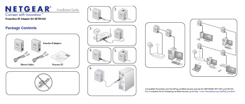
Installation GuideCompatible Powerline and HomePlug certified devices include the NETGEAR XET1001 and XE104. For a complete list of Homeplug certified devices, go to /certified_products .123456Powerline 85 Adapter Kit XETB1001Package ContentsPowerline 85 AdaptersEthernet Cables Resource CDAugust 2010This symbol was placed in accordance with the European Union Directive 2002/96 on the Waste Electrical and Electronic Equipment (the WEEE Directive). If disposed of within the European Union, this product should be treated and recycled in accordance with the laws of your jurisdiction implementing the WEEE Directive.©2010 by NETGEAR, Inc. All rights reserved. NETGEAR and the NETGEAR logo are registered trademarks of NETGEAR, Inc. in the United States and/or other countries. Other brand and product names are trademarks or registered trademarks of their respective holders. Information is subject to change without notice.LED and Button DescriptionsEthernet portPowerline LEDPower LEDPowerline LEDEthernet LEDUsing the Power ButtonThe Powerline Adapter’s normal state is power on mode. When you first plug it into an electrical outlet, it will be in power on mode.To power it off, push the button. When the power is off, the Power LED turns amber. Pressing the button again returns it to power on. You can also unplug and plug in the adapter to restore it to power on.Troubleshooting TipsSafety Information• AC input: 100-240V~, 100mA • Operating temperature: 0C~40C• The socket-outlet shall be installed near the equipment and should be easilyaccessible.Technical SupportThank you for selecting NETGEAR products.After installing your device, locate the serial number on the label of your product and use it to register your product at /register . Registration is required before you can use the telephone support service. Registration via the NETGEAR website is strongly recommended.Go to for product updates and Web support .For additional information about setting up, configuring, and using your Powerline 85 Adapter Kit, see the User Manual .For complete DoC please visit the NETGEAR EU Declarations of Conformity website at: /app/answers/detail/a_id/11621/。
ICS-85 86 手枪说明书
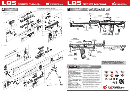
2-1裝BB彈方式Load BBs將彈匣上蓋依箭頭方向推開再倒入BB彈。
Open the cover to load BBs.建議使用 6mm BB彈。
6mm caliber BBs are recommended for optimum performance.依箭頭方向旋緊彈匣底下旋鈕,即可將BB彈順利送出。
To charge BB feed spring, please rotate the gear under the magazine.2-2裝卸彈匣Magazine Loadingand Unloading1.直接將彈匣插入彈匣插槽。
2.按壓退彈匣鈕即可將彈匣卸下。
1. Load the magazine directly into the magazine slot.2. Press the magazine catch to unload the magazine.2彈匣使用方式Magazine Attachment3可動部的說明Movable Parts1.將腳架固定板往後拉。
2.手抓住腳架使之併齊。
3.將腳架兩卡勾裝進護木上的定位孔。
4.放開固定板以收合腳架。
1. Pull the bipod releasing plate.2. Grab the bipod to align them together.3. Insert the hook on the stands into the positioning hole under the handguard.4. Release the releasing plate to store the bipod.1.將腳架固定板往後拉。
2.手抓住腳架使之併齊。
3.將腳架脫離護木定位孔。
4.放開腳架,腳架即可自然打開完成部署。
1. Pull the bipod releasing plate.2. Grab the bipod to align them together,3. Remove the stands from the positioning hole under the handguard.4. The bipod will be deployed automatically once you released it.3-1L86腳架調整L86 Store Bipod腳架收合To store the Bipod腳架佈署To deploy the Bipod3-2彈簧簧力調整Spring Adjustment1.將彈簧固定結合銷拉出。
英文安装说明书[1]
![英文安装说明书[1]](https://img.taocdn.com/s3/m/cb8afdda240c844769eaeefc.png)
2.4The mutual inductor secondary lines draw out with the4m㎡polyvinyl-chloride baling wire ,Is convenient for the wiring, gets "S1" on the wiring ear, "S2", "S3" and so on the mark..
2.5The entire mutual inductor soaks the insulating paint after the seasoning, after but dries, by guards against is affected with damp.
3.Techical Date
2.3On the post mutual inductor has the data plate and the polar symbol sign,symbolized on the sign the sign has "on" the inscription."On" indicated primary current in the mutual inductor the direction,Namely the expression works as when primary current by "on" end inflow, the secondary current then flows out from the S1 end after exterior load return route flows in the S2 end (or S3, S4, S5 end) .
C站JUE-85中文操作说明书 07-9-10
明进行了简单的翻译。如有不详之处,请参考原英文说明书,以原厂家英文说明书为准。
美特顿198534产品说明书

Eaton 198534Eaton Moeller® series Rapid Link - Reversing starter, 6.6 A,Sensor input 2, 230/277 V AC, AS-Interface®, S-7.A.E. for 62modules, HAN Q5, with manual override switchAllgemeine spezifikationEaton Moeller® series Rapid LinkReversing starter198534120 mm270 mm220 mm1.8 kg RoHSUL 60947-4-2CCCUL approvalIEC/EN 60947-4-2CEAssigned motor rating: for normal internally and externally ventilated 4 pole, three-phase asynchronous motors with 1500 rpm at 50 Hz or 1800 min at 60 Hz 4015081964093RAMO5-W202A32-512RS1Product Name Catalog NumberProduct Length/Depth Product Height Product Width Product Weight CertificationsCatalog Notes EANModel CodeParameterization: drivesConnect mobile (App) Parameterization: drivesConnectParameterization: FieldbusParameterization: KeypadDiagnostics and reset on device and via AS-InterfaceThermo-clickTwo sensor inputs through M12 sockets (max. 150 mA) for quick stop and interlocked manual operationManual override switchKey switch position HANDKey switch position AUTOElectronic motor protectionShort-circuit releaseThermistor monitoring PTCKey switch position OFF/RESETFor actuation of motors with mechanical brakeExternal reset possibleTemperature compensated overload protection CLASS 10 AIP65NEMA 12Class A10,000,000 Operations (at AC-3)10,000,000 Operations (at AC-3)Reversing starter0.3 A6.6 AIIIMotor starterASIAS-Interface profile cable: S-7.4 for 62 modules4000 VAC voltageCenter-point earthed star network (TN-S network) Phase-earthed AC supply systems are not permitted.Reversing starterDCFeatures Fitted with: Functions ClassDegree of protectionElectromagnetic compatibility Lifespan, electricalLifespan, mechanicalModelOverload release current setting - min Overload release current setting - max Overvoltage categoryProduct categoryProtocolRated impulse withstand voltage (Uimp) System configuration typeTypeVoltage typeVertical15 g, Mechanical, According to IEC/EN 60068-2-27, 11 ms, Half-sinusoidal shock 11 ms, 1000 shocks per shaftResistance: 10 - 150 Hz, Oscillation frequencyResistance: 6 Hz, Amplitude 0.15 mmResistance: 57 Hz, Amplitude transition frequency on accelerationResistance: According to IEC/EN 60068-2-6Max. 2000 mMax. 1000 mAbove 1000 m with 1 % performance reduction per 100 m -10 °C55 °C-40 °C70 °C< 95 %, no condensationIn accordance with IEC/EN 501780.3 - 6.6 A, motor, main circuit Adjustable, motor, main circuit6.6 A (at 150 % Overload)Maximum of one time every 60 seconds380 - 480 V (-15 %/+10 %, at 50/60 Hz)20 - 35 ms20 - 35 ms50/60 HzAC-53a 3 HP≤ 0.6 A (max. 6 A for 120 ms), Actuator for external motor brake230/277 V AC -15 % / +10 %, Actuator for external motor brake10 kA0 AType 1 coordination via the power bus' feeder unit, Main circuitMounting position Shock resistance Vibration AltitudeAmbient operating temperature - min Ambient operating temperature - max Ambient storage temperature - min Ambient storage temperature - max Climatic proofingCurrent limitationInput currentMains switch-on frequency Mains voltage tolerance Off-delayOn-delayOutput frequency Overload cycleRated frequency - min Assigned motor power at 460/480 V, 60 Hz, 3-phaseBraking currentBraking voltageRated conditional short-circuit current (Iq)Rated conditional short-circuit current (Iq), type 2, 380 V, 400 V, 415 VShort-circuit protection (external output circuits)47 Hz63 Hz6.6 A6.6 A0.09 kW3 kW0 kW3 kW400 V AC, 3-phase 480 V AC, 3-phase 50/60 Hz, fLN, Main circuit AC voltageCenter-point earthed star network (TN-S network) Phase-earthed AC supply systems are not permitted.0 V0 V0 V0 V0 V0 V24 V DC (-15 %/+20 %, external via AS-Interface® plug) 230/277 V AC (external brake 50/60 Hz)Connections pluggable in power section Specification: S-7.A.E. (AS-Interface®)Max. total power consumption from AS-Interface® power supply unit (30 V): 190 mANumber of slave addresses: 62 (AS-Interface®)010 m, Radio interference level, maximum motor cable lengthMeets the product standard's requirements.Meets the product standard's requirements.Rated frequency - max Rated operational current (Ie) at 150% overload Rated operational current (Ie) at AC-3, 380 V, 400 V, 415 V Rated operational power at 380/400 V, 50 Hz - min Rated operational power at 380/400 V, 50 Hz - max Rated operational power at AC-3, 220/230 V, 50 Hz Rated operational power at AC-3, 380/400 V, 50 Hz Rated operational voltage Supply frequencySystem configuration type Rated control supply voltage (Us) at AC, 50 Hz - min Rated control supply voltage (Us) at AC, 50 Hz - max Rated control supply voltage (Us) at AC, 60 Hz - min Rated control supply voltage (Us) at AC, 60 Hz - max Rated control supply voltage (Us) at DC - min Rated control supply voltage (Us) at DC - max Rated control voltage (Uc)ConnectionInterfacesNumber of auxiliary contacts (normally closed contacts)Number of auxiliary contacts (normally open contacts)Cable length10.2.2 Corrosion resistance10.2.3.1 Verification of thermal stability of enclosuresMeets the product standard's requirements.Meets the product standard's requirements.Meets the product standard's requirements.Does not apply, since the entire switchgear needs to be evaluated.Does not apply, since the entire switchgear needs to be evaluated.Meets the product standard's requirements.Does not apply, since the entire switchgear needs to be evaluated.Meets the product standard's requirements.Does not apply, since the entire switchgear needs to be evaluated.Does not apply, since the entire switchgear needs to be evaluated.Is the panel builder's responsibility.Is the panel builder's responsibility.Is the panel builder's responsibility.Is the panel builder's responsibility.Is the panel builder's responsibility.The panel builder is responsible for the temperature rise Generationentausch RA-SP zu RASP4.0Generation change from RA-MO to RAMO 4.0 Generationenwechsel RA-SP zu RASP5Generation change from RA-SP to RASP 4.0Generation change RAMO4 to RAMO5Elektromagnetische Verträglichkeit (EMV)Anschluss von Frequenzumrichtern an GeneratornetzeFirmware Update RASP 4.0Generationentausch RAMO4 zu RAMO5Generationswechsel RASP4 zu RASP5Generation Change RASP4 to RASP5Configuration to Rockwell PLC Rapid Link 5Configuration to Rockwell PLC for Rapid Link Generationentausch RA-MO zu RAMO4.0Generation Change RA-SP to RASP5MN040003_DEMN034004_DERapid Link 5 - brochureDA-SW-drivesConnect - installation helpDA-SW-USB Driver DX-COM-STICK3-KITDA-SW-drivesConnectDA-SW-Driver DX-CBL-PC-3M0DA-SW-drivesConnect - InstallationshilfeDA-SW-USB Driver PC Cable DX-CBL-PC-1M5Material handling applications - airports, warehouses and intra-logistics ETN.RAMO5-W202A32-512RS1.edzIL034084ZUDE | Rapid Link 5Sortimentskatalog Antriebstechnik-DE10.2.3.2 Verification of resistance of insulating materials to normal heat10.2.3.3 Resist. of insul. mat. to abnormal heat/fire by internal elect. effects10.2.4 Resistance to ultra-violet (UV) radiation10.2.5 Lifting10.2.6 Mechanical impact10.2.7 Inscriptions10.3 Degree of protection of assemblies10.4 Clearances and creepage distances10.5 Protection against electric shock10.6 Incorporation of switching devices and components10.7 Internal electrical circuits and connections10.8 Connections for external conductors10.9.2 Power-frequency electric strength10.9.3 Impulse withstand voltage10.9.4 Testing of enclosures made of insulating material10.10 Temperature rise Anmerkungen zur AnwendungBenutzerhandbücherBroschüreneCAD model Installationsanleitung InstallationsvideosKatalogeEaton Konzern plc Eaton-Haus30 Pembroke-Straße Dublin 4, Irland © 2023 Eaton. Alle Rechte vorbehalten. Eaton ist eine eingetrageneMarke.Alle anderen Warenzeichen sindEigentum ihrer jeweiligenBesitzer./socialmediacalculation. Eaton will provide heat dissipation data for thedevices.Is the panel builder's responsibility. The specifications for the switchgear must be observed.Is the panel builder's responsibility. The specifications for the switchgear must be observed.The device meets the requirements, provided the information in the instruction leaflet (IL) is observed.ramo5_v10.dwgramo5_v10.stpeaton-bus-adapter-rapidlink-reversing-starter-dimensions-002.eps eaton-bus-adapter-rapidlink-speed-controller-dimensions-003.eps eaton-bus-adapter-rapidlink-speed-controller-dimensions-002.eps eaton-bus-adapter-rapidlink-reversing-starter-dimensions-003.eps10.11 Short-circuit rating10.12 Electromagnetic compatibility 10.13 Mechanical function mCAD model Zeichnungen。
2.INMARSAT-C JUE85站操作说明
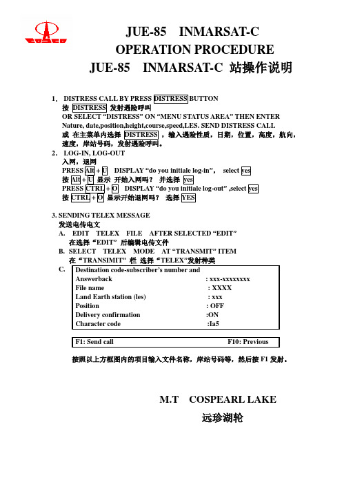
1. DISTRESS CALL BY PRESS DISTRESS BUTTON 按 DISTRESS 发射遇险呼叫 OR SELECT “DISTRESS” ON “MENU STATUS AREA” THEN ENTER Nature, date,position,height,course,speed,LES. SEND DISTRESS CALL 或 在主菜单内选择 DISTRESS ,输入遇险性质,日期,位置,高度,航向, 速度,岸站号码,发射遇险呼叫。 2. LOG-IN, LOG-OUT 入网,退网 PRESS Alt + U DISPLAY “do you initiale log-in”, select yes 按 Alt + U 显示 开始入网吗? 并选择 yes PRESS CTRL + O DISPLAY “do you initiale log-out” ,select yes 按 CTRL + O 显示开始退网吗? 选择 YES 3. SENDING TELEX MESSAGE 发送电传电文 A. EDIT TELEX FILE AFTER SELECTED “EDIT” 在选择“EDIT” 后编辑电传文件 B. SELECT TELEX MODE AT “TRANSMIT” ITEM 在“TRANSIMIT” 栏 选择“TELEX”发射种类 C. Destination code-subscriber’s number and Answerback : xxx-xxxxxxxx File name : XXXX Land Earth station (les) : xxx Position : OFF Delivery confirmation :ON Character code :Ia5 F1: Send call F10: Previous
- 1、下载文档前请自行甄别文档内容的完整性,平台不提供额外的编辑、内容补充、找答案等附加服务。
- 2、"仅部分预览"的文档,不可在线预览部分如存在完整性等问题,可反馈申请退款(可完整预览的文档不适用该条件!)。
- 3、如文档侵犯您的权益,请联系客服反馈,我们会尽快为您处理(人工客服工作时间:9:00-18:30)。
RADOME
Compass safe distance Standard compass: 0.1m Steering compass : 0.1m
INMARSAT-C EME
MODEL NAF-741GM SERIAL NO.
MADE IN JAPAN
<Type2>
WA R N I N G
Do not turn on the terminal under the primary power except the specific voltage (mentioned below).The primary power except the specific voltage may cause fire, electrical shock or malfunction. DC+24V(+19.2 V to +31.2 V) (When standard PSU, NBD-843A is used)
• Your communication data are transmitted via Inmarsat system and other global communications system, so unusually some errors may occur in communication theory same as the landlines. You are recommended to backup for your important data.
INMARSAT-C
MODEL JUE-85 SERIAL NO. DATE
IME
MODEL MASS
NTF-781GM 1.3kg
MADE IN JAPAN R 001VZAA1011
危険 D A N G E R
このカバーをはずすな 感電の恐れあり HIGH VOLTAGE DO NOT REMOVE THE COVER
This symbol denotes that improper handling poses a risk of causing injury or damage to the product and/or assets.
Example of symbols
The △ symbol denotes DANGER, WARNING or CAUTION. The inside illustration of the △symbol denotes meaning of the DANGER, WARNING or CAUTION more concretely. (This example warns of possible electrical shock.)
JUE-85
INMARSAT-C MOBILE EARTH STATION
INSTALLATION MANUAL
CODE NO. 7ZPSC0191
PREFACE
Thank you for purchase of the JRC Inmarsat-C, Mobile Earth Station, JUE-85. *Please read this Installation manual carefully and carry out proper installation. *Please keep the manual importantly to refer when it is necessary. *Please use it when questions and troubles are caused in installation, by any chance.
• Specifications of JUE-85 and its accessories may change without notice for improvement.
ii
BEFORE INSbols
This manual and the terminal are indicated the following safety symbols for your correct operation to prevent your and somebody’s injury or damage to the product and assets. The symbols and descriptions are as follows. You should understand well them before reading this manual and operating the terminal.
DANGER
Do not touch any internal parts with your hands or tools to avoid danger of electronic shock.
The lithium battery is built into JUE-85 (EME). Do not short-circuited of the terminal, do not give the high impact, and wet it to water. Those actions are dangerous against explosion.
• There is possibility that some functions of the terminal may not operate correctly depend on the hardware and software version of equipment connected to the terminal. Please confirm your equipment version before contact with the dealer or agent you purchased or JRC branches.
Do not approach the JUE-85(EME) while transmitting, It transmits microwave and strong microwave might be cause injury.
If a foreign substances, such as metal fragment, water, liquid and etc., are get into your JUE-85, turn off the power and contact with the agent you purchased or JRC branches. Continuous operation may cause fire, electrical shock or malfunction.
Technological, standard agreement proof and attestation number issued by Telecom Engineering Center Foundation in Japan.
iv
CAUTIONS DURING INSTALLATION
DANGER WARNING CAUTION
This symbol denotes that improper handling poses a high risk of causing death or serious injury.
This symbol denotes that improper handling poses a risk of causing death or serious injury.
IMPORTANT
Compass safe distance Standard compass: 0.2m Steering compass : 0.1m
Notes
R 001VZAA1011
Attestation number which means safe, high-quality product and suits EU instruction (Free circulation was permitted in the EU signatory).
The symbol denotes prohibited action. The inside illustration of the symbol denotes the specific prohibited action more concretely. (This example indicated disassembly is prohibited.)
CAUTIONS DURING INSTALLATION
WARNING
Do not bring JUE-85(EME) close to the fire, or put it in the fire. It causes the explosion, generation of heat, and the ignition of a built-in lithium battery.
The ● symbol denotes obligatory operation or instruction. The inside illustration of the ● symbol denotes obligatory operation or instruction more concretely. (This example indicates unplugging is the obligatory instruction.)
i
ATTENTIONS BEFORE USING
• JRC cannot accept responsibility for any loss due to incorrect operation, malfunction and other causes except product guarantee condition and liability by law.