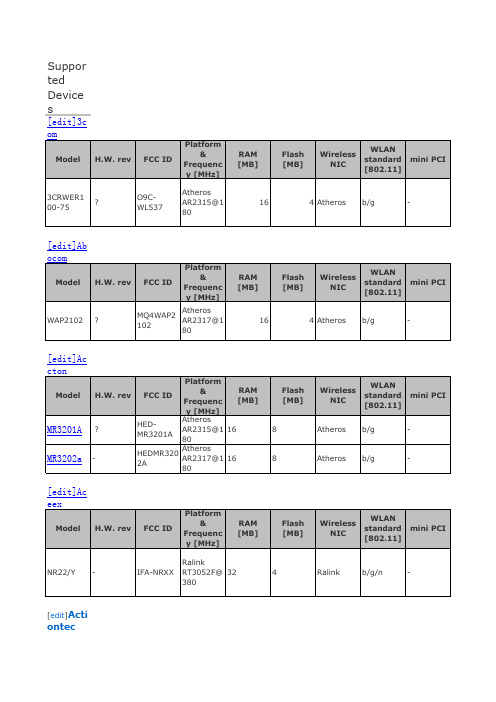
RD6400-ETH WALL ADAPTER PCB SCHEMATIC
讯飞网维 信号特克 千兆以太网性能测试仪 说明书

SIGNAL TEK™Cable Performance T esterI Gigabit PerformanceQualification – Test toIEEE 802.3 standardsI Selectable PerformanceT esting – qualify performanceof Data, Voice over IP, andIP Video applicationsI Performs Gigabit Ethernetlink establishment test in10 secondsI Data Monitoring to detectintermittent network problemsI Smart Autotest Functiondetects the presence of theSIGNAL TEK remote, activenetwork device or open endedcable and automatically runsthe appropriate test suiteI Intuitive Graphical UserInterface for fast andeasy operationI Internal and USBData Storage –store 20,000 tests internallyor unlimited on USB driveI Prints Easy-to-Read Pass/Fail Qualification ReportsSIGNALTEK™– High-Performance Gigabit Ethernet TestingSIGNALTEK™is the most cost-effective Gigabit Ethernet cableAutotest key to initiate tests from the remote end for one personoperation2.8Љ(7.1cm) 1⁄4VGA Color Display with backlighting for use in low light conditionMulti-color LEDs indicate link status,loopback mode,10/100 and Gigabit device detection,Autotest pass/fail,and battery conditionEasy-to-navigate user interfaceCompact design and soft over-mold sides fit well into any sized handContext sensitive softkeysSingle button cable testingQuick navigation key returns to Job Manager screenSingle button push for active network testing and monitoring Port status function detects 10/100 or Gigabit Ethernet devicesDisplays result for last autotest via red or green LED indicationSIGNAL TEK ™Standard KitCatalog No. 33-974I1 SIGNALTEK ™Near-end and remote-end handset IDEAL INDUSTRIES, INC.03/06Printed in U.S.A.ISO 9001:2000 QMSNo. 33-974SIGNALTEK ™OptionalPower Adapter – 4010-00-0136DESCRIPTION CAT NUMBER SIGNALTEK™ Cable Performance Tester 33-974Replacement cable accessory kit –Contains all original cables in SIGNALTEK™ kit 1219-91-0003RJ45 to 8 head alligator clipK-7920OPTIONALUniversal (120-240V) AC-DC power adapter (1)4010-00-0136。
单片机及电子技术英语常用词翻译手册

Glossarypattern: 模板Example: Pattern: QTP, SQTP, code or special requirements (blank otherwise). QTP Pattern #301.shunt regulator: 并联稳压器Example: Internal shunt regulator allows 12, 24, 48V operation.shift: 平移Example: The voltage at this pin shifts the output voltage.slew rate[1] 压摆率n.Example: The slew rate (SR) is defined as the maximum rate of change of the output on an op amp. [2] 斜率,边沿斜率,变化率n. (需请教资深工程师)Example: Slew rate control is disabled for Standard Speed mode.(1和2意义相同,都是指“电压转换速率-单位时间内的电压变化率dv/dt”这个词的译法很多,压摆率,斜率,转换率,回转率,斜升率等,几乎没有个标准,不必计较太多。
我建议译成“转换率”。
wiper[1] 滑动端n.Example: The digital potentiometer IC has 64 wiper positions.[2] 雨刷n.Example: Rain sensor switches off much too late, leaving the wipers rubbing a dry window.wiper resistance: 滑动电阻Example: Wiper resistance of the digital pot is proportional to VIN.passive[1] 无源adj.Example: Components incapable of controlling current by means of another electrical signal are called passive devices.[2] 被动adj.Example: This manual describes a Passive Keyless Entry (PKE) system upgrade to an existing Remote Keyless Entry (RKE) application.transponder 应答器n.Example: The transponder key fob operates as a standard 5-button RKE fob, when not being challenged by a Low-Frequency Initiator signal.Schematics[1] 原理图n.Example: A simplified schematic of one analog input circuit, with a detailed explanation of how it works.[2] 示意图n.socket[1]插座n.Example: Through interchangeable programming socket modules, MPLAB PM3 enables you to quickly and easily program the entire line of Microchip microcontroller devices.[2]套接字n.Example: Compile-time check is done to make sure that enough sockets are available for selected TCP applications.stack[1]堆栈n.Example: The 16th working register (W15) operates as a software Stack Pointer for interrupts and calls.[2]协议栈n.Example: You can use the Microchip Stack for the ZigBee protocol provided in this application note to quickly build your application.halt 暂停v.Example: After a successful build, the Run icon becomes blue, indicating that the program is halted and ready to run.mistype 输入错误,错误输入v. & n.Example: After a successful build, the Run icon becomes blue, indicating that the program is halted and ready to run.procedural abstraction过程抽象Example: The procedural abstraction optimization can be performed more than once.Linker Script链接描述文件Example: Right click on Linker Scripts in the project window and add the linker script file, 18F452.lkr.simulator软件模拟器n.Example: Covers the MPLAB IDE setup for use with MPLAB C18 using MPLAB projects and MPLAB SIM simulator, and references the basics of MPLAB IDE configuration for running the examples and applications in this guide.Serial Quick Turn Programming带序列号的快速批量编程Example:Serial Quick Turn Programming (SQTP) allows you to program a unique serial number into each device. This number can be used as an entry code, password or ID number.disassemble反汇编v.Example: You can view the Program Memory as hex code, machine code or disassembled with symbols (if available).Serial number 序列号n.Example: Use Serial Quick Turn Programming (SQTP) to program a unique serial number into each device.splash screen闪屏n.Example: The system performs a self-check, briefly displays the splash screen, then the versions, followed by the MPLAB PM3 Main menu.Inline assemble行内汇编n.adapter适配器n.Example: Since MPLAB PM3 has ICSP built-in, you cannot use the PRO MATE II ICSP Socket Module (AC04004) and the MPLAB PM3-to-PRO MATE II device adapter.Wall adapter电源适配器n.Plug-in[1]插件n.Example: MPLAB Visual Device Initializer is an MPLAB plug-in and can be installed independently of MPLAB IDE.[2]接插n.Example: The various dsPIC33F development boards may use the plug-in modules for the dsPIC33F silicon devices.bond wire绑定线n. (芯片内部连接裸片和封装引脚的线)Example: The MCP1727 also has an output voltage sense feedback pin that is used for bond wire compensation.sample[1] 采样v./n.Example: The MCP3550-50 (50 Hz rejection) has a sample rate of 12.5 samples per second (sps). [2] 样片n.Example: All four members of the PIC18F45J10 series are available now for engineering samples. [3] 示例n.Example: sample program, sample codetuning fork type crystal音叉式晶振n.Example: This mode is best suited to drive resonators with a low drive level specification, for example, tuning fork type crystals.Loop filter 环路滤波器n.Assert 使…有效v. (建议根据上下文灵活翻译)[1] 拉低v. (“拉低”还是“拉高”要依照时序图判断,本例中SCLx是低电平有效)Example: Therefore, the CKP bit will not assert the SCLx line until an external I2C master device already asserted the SCLx line.[2] 输出v.Example: A stop bit is asserted on the SDA pin at the end of a receive/transmit by setting the Stopsequence enable bit, PEN (SSPCON2<2>).[3] 发出v.Example: The reason that bus collision is not a factor during a START condition is that no two bus masters can assert a START condition at the exact same time.Deassert 使…无效v. (建议根据上下文灵活翻译)[1] 拉高v. (“拉低”还是“拉高”要依照时序图判断,本例中SCL是低电平有效)Example: The SCL output will remain low until the CKP bit is set and all other devices on the I2C bus have deasserted SCL.Upper byte 最高字节;high byte 高字节;low byte 低字节Charge pump 电荷泵n.Power device 功率器件n.Example:The programmable dead-band delay can be used to prevent shoot-through current in half-bridge power devices.Endpoint端点n.Example: USTAT contains the transfer endpoint number, direction and ping-pong buffer pointer value (if used).Suspend Mode 挂起模式,暂停模式n. (需请教资深工程师)赞成:挂起模式Example: Once an Idle state is detected, the user may want to place the USB module in Suspend mode.Ping-pong buffer 乒乓缓冲器n. (第一次出现时,译为:乒乓(ping-pong)缓冲器)Packet Transfer 数据包传输n.Single-ended Zero 单端0 n.Example: The USB Control register contains a status bit, SE0 (UCON<5>), which is used to indicate the occurrence of a single-ended zero on the bus.Buffer Descriptor 缓冲器描述符n.Example: The BDT is composed of Buffer Descriptors (BD) which are used to define and control the actual buffers in the USB RAM space.Token[1] 令牌n.Example: The SIE will send an ACK token back to the host to Acknowledge receipt, however.[2]标记n.Example: Break a string into substrings, or tokens,by inserting null characters in place of specified delimiters.Strobe 选通n.Example: In addition, the SPP can provide time multiplexed addressing information along with the data by using the second strobe output.Transaction 事务n.Example: The wait states are added symmetrically to all transactions.Isochronous 等时,同步adj. (需请教资深工程师)赞成同步的Example: This is ideal for applications that require isochronous, large volume data movement.Starter Kit 入门工具包n.Eye Pattern 眼图n.Example: These bits control output enable state monitoring and eye pattern generation.Data Toggle Synchronization 数据Toggle同步n. (需请教资深工程师)toggle是翻转(乒乓)开关的意思,就是按一下是开,再按是关,然后往复……也可以是指IO输出高低的变换,等。
华硕主板

数字家庭主板M2NDH-支持AMD®SocketAM2Athlon64FX/Athlo64X2/Athlon64/Sempron -AMDLive!™Ready-强大扩充能力:1xPCI-Ex16、2xPCI-E、3xPCI-华硕WiFi-APSolo-华硕DHRemote™-华硕MP3-In™-华硕Q-Connector-高保真音频中央处理器支持AMD®SocketAM2Athlon64FX/Athlo64X2/Athlon64/Sempron 支持AMDCool'n'Quiet™技术AMD64架构,同时兼容32位和64位计算AMDLive!™Ready芯片组NVIDIAnForce®430MCP前端总线2000/1600MT/s内存双通道内存架构4x240-pinDIMM内存插槽,支持最大容量高达8GB的DDR2800/667/533ECC和non-ECC、un-buffered内存扩充插槽1xPCI-Expressx16插槽2xPCI-Expressx1插槽3xPCI2.2插槽存储装置/RAID-1xUltraDMA133/100/66/33-4xSerialATA3.0Gb/s-NVIDIAMediaShield™RAID通过SerialA TA设备支持RAID0、1、0+1、5和JBOD网络功能NVIDIAnForce®430内建GigabitMAC,支持externalAttansicPHY无线局域网:54MbpsIEEE802.11b/g(华硕WiFi-APSolo)音频功能ADI6声道高保真音频CODEC背板S/PDIF数字音频输出USB高达8个USB2.0/1.1接口M2N-VMDH-AMDSocketAM2-NVIDIAGeForce6100/nForce430-双通道DDR2800/667/533-1xPCIExpressx16+1xPCIExpressx1+2xPCI-双VGA:DVI-D和D-Sub-8声道高保真音频-2x1394a接口中央处理器支持AMD®SocketAM2Athlon64X2/Athlon64FX/Athlon64/Sempro nAMDCool'n'Quiet™技术AMD64架构,兼容32位和64位计算AMDLive!™Ready芯片组NVIDIAGeForce6100/nForce430前端总线2000/1600MT/s 内存双通道内存架构4x240-pinDIMM插槽,支持最大容量为8GB的DDR2800/667/533non-ECC,un-buffered内存显卡集成GeForce6100GPU高清晰视频处理,最高分辨率可达1920x1440(@75Hz)支持RGB显示;UXGA1600x1200(@60Hz)支持DVI-D显示支持双VGA输出:DVI-D和RGB注意:DVI-D不能用来输出RGB信号至CRT。
MSI 迪贝尔 GAMING电脑主机说明书

Generated 2023-06-30, check for the latest version /datasheet. The information provided in this document is intended for informational purposes only and is subject to change without notice.
LAN
Realtek® RTL8111H
Cooling System
Liquid Cooling (For AMD Ryzen™ 7 5800X Processor) Air Cooling
Volume
40 Liter
Dimension (WxDxH来自 195 x 514.8 x 466 mm (mm)
© 2023 Micro-Star Int'l Co.Ltd. MSI is a registered trademark of Micro-Star Int'l Co.Ltd. All rights reserved.
out
Combo port
7. 1x USB 3.2 Gen 2x2 Type C / 1x 6. 2x USB 3.2 Gen 1 Type A / 2x USB 3.2 Gen 2 Type A / RJ45 (2.5G USB 2.0 Type A
LAN)
8. 2x WiFi Antenna
9. 6x Audio jacks
I/O (Rear)
4 x USB 3.2 Gen1 Type A 2x USB 2.0 Type A 2x PS/2 port 1x DVI-D out 1x HDMI™ (supports 4K @24Hz as specified in HDMI 1.4b) 1x RJ45 (1GLAN) 3x Audio jacks
德尔网络Z9000产品说明说明书

Highly-available, high-performance Active Fabric spineThe Dell Networking Z9000 is a high-performance, efficient switch-router product designed to meet the requirements for high density 10/40GbE aggregation in a data center core network. The Z9000 switch is designed to address the East/West traffic patterns of modern data centers, providing higher performance and bandwidth across the data center for server to server communications. The Z9000 fabric switch can support 32 ports of 40GbE QSFP+ or 128 ports of 10GbE SFP+ realized through breakout cables. Supporting a full suite of Ethernet switching and routing protocols in the hardened Dell Networking OS, the Z9000 fabric switch can enable an Active Fabric™ via Layer 2 or Layer 3 protocols.An Active Fabric design with Z9000 switches can be built outto create scalable, high-performance 10/40GbE data center networks. The resiliency of an Active Fabric is superior to legacy, centralized core architectures, since the failure of a single node within a CLOS network cannot bring down the entire switching fabric. A single switching element can be restarted or replaced in the event of a failure versus an entire chassis reboot required in a centralized design.The Z9000 is supported with Active Fabric Manager (AFM), which helps automate design and deployment of multi-tier fabrics. AFM helps customers manage multiple fabrics from a single console, enabling a unified view of the entire fabric, when combinedwith Dell OMNM and other management solutions. With AFM, over 25 templates can be customized for specific workloadand deployment scenarios, easily delivering active-active L2or L3 designs for 1/10/40G with Z9000 to rack (with top-of-rack switches including Dell S4810/S4820T, S6000) and blade infrastructures (including Dell MXL).Key applications• Containerized data centers and prover-hosted data centers• Enterprise DC core aggregating 10/40GbE, cloud computing, high-performance cores• High-performance SDN/OpenFlow 1.0 enabled with ability to inter-operate with industry standard OpenFlow controllers Key features• 2RU high-density 10/40GbE fabric/core switch with 32 x 40GbE ports expandable to 128 x 10GbE ports using QSFP+ to SFP+ breakout cables• 2.5Tbps (full-duplex) non-blocking, fabric delivers line-rate performance under full load• Virtual link trunking (VLT) and enhanced VLT for layer 2 multipathing• Modular Dell Networking OS software delivers inherent stability as well as advanced monitoring and serviceability functions • Supported with Active Fabric design and Active Fabric Manager to reduce design, configuration and management for active/active deployments• Total aggregated packet buffer memory of 54MB for line-rate processing• 128 link aggregation groups with up to eight members per group, using advanced hashing with random seed values• Reversible front-to-back or back-to-front airflow• Supports jumbo frames for high-end server connectivity• Redundant, hot-swappable power supplies and fans• Low power consumption• Supports OpenFlow 1.0 in hybrid mode• Supports new QSFP+ PSM4, SR and ESR transceiver/cablesDell Networking Z9000Data center core fabric switchHigh-density 32-port 40GbE core router/switch in 2RU form factor; line rate, non-blocking, low-latency and lower power, enabling a greener, faster data center; feature-rich Dell Networking OS.High-performance,efficient fabric switchfor modern data centertraffic.© 2013 Dell, Inc. All rights reserved. Dell and the DELL logo are trademarks of Dell, Inc. All other company names are trademarks of their respective holders.Information in this document is subject to change without notice. Dell Inc. assumes no responsibility for any errors that may appear in this document.Learn more at /NetworkingNovember 2013 | Version 2.1dell-networking-Z9000-spec sheetSpecifications: Z9000 data center core switchProductZ9000, 32 x 40GbE QSFP+, 1 x AC PSU, 4 x Fans, I/O Panel to PSU AirflowZ9000, 32 x 40GbE QSFP+, 1 x AC PSU, 4 x Fans, PSU to I/O Panel AirflowZ9000, 32 x 40GbE QSFP+, 1 x DC PSU, 4 x Fans, I/O Panel to PSU AirflowZ9000, 32 x 40GbE QSFP+, 1 x DC PSU, 4 x Fans, PSU to I/O Panel AirflowRedundant power supplyZ9000, AC Power Supply, I/O Panel to PSU Airflow Z9000, AC Power Supply, PSU to I/O Panel Airflow Z9000, DC Power Supply, I/O Panel to PSU Airflow Z9000, DC Power Supply, PSU to I/O Panel Airflow OpticsTransceiver, QSFP+, 40GbE, SR Optics, 850nm Wavelength, 100–150m Reach on OM3/OM4Transceiver, QSFP+, 40GbE, ESR OpticsTransceiver, QSFP+, 40GbE PSM4 (2km reach), 1m, 5m, 15m Transceiver, QSFP+, 40GbE, LR4, 10Km reach CablesCable, 40GbE QSFP+, Active Fiber Optic, 10m, 50mCable, 40GbE QSFP+, Direct Attach Cable, 0.5m, 1m, 3m, 5m, 7m Cable, 40GbE MTP to 4xLC Optical Breakout Cable, 1m, 3m, 5m, 7m (optics not included)Cable, 40GbE QSFP+ to 4xSFP+, Direct Attach Breakout Cable, 0.5m, 1m, 3m, 5m, 7mCable, 40GbE MTP Fiber over OM3, 1m, 3m, 5m, 7m, 10m, 25m, 50m, (75m and 100m in 2014)Cable Management Kit, Z9000 MTP to LC (1RU 48-port LC)SoftwareDell Networking OS Software, Layer3Note: In-field change of airflow direction not supported.Physical32 line-rate 40 Gigabit Ethernet QSFP+ ports1 RJ45 console/management port with RS232 signaling 1 RJ45 10/100/1000 Base-T management port 1 x USB 2.0 type A storage port 1 x USB 2.0 type B console portSize: 2 RU, 3.48 x 17.32 x 24” (8.8 x 44 x 61 cm) (H x W x D)Weight: 39 lbs (1 power supply, 4 fan trays)Power supply: 100–240V AC 50/60 Hz, -40 to -60V DC Max. thermal output: 2692 BTU/h Max. current draw per system:8A at 100/120V AC, 4A at 200/240V AC 16.5A at -48V DCMax. power consumption: 789W Max. operating specifications:Operating temperature: 0°C to 40°COperating humidity: 10 to 85% (RH), non-condensing Max. non-operating specifications:Storage temperature: –40°F to 158°F (–40°C to 70°C)Storage humidity: 5 to 95% (RH), non-condensing Reliability: MTBF 135,744 hoursRedundancyHot swappable redundant power Hot swappable redundant fansPerformanceMAC addresses:128K IPv4 routes: 16KIPv6 routes:8K (shared cam space with IPv4)Switch fabric capacity: 2.56Tbps (full-duplex)Forwarding capacity 1.9BppsQueues per port: 8 COS queues L2 VLANs: 4096ACLs: 8K ingress, 4k egressLAGs:128 with up to 8 members per LAG LAG load balancing: Based on Layer 2, IPv4 headers Packet buffer memory:54MBIEEE compliance802.1AB LLDP802.1D Bridging, STP 802.1p L2 Prioritization 802.1Q V LAN Tagging, Double VLAN Tagging, GVRP 802.1s MSTP802.3ad Link Aggregation with LACP 802.3ae 10 Gigabit Ethernet (10GBase-X)802.3ba 40 Gigabit Ethernet (40GBase-SR4, 40GBase-LR4) on optical ports802.3uFast Ethernet (100BASE-TX) on manatement ports802.3x Flow Control Force10 PVST+MTU 12,000 bytesRFC and I-D ComplianceGeneral Internet protocols768 UDP 793 TCP 854 Telnet 959 FTP 1321 MD5 1350 TFTP 2474 Differentiated Services 3164 SyslogGeneral IPv4 protocols791 IPv4792 ICMP 826 ARP 1027 Proxy ARP 1035 DNS (client)1042 Ethernet Transmission 1191 Path MTU Discovery 1305 NTPv31519 CIDR 1812 Routers 1858 IP Fragment Filtering 2131 DHCP (relay)2338 VRRP 3021 31-bit Prefixes 3046 DHCP Option 823069 Private VLAN 3128 Tiny Fragment Attack ProtectionRIP1058 RIPv12453RIPv2OSPF2154 MD5 1587 NSSA 2328 OSPFv2 2370 Opaque LSA 2740 OSPFv3 4552 OSPFv3 IPsec authenticationBGP1997 Communities 2385 MD52439 Route Flap Damping 2796 Route Reflection 2842 Capabilities 2918 Route Refresh 3065 Confederations 4360 Extended Communities 4893 4-byte ASN 5396 4-byte ASN Representations 4271 BGPv42545 BGp.4 Multiprotocol Extensions for IPv6 Inter-Domain Routing Draft Graceful Restart Draft BGP Add PathMulticast1112 IGMPv1 2236 IGMPv23376 IGMPv3 3569 SSM for IPv44541 IGMP 4601PIM-SMSnoopingSDN/OpenflowOpenflow standard 1.0 with extensionsNetwork management1155 SMIv1 1156 Internet MIB 1157 SNMPv1General IPv6 protocols2460 IPv6 1858 IP FragmentFiltering 2461 Neighbor Discovery 2675 Jumbograms (partial) 3587 Global Unicast 2462 Stateless Address Address Format Autoconfiguration (partial) 4291 Addressing2463 ICMPv6 1981 IPv6 Path MTU 4861 IPv6 Host for Management DiscoveryPortIS-ISRFC 1195 Routing IPv4 with IS-IS RFC 5308 Routing IPv6 with IS-IS 2461 Neighbor Discovery1212 Concise MIB Definitions 1215 SNMP T raps 1493 Bridges MIB 1850 OSPFv2 MIB 1901 Community-Based SNMPv22011 IP MIB 2012 TCP MIB 2013 UDP MIB 2096 IP Forwarding Table MIB 2570 SNMPv32571 Management Frameworks 2572 Message Processing and Dispatching 2576 Coexistence Between SNMPv1/v2/v32578 SMIv22579 Textual Conventions for SMIv22580 Conformance Statements for SMIv22618 RADIUS Authentication MIB 2665 Ethernet-Like Interfaces MIB 2674 Extended Bridge MIB 2787 VRRP MIB 2819 RMON MIB (groups 1, 2, 3, 9)2863 Interfaces MIB 2865 RADIUS 3273 RMON High Capacity MIB 3416 SNMPv23418 SNMP MIB 3434 RMON High Capacity Alarm MIB 5060 PIM MIB ANSI/TIA-1057 LLDP-MED MIB draft-ietf-idr-bgp4-mib-06 BGP MIBv1IEEE 802.1AB LLDP MIB IEEE 802.1AB LLDP DOT1 MIB IEEE 802.1AB LLDP DOT3 MIB ruzin-mstp-mib-02 MSTP MIB (traps) sFlowv5 MIB (version 1.3)FORCE10-BGP4-V2-MIB F orce10 BGP MIB(draft-ietf-idr-bgp4-mibv2-05)FORCE10-IF-EXTENSION-MIB FORCE10-LINKAGG-MIBFORCE10-COPY-CONFIG-MIB FORCE10-PRODUCTS-MIB FORCE10-SS-CHASSIS-MIB FORCE10-SMIFORCE10-SYSTEM-COMPONENT-MIB FORCE10-TC-MIBFORCE10-TRAP-ALARM-MIBFORCE10-FORWARDINGPLANE-STATS-MIBRegulatory complianceSafetyUL/CSA 60950-1, Second EditionEN 60950-1, Second EditionIEC 60950-1, Second Edition Including all National Deviations and Group DifferencesEN 60825-1 Safety of Laser Products Part 1: Equipment Classification Requirements and User’s GuideEN 60825-2 Safety of Laser Products Part 2: Safety of Optical Fibre Communication Systems FDA Regulation 21 CFR 1040.10 and 1040.11EmissionsAustralia/New Zealand: AS/NZS CISPR 22: 2008, Class A Canada: ICES-003:2004, Class AEurope: EN 55022: 2006+A1:2007 (CISPR 22: 2008), Class A Japan: VCCI V-3/2010.04 Class AUSA: FCC CFR 47 Part 15, Subpart B:2011, Class AImmunityEN 300 386 V1.4.1:2008 EMC for Network EquipmentEN 55024: 1998 + A1: 2001 + A2: 2003EN 61000-3-2: Harmonic Current Emissions EN 61000-3-3: Voltage Fluctuations and Flicker EN 61000-4-2: ESDEN 61000-4-3: Radiated Immunity EN 61000-4-4: EFT EN 61000-4-5: SurgeEN 61000-4-6: Low Frequency Conducted ImmunityRoHSAll Z-Series components are EU RoHS compliant.CertificationsTAA (T rade Agreement Act) compliant models also available。
最全DD-WRT 支持无线路由器列表
Suppor ted Device s[edit]3c[edit]Ab [edit]Ac [edit]Ac [edit ]Actiontec[edit ]ADIEnginee [edit ]Airl[edit ]Airlive /[edit ]AlfaNetwor[edit ]Alln[edit]Ana ptyx Wireles sDynami[edit]Ara da System[edit]As[edit]Asu sWARNIN G: It is recomme nded to use ASUS Firmware restorati on tool for ASUS routers initial flash (use*.TRX file)[edit ]BelkinWARNING:Always use TFTP to flash Belkin routers if at allpossible!Upgradin g dd-wrt from the webinterface can lead to abricked (nonfunc tional)unit![edit]Bou[edit]Bro[edit]Buf[edit]Cisc o [edit]Cisc oLinksys[edit]Cisc o Linksys[edit]Cisc o Linksys (Wireles s[edit ]Cisc[edit ]Conceptron [edit ]Compex[edit]Co nrad Elektron[edit]Co[edit ]Dev[edit ]Digi[edit ]D-Link[edit]Do odle[edit]Dy[edit]Edi[edit]En [edit ]EnGeniusseeSenao[edit ]ExelNetwor[edit]Flui[edit]FO[edit]Fr y's Electron ics[edit]Ga[edit]Gat[edit]In tellinet (Reichel t)see RFNet Techn ologi es[edit ]Io[edit ]JJPl[edit ]Lanready[edit]Lin ksysseeCisco[edit ]Log[edit ]Ma[edit ]Mer[edit]Mi MN-700@125[edit ]Mikrotik Routerb[edit]Mi [edit]Mo[edit]MS[edit]MT N Electron[edit]Ne[edit]Net[edit]NET[edit]Net[edit]No[edit]Op enMesh[edit]Ope[edit]OS[edit ]Ovislinksee Airli ve[edit ]PC-[edit ]Planex aka[edit]Ra[edit ]Ray[edit ]Rep[edit ]RFNetTechnol[edit]Ro[edit ]Senao / EnGeni。
涂装设备英语词汇
conveyorchain and chain guide tracks 输送链和链条导轨 lower guide track conveyor chain Upper chain guide track skid lock 下层导轨 输送链 上层导轨 滑橇锁紧
automatic "on the fly"greaser 自动化同步油脂加注器 lubrication device (drop oiler) conveyor elements drip pan dip tank main gear box stand -by drive power rail link plates break force 润滑装置 机运部件 积液盘 浸槽 主齿轮箱 备用驱动 导电轨 链板 抗拉应力
内部宽度 轴衬 套筒滚轮 接油盘 连接板 分力梁 钢梁 防飞溅挡板 支撑栓 导向轮 摆杆框架 注油装置 桶料泵 油刷 低碳钢 不锈钢 主断路器 母线 控制面板照明
glazing cells windscreen and rear glass 前后风挡玻璃 hose package centring station primer bottle shaker nozzle cleaner double pump station safety equipment operation panel glass gluing cell muting sensors floor conveyor manual shift system technical availability primer bottle shaker front glass rear glass 管线包 对中单元 底涂摇晃仪 胶嘴清洁装置 双胶泵 安全设备 操作面板 玻璃涂胶项目 遮蔽传感器 地板输送链 手动 班次 使用率 底涂、中涂漆 前风挡 后风挡
SEA01常数电压与电流调节器在线数字裁剪评估板应用说明书
AN4604Application note Evaluation board for the SEA01 constant voltage and currentcontroller with online digital trimmingIntroductionThis application note describes a 65 W wide range input SMPS designed for use in adaptersfor typical hi-end portable computer power supplies.The design is based on the EVL6566B-65W-QR demonstration board from ST (ref.AN3089), with the principal difference located on the secondary side, where the SEA01digital constant voltage & current controller featuring online trimming replaces the constantvoltage & constant current (CV-CC) controller (TSM1014) found on the older board.The new board is therefore ideal for testing the features and benefits of the online digitaltrimming technology recently introduced by STMicroelectronics on the SEA01 controller.Since the EVL6566B-65W-QR and STEVAL-ISA161V1 boards are very similar, thisdocument will focus on the SEA01 and the new trimming feature. For a detailed descriptionand performance analysis of the complete board, please refer to AN3089.Figure 1. STEVAL-ISA161V1 evaluation boardOctober 2014DocID027047 Rev 11/16Contents AN4604 Contents1Main characteristics and circuit description . . . . . . . . . . . . . . . . . . . . . 31.1Power stage . . . . . . . . . . . . . . . . . . . . . . . . . . . . . . . . . . . . . . . . . . . . . . . . 31.2Closing the loop . . . . . . . . . . . . . . . . . . . . . . . . . . . . . . . . . . . . . . . . . . . . . 5 2Digital trimming operation . . . . . . . . . . . . . . . . . . . . . . . . . . . . . . . . . . . . 7 3Functional check . . . . . . . . . . . . . . . . . . . . . . . . . . . . . . . . . . . . . . . . . . . . 9 4Bill of material . . . . . . . . . . . . . . . . . . . . . . . . . . . . . . . . . . . . . . . . . . . . . 11 5Revision history . . . . . . . . . . . . . . . . . . . . . . . . . . . . . . . . . . . . . . . . . . . 152/16DocID027047 Rev 11 Main characteristics and circuit descriptionThe main characteristics of the power supply are:∙Input mains range: Vin: 90 ~ 264 Vrms; f: 45 ~ 66 Hz∙O/P voltage (CV mode): +19 Vdc ± 2% (native value), ± 0.1% (after trimming)∙O/P current (CC mode): 3.75 Adc ± 15% (native value), ± 1.67% (after trimming)∙Standby consumption: < 100 mW @ 230 Vac∙Average efficiency: greater than 89%∙EMI: in accordance with EN55022 - class B∙Safety: in accordance with EN60950∙PCB type: CEM-1, single side, 35 µm∙Board size: 58 x 121 mm, 25 mm maximum component heightstage1.1 PowerThe STEVAL-ISA161V1 features a quasi resonant (QR) flyback stage driven by the L6566Bcontroller. The converter implements peak current mode control, detecting thedemagnetization of the power transformer by sensing its auxiliary winding through theL6566B ZCD pin.The maximum switching frequency is set at approximately 165 kHz. If the load decreasesfurther, the system enters valley skipping mode: always turning the power MOSFET on withits drain valley voltage. For very light loads, the converter enters burst mode for themaximum efficiency.Approximately 150 V is selected for the reflected voltage to benefit from the small capacitiveturn-on losses associated with QR operation and still retain a good margin on the maximumbreakdown voltage of the power MOSFET.All the power components are thus selected according to the voltages and the output power.The converter also includes a brown-out circuit that senses the mains voltage before thebridge diodes, reducing power consumption and allowing fast restarts when latchedprotections are triggered.Finally, a fast discharge circuit is present on the output bus voltage to quickly discharge theoutput capacitors on circuit turn off under a no-load condition.The adapter has a full set of protection features, including output short-circuit, outputovervoltage, output diode short-circuit and board overtemperature.The converter has a modular configuration. All the power stage is housed on a motherboard(see schematic in Figure2) with a socket on the secondary side to accommodate a smalldaughterboard containing the CC-CV controller and the corresponding compensationnetworks.DocID027047 Rev 13/164/16DocID027047 Rev 1DocID027047 Rev 15/161.2 Closing the loopThe daughterboard on the secondary side of the STEVAL-ISA161V1 includes the SEA01:the latest CV-CC controller from STMicroelectronics. Besides the usual analog circuitry (two transconductance op-amps with their references), it includes a digital block that features an I²C interface, a redundant OTP (two OTP memories) and two digitally trimmable references for the two op-amps. The IC block diagram is shown in Figure 3.The SEA01 is housed on a small daughterboard which is mounted vertically on the main evaluation board. The schematic for the daughterboard is shown in Figure 4.The simple daughterboard includes the output voltage divider and the compensation for theCV section, the compensation for the CC section, the connector for the trimming interfacecable and a couple of small signal OR-ing diodes to select the higher supply voltagebetween the motherboard output voltage and the programming voltage supplied through J5.The device supply must be 17 V ≤ V CC≤ 20 V in order to correctly burn the OTP memory.On this demo board, the V CC is the output voltage of the adapter (minus one diode drop),and is therefore already in the correct range for burning.If the daughterboard is used in a lower out voltage application, the supply from pin 4 of J5 isused to provide the necessary voltage for the burning operation.The feedback loop component values are the same as those on the original board describedin AN3089.6/16DocID027047 Rev 12 Digital trimming operationThe aim of this board is to help demonstrate how the digital trimming operation works. Forthis reason, two trimming tools have also been developed:∙EVLUSB-TRIM is the simpler version with just a USB-I²C interface and a 19 V supply intended for manual operation.∙STEVAL-PCC019V1 is more functional, including three I²C interfaces with relevant 19 V supplies and an electronic load on the board. This tool allows for fully automated trimmingof the SMPS.In this document, we will refer to the first tool, EVLUSB-TRIM.It connects the SEA01 to a PC through an interface board and allows control of the trimmingoperation through a user-friendly Graphic User Interface (GUI). A detailed user manualprovided with the trimming tool explains how to setup the debug environment.Figure5 shows the complete setup environment for the trimming operation.86% WULPPLQJThrough the GUI, the EVLUSB-TRIM sends all the available commands to the SEA01. Thechanges in the STEVAL-ISA161V1 output can be monitored with a multimeter or anoscilloscope. The messages returned from the SEA01 can be easily read on the PC GUI.Figure6 shows an example Emulate Vrefv command with a 0.6% value. The I²C frame isacquired with an oscilloscope and decoded with the “Prodigy Solutions I²C Decode solution”software installed on the oscilloscope.This software greatly simplifies analysis of the data received (or sent) by SEA01.According to the I²C protocol, we can find the following sequential data:∙start bit∙I²C address∙r/w bit∙acknowledge bit∙1st data byte∙acknowledge bit∙2nd data byteDocID027047 Rev 17/168/16DocID027047 Rev 1∙acknowledge bit ∙stop bit In the example:∙I²C address = 0x52, correct SEA01 address∙1st data = 0x90, “Emulate Vrefv” command for SEA01∙2nd data = 0x06, +0.6% information with 1 bit parity checkFigure 6. “Emulate Vrefv + 0.6%” commandOnce the right set of values for both loops has been determined, the SEA01 can be burned and the trimming tool can be disconnected. At this point, the adapter functions like any other standard adapter, but with a very accurate output voltage and current.DocID027047 Rev 19/16AN4604Functional check3 Functional checkAs the board is very similar to the EVL6566B-65W-QR, all the functions are the same; onlya few aspects associated with the compensation network have been re-tested.First, the transient behavior was checked. Like in the AN3089, the most critical transition was tested with a setup having a maximum input voltage (i.e. 265 Vac) and maximum load swing (0 A to 3.42 A)The results are shown in Figure 7 and Figure 8.Also with this board, the transitions are clean, output is stable and there are no dips in the self-supply (V CC ) voltage.The response time is given by the RC compensation network across the voltage op-amp and is thus independent of the CV-CC controller used.Another aspect that can be influenced by the CV-CC controller is the no-load behavior and relevant consumption. Thanks to the low SEA01 quiescent current, we have very similar operation with respect to the EVL6566B-65W-QR board.The no-load consumption is below 100 mW at all nominal voltages (89.8 mW at 230 Vac).The burst mode operation at zero load is shown in Figure 9 and Figure 10.Figure 7. Transition from full load to no load at 265 Vac - 50 HzCH1: Drain voltage CH2: L6566B VCCCH3: Output voltage CH4: Output current Figure 8. Transition from no load to full load at265 Vac - 50 HzCH1: Drain voltage CH2: L6566B VCC CH3: Output voltage CH4: Output currentFunctional check AN460410/16DocID027047 Rev 1In all the other conditions, the converter works like the original board EVL6566B-65W-QR. For this reason, performance and features are the same and their description is not repeated in this document.Figure 9. No load operation at 115 Vac - 60 HzCH1: Drain voltage CH2: COMP pinCH3: Output voltage CH4: Bulk voltage Figure 10. No load operation at 230 Vac - 50 HzCH1: Drain voltage CH2: COMP pin CH3: Output voltage CH4: Bulk voltageAN4604Bill of material material4 BillofTable 1. 65 W motherboard BOMRef.Part type / Value Description Manufacturer C12N2Y1 - safety cap. CD12-E2GA222MYGS TDKC2120 µF - 400 V400 V - aluminum elcap - KXW series - 105°C Rubycon C3330 pF - 2 kV 2 kV - disc cercap MurataC4100N X2 - flm cap - B32922C3104M000EPCOSC52N2Y1 - safety cap. CD12-E2GA222MYGS TDKC6150N X2 - flm cap - B32922C3154M000EPCOSC71000 µ - 25 V25 V - aluminum elcap - ZL series - 105°C Rubycon C81000 µ - 25 V25 V - aluminum elcap - ZL series - 105°C Rubycon C947 µ - 50 V50 V - aluminum elcap - YXF series - 105°C RubyconC10100 µ - 25 V25 V - aluminum elcap - YXF series - 105°C RubyconC1147 µ - 50 V50 V - aluminum elcap - YXF series - 105°C RubyconC121N0200 V cercap - general purpose - 1206AVXC1322N50 V cercap - general purpose - 0805AVXC142N250 V cercap - general purpose - 0805AVXC162N250 V cercap - general purpose - 0805AVXC17100N50 V cercap - general purpose - 0805AVXC18100N50 V cercap - general purpose - 1206AVXC19100N50 V cercap - general purpose - 1206AVXC20330 pF50 V cercap - general purpose - 1206AVXC22330 pF50 V cercap - general purpose - 1206AVXC27100 N50 V cercap - general purpose - 0805AVXC2810 N50 V cercap - general purpose - 1206AVXC3047 pF 5 0V cercap - general purpose - 1206AVXD1GBU4J Single phase bridge rectifier VishayD2STPS20H100CFP High voltage power Schottky rectifier STMicroelectronics D3STPS20H100CFP High voltage power Schottky rectifier STMicroelectronics D4 1.5KE300A Transil STMicroelectronics D5S1M High voltage rectifier VishayD6BZV55-B18Zener diode NXPD7S07M High voltage diode VishayD9NM Fast switching diode-D10LL4148Fast switching diode VishayDocID027047 Rev 111/16Bill of material AN4604Table 1. 65 W motherboard BOM (continued)Ref.Part type / Value Description ManufacturerD12STTH102A Fast switching diode STMicroelectronicsD13S07M High voltage diode VishayD14LL4148Fast switching diode VishayF1392/TE05 - 4A Fuse T4A - time delay LittelfuseHS1HEAT-SINK Bridge rectifier and MOSFET heatsink-HS2HEAT-SINK Output rectifiers heatsink-J1MKDS 1.5/ 2-5.08PCB term. block, screw conn., p5.08 mm - 2 W.Phoenix Contact J2MKDS 1.5/ 2-3.81PCB term. block, screw conn., p3.81 mm - 2 W.Phoenix Contact JP2SHORTED SMD standard film res - jumper - 1206-JPX1SHORTED Wire jumper-JPX2SHORTED Wire jumper-JPX3SHORTED Wire jumper-JPX4SHORTED Wire jumper-JPX5SHORTED Wire jumper-L1HF2826-203Y1R5-T01Input EMI filter TDKL21071.0083 1.1 µH-5 A - radial inductor Magnetica Q1STF7NM80N-channel power MOSFET STMicroelectronics Q2BC847C NPN small signal BJT ZetexQ3BC847C NPN small signal BJT ZetexQ4BC847C NPN small signal BJT ZetexQ6NM PNP small signal BJT-R2NTC 1R-S237NTC resistor P/N B57237S0109M000EPCOSR3M57703Thermistor - B57703M103G EPCOSR42K2SMD standard film res - 1/4W - 5% - 250ppm/°C VishayR5100K SMD standard film res - 1/8W - 5% - 250ppm/°C VishayR63R9SMD standard film res - 1/4W - 5% - 250ppm/°C VishayR73R9SMD standard film res - 1/4W - 5% - 250ppm/°C VishayR84K7SMD standard film res - 1/8W - 5% - 250ppm/°C VishayR91K8SMD standard film res - 1/8W - 5% - 250ppm/°C VishayR103M9SMD standard film res - 1/4W - 1% - 100ppm/°C VishayR1191K SMD standard film res - 1/4W - 1% - 100ppm/°C VishayR123M9SMD standard film res - 1/4W - 1% - 100ppm/°C VishayR13NM SMD standard film res - 1/8W - 5% - 250ppm/°C-R1433R SMD standard film res - 1/8W - 5% - 250ppm/°C VishayR15100K SMD standard film res - 1/8W - 5% - 250ppm/°C Vishay12/16DocID027047 Rev 1AN4604Bill of materialTable 1. 65 W motherboard BOM (continued)Ref.Part type / Value Description ManufacturerR160R33MSR1 SMD film res - 1W - 5% - 250ppm/°C MeggitR17470R SMD standard film res - 1/4W - 5% - 250ppm/°C VishayR192K7SMD standard film res - 1/4W - 1% - 100ppm/°C VishayR20680K SMD standard film res - 1/4W - 1% - 100ppm/°C VishayR21180K SMD standard film res - 1/4W - 1% - 100ppm/°C VishayR22NM SMD standard film res - 1/4W - 5% - 250ppm/°C-R2312K SMD standard film res - 1/8W - 1% - 100ppm/°C VishayR246R8SMD standard film res - 1/4W - 5% - 250ppm/°C VishayR2615K SMD standard film res - 1/4W - 5% - 250ppm/°C VishayR281K0SMD standard film res - 1/8W - 5% - 250ppm/°C VishayR310R008MSR1 SMD FILM RES - 1W - 5% - 250ppm/°C MeggitR3212K SMD standard film res - 1/8W - 5% - 250ppm/°C VishayR34NM SMD standard film res - 1/4W - 1% - 100ppm/°C-R3539K SMD standard film res - 1/4W - 5% - 250ppm/°C VishayR39NM SMD standard film res - 1/8W - 1% - 100ppm/°C-R40100K SMD standard film res - 1/4W - 5% - 250ppm/°C VishayR41NM SMD standard film res - 1/8W - 5% - 250ppm/°C VishayR421K SMD standard film res - 1/4W - 5% - 250ppm/°C VishayR48NM SMD standard film res - 1/4W - 1% - 100ppm/°C-T11972.0005Power transformer Magnetica U1SFH617A-4Optocoupler InfineonU2L6566B Multi-mode PWM controller STMicroelectronicsDocID027047 Rev 113/16Bill of material AN4604Table 2. SEA01 daughterboard BOMRef.Part type / value Description Manufacturer C6470N50 V cercap - X7R general purpose AVXC7100N50 V cercap - X7R general purpose AVXC82N250 V cercap - X7R general purpose AVXD11N4148WS Fast switching diode VishayD21N4148WS Fast switching diode VishayJ1Pin connectorJ2Pin connectorJ3Pin connectorJ4Pin connectorJ57-0215079-4AMP micro match connector TE connectivity R13K9SMD standard film res - 1/8W - 5% - 250ppm/°C VishayR347K SMD standard film res - 1/8W - 1% - 100ppm/°C VishayR41K0SMD standard film res - 1/8W - 5% - 250ppm/°C VishayR547K SMD standard film res - 1/8W - 5% - 250ppm/°C VishayR622R SMD standard film res - 1/8W - 5% - 250ppm/°C VishayR7120K SMD standard film res - 1/8W - 1% - 100ppm/°C VishayR87K5SMD standard film res - 1/8W - 1% - 100ppm/°C VishayR922K SMD standard film res - 1/8W - 5% - 250ppm/°C VishayU1SEA01Digitally trimmable CV/CC controller STMicroelectronics14/16DocID027047 Rev 1AN4604Revision historyhistory5 RevisionTable 3. Document revision historyDate Revision Changes24-Oct-20141Initial release.DocID027047 Rev 115/16AN4604IMPORTANT NOTICE – PLEASE READ CAREFULLYSTMicroelectronics NV and its subsidiaries (“ST”) reserve the right to make changes, corrections, enhancements, modifications, and improvements to ST products and/or to this document at any time without notice. Purchasers should obtain the latest relevant information on ST products before placing orders. ST products are sold pursuant to ST’s terms and conditions of sale in place at the time of order acknowledgement.Purchasers are solely responsible for the choice, selection, and use of ST products and ST assumes no liability for application assistance or the design of Purchasers’ products.No license, express or implied, to any intellectual property right is granted by ST herein.Resale of ST products with provisions different from the information set forth herein shall void any warranty granted by ST for such product. ST and the ST logo are trademarks of ST. All other product or service names are the property of their respective owners.Information in this document supersedes and replaces information previously supplied in any prior versions of this document.© 2014 STMicroelectronics – All rights reserved16/16DocID027047 Rev 1。
Schneider Electric M340 Ethernet Module 产品数据表说明书
Complementary
Communication service
Port Ethernet Memory description Memory usage Supply Local signalling
Control type Current consumption Module format Product weight
503.2
19.81
2
The information provided in this documentation contains general descriptions and/or technical characteristics of the performance of the products contained herein. This documentation is not intended as a substitute for and is not to be used for determining suitability or reliability of these products for specific user applications. It is the duty of any such user or integrator to perform the appropriate and complete risk analysis, evaluation and testing of the products with respect to the relevant specific application or use thereof. Neither Schneider Electric Industries SAS nor any of its affiliates or subsidiaries shall be responsible or liable for misuse of the information contained herein.
迪芬笔记本电脑系统板配件说明书
System Boards(w/o Processor)Assembly Spare Part Config Codes SystemP54C System Board, 75/90 MHz, 8 MB, w/ MPEG 004810-101214524-001HSBGRZGRZNote 1P54C System Board, 75/90 MHz, 8 MB,w/o MPEG 004813-101214525-001GREHRZNote 2P54C System Board, 100/133 MHz, 8 MB, w/ MPEG 004814-101214414-001HSAHSAHTGNote 3P54C System Board,100/133 MHz, 8MB,w/o cache, w/ MPEG005491-101214079-001HSA Note 41 Presario 9534, 9536, 9538.2 Presario 9520, 9530, 9532, 9536.3 Presario 9542, 9544, 9548, 9564.4 Presario 9546.Configuration Jumper Settings (004810, 004813, 004814, 005491)Jumper Function Setting DescriptionP1CMOS Power 1 - 2Open Secure CMOS Power (Default) Remove jumper 10 sec, then reinstall to clear CMOSP2Clock Multiplier SettingMultiplierA1-A21.5XB1-B2A2-A32.0XB1-B2A2-A32.5XB2-B3A1-A23.0XB2-B3P3Bus Speed Select 1 - 22 - 33 - 44 - 550MHz CPU External Bus Frequency 40MHz CPU External Bus Frequency 60MHz CPU External Bus Frequency 66MHz CPU External Bus FrequencyMicroprocessors Spare Part System P54C/75172760-003Note 1P54C/90172760-002Note 2P54C/100213113-001Note 3P54C/133223311-001Note 41 Presario 9520.2 Presario 9530, 9534, 9536, 9538.3 Presario 9542, 9544, 9546, 9548.4 Presario 9564.Memory Assembly Spare Part System4 MB SIMM, 60ns, Tin/LeadContacts. U.S. Only.214531-001214049-0019548, 9564 1 MB Video Memory004827-001213859-001OptionMiscellaneous Assembly Spare Part System Backplane, 5x5004818-001213856-001All Keyboard, U.S./Canadian160650-001160648-301All Mouse, Ivory141189-301AllController Boards Assembly Spare Part System MPEG Module004821-001213857-001Option WaveTable Module004824-001213858-001Note 11 Presario 9542, 9546, 9548, 9564.Hard Drives Type Cable Select Spare Part System 630 MB, IDE65Yes214209-001Note 1 840 MB, IDE65Yes214211-001Note 21.05 GB, IDE65Yes214213-001Note 31.6 GB, IDE65Yes213990-001Note 41 Presario 9520, 9530.2 Presario 9534, 9542.3 Presario 9536, 9538, 9544, 9546.4 Presario 9548, 9564.CD-ROM Drive Assembly Spare Part System CD-ROM, IDE, 4-spd, Ivory172854-301172864-301AllDiskette Drives Spare Part System 1.44 MB, 3.5”160788-301All28.8K bps Modem, N/ACountry Assembly Spare Part System U.S.004860-001212901-003*9548, 9564 * Inactive. Replaced by 212901-001. Plug and play compatible.19.2/14.4k-bps Modem+FDSP+TAM ISACountry Assembly Spare Part CableSpare Part SystemAustralia176550-011176561-011165224-0119530, 9534,9544 Belgium176550-181176561-181165224-1819520, 9538 Denmark176550-081176561-081165224-0819520, 9538 Finland176550-351176561-351165224-3519520, 9538 France176550-051176561-051165224-0519520, 9538 Germany176550-041176561-041165224-0419520, 9538 Italy176550-061176561-061165224-0619520, 9538 Japan004706-191213006-191137256-0019542 Netherlands176550-331176561-331165224-3319520, 9538 New Zealand176550-361176561-361165224-API9530, 9534,9544N/S America19.2 K bps004706-001213006-001127949-0019536, 9546 Norway176550-091176561-091165224-0919520, 9538 Portugal176550-131176561-131165224-0719520, 9538 Sweden176550-101176561-101165224-1019520, 9538 Switzerland176550-111176561-111165224-1119520, 9538 UnitedKingdom176550-031176561-031165221-0319520, 9538Cables Spare Part SystemLED Cable, w/ Holder141346-001AllDiskette Drive Cable172480-001AllHard Drive Cable/CD ROM Cable, Single172481-001AllTelephone Cable, U.S.127949-001AllModem Cable, APD165224-001AllDual Hard Drive Cable172945-001AllAudio Cable176866-001AllROM Information Spare Part SystemSystem ROMPaq148218-001AllROM BIOS, Modem, 19.2K bps213018-0019536, 9544ROM BIOS, Modem, 19.2K bps, Japan213019-0019542ROM BIOS, Modem, 19.2/14.4K bps217808-001Outside North andSouth America ROM BIOS, Modem, 28.8k bps, NA212907-0019548, 9564Power Supply/Battery Spare Part SystemPower Supply, 145W184737-001Note 1Power Supply, 145W PCF (Europe)184738-001Note 2Real-Time Clock Battery (4.5 v alkaline)160274-001All1 Presario 9530, 9534, 9536, 9542, 9544, 9546, 9548, 9564.2 Presario 9520, 9538 (Europe Only).MEMORY UPGRADE CHARTSYSTEM BOARDS4810, 4813, 4814, 5491(8 MB)MAXIMUM SYSTEM MEMORY IS 136 MEGABYTESMEMORY OPTIONS ARE NOT AVAILABLE FOR THE PRESARIO 9500 Memory upgrade SIMMs must be installed in pairs.Fast Page Mode SIMMs are recommended for all system boards.。
- 1、下载文档前请自行甄别文档内容的完整性,平台不提供额外的编辑、内容补充、找答案等附加服务。
- 2、"仅部分预览"的文档,不可在线预览部分如存在完整性等问题,可反馈申请退款(可完整预览的文档不适用该条件!)。
- 3、如文档侵犯您的权益,请联系客服反馈,我们会尽快为您处理(人工客服工作时间:9:00-18:30)。
SW1
TL1105JA250Q 2 4 3 3 GPIO[8] GPIO[5]
PL Activity Green (MP_SEL - MAC Mode) PL Activity Red (MD_A3-Internal PU)
3.3VD
MOUNTING HOLES FACTORY DEFAULT
H1 H2 3 GPIO[9]
D
REVISION DESCRIPTION AND APPROVAL REV 7 ECO# 2103 CHANGE DESCRIPTION
ADD NOTE U8
CHECKED DATE
Secondary Circuits
2 D11 UF1002-T 1 L9 4.7UH 260 mA TP6 XVA C18 1000UF 16V C83 22UF 16V C15 0.1UF
C
IP101
3.3VD
3.3VD 7 8
R85
0 (NI)
If using Realtek P/N RTL8201CP for U8, delete R31 and install R85, Y2, C90 and C92. RTL8201CP must be used with external crystal only. Contact Realtek Applications for further information.
C100 0.1UF
R106 75.0 1%
R107 75.0 1%
R105 75.0 1%
R104 75.0 1%
3.3VD
B
INDICATORS
D14
R84 130 LTST-C155GEKT 2 1 R83 130 R82 3.3K 4 3 R74 130 1 2 R76 130 R75 3.3K AV Mode Red (BM_SEL - Boot from FLASH) GPIO[10] 3 3.3VD
D
J1
LINE NEUTRAL ACIN (PADS) 1 2 LINE NEUTRAL
F1 2.5A
T2
UTB01387 R131 0 L3 20mH UTB01385 D16 HD06-T C2 0.01UF 275V 2 2 11
1
MOV1 ERZ-V10D471
-
+
+
D21 P6KE150A (NI) C3 10UF 450V D22 1N4937 (NI) 2
C53 2200PF-Y1 250V
R73 68
X2
U3
4 TNY274 EN/UV 1 4 3 D
U4
LTV-817 1 2 R129 2 C65 0.1UF XVA 178.0K 1% (NI) R70 3.3VD D9 TLV431ACLPE3 R72 10.0K 1% 16.9K 1% R71 510
INTELLON CORPORATION
5100 West Silver Springs Blvd. P: (352) 237-7416 F: (352) 237-7616 Ocala, FL, 34482
A
A
R101 100 3 GPIO[2]
R102 10K 2 4 C98 100PF
SW2
EVQ-PUC02K 1 3 H4 H3 3 GPIO[7] ETH Activity Green (MD_A4-Internal PD)
3.3K (NI)
GND
29
R110
R28
R27
R77
R24
3.3VD
R23
35 11 17 45
GND GND GND GND
C92 20PF (NI)
LED0/PHYAD0 LED1/PHYAD1 LED2/PHYAD2 LED3/PHYAD3 LED4/PHYAD4
C101 0.1UF R109 0 (NI) R29 0 (NI) R87 0 (NI)
R8 470 1/2W S S S S
BP
L6 820uH 0.56A
B
5 6 7 8
T1
20003390
RED
U2
PS2561-1-V-A
2
6
5
1
1.05 V DIGITAL
TP5 3.3VD U7 ISL9106IRZ 1 2 C59 22UF 6.3V 3 R20 100K 4 5 VIN NC EN PG TPAD MODE SW PGND SGND FB RSI 10 9 8 7 6 TP7 C16 22UF 6.3V R21 100K 1% 1.05 V R22 31.6K 1% C141 820 PF
TD+ TDC TDNC1 NC2 RD+ RDC RD-
TX+ TXC TXNC4 NC3 RX+ RXC RX-
16
J2
15 14 13 12 11 10 9 1 2 3 4 5 6 7 8 RJ45-8N-B
U8
IP101A LF
TX+ TXRX+ RXNC RTSET ISOLATE RPTR SPEED DUPLEX AN_ENA APS MII RESET#
B
R92 0 3 3.3VD PHY_RST# R95 0 (NI) 1 EXT_RESET#
D12
LTST-C155GEKT 3 4 AV Mode Green (SPD-Internal PU) GPIO[4] 3
NETWORKING ID
R103 100 3 GPIO[1] C96 100PF R96 10K 1 3
+
+
+ +
L19 4.7UH 1.55A
TP10 3.3VD
C140 22UF 6.3V
C19 1200UF 6.3V 105°C
C80 22UF 6.3V
C79 0.1UF
C
B
B
1
REV: 7 6
5
4
3
2
1
REVISION DESCRIPTION AND APPROVAL
TP8 L18 470 OHM TP9
1
2
3
4
3
BLU
GRN
4
L7 1.8UH 1.9Arms
L8 1.8UH 1.9Arms
6
TX+
A
11
Thermal Pad 6 6 6 3 TXRX+ RXTP2 R11 10K 3.3VD 2 TP4 3 RESET# R64 EXT_RESET# 0 (NI)
ZC_IN
5
4
3
2
+
C33 0.1UF
R1 3.9M 1/2W 5
9 10
2
D10
1
SB520-E3/51 C17 1200UF 6.3V 105°C
X2
R132 0 R5 2 D5 1
1
8
C
R35 220K 1/2W
C1 0.01UF 275V
120K 1N4004RLG 2W For 240V only applications, double this resistor to reduce power. C6 68PF 1KV R2 4.7K 1/4W
ETH Activity Red (ADI_ENA - Std operation)
R80 3.3K
D15 D13
LTST-C155GEKT 2 1 4 3 3 GPIO[11] PWR On Green (Strap NA-Internal PD) 3.3VD R89 130 LTST-C155GEKT 1 2 R94 130 R93 3.3K 3 GPIO[6] PWR On Red (CFG_SEL - RAM CFG from FLASH) 3 4
8 32
36
REGIN REGOUT
AVDD33
DVDD33
R26 2K
14
R97 49.9 1%
R98 49.9 1%
R99 49.9 1%
R100 49.9 1%
3.3VD R30 3.3K INTR 48 34 33 31 30 27 28 43 40 39 38 37 41 44 42 Replace R30 with a zero resistor if using the RTL8201CP
C14 22UF 6.3V
INTELLON CORPORATION
5100 West Silver Springs Blvd. P: (352) 237-7416 F: (352) 237-7616 Ocala, FL, 34482
A
ORIGINAL ISSUE
INITIAL DRWN: ENG: PROD: CNFG: DATE 2/26/08
SEE SHEET 1 FOR REVISION
+2.5V
ETHERNET PHY
D
C75 1000PF C74 0.1UF C76 0.1UF C77 0.01UF C78 22UF 6.3V
ETHERNET INTERFACE
+2.5V
Place C76 between U8.32 and U8.35 Place C105 between U8.14 and U8.17 Place C106 between U8.8 and U8.11
TXP TXN RXP RXN Replace R25 with a 2.00k resistor if using the RTL8201CP R25 6.20K 1% R108 3.3K R86 3.3K