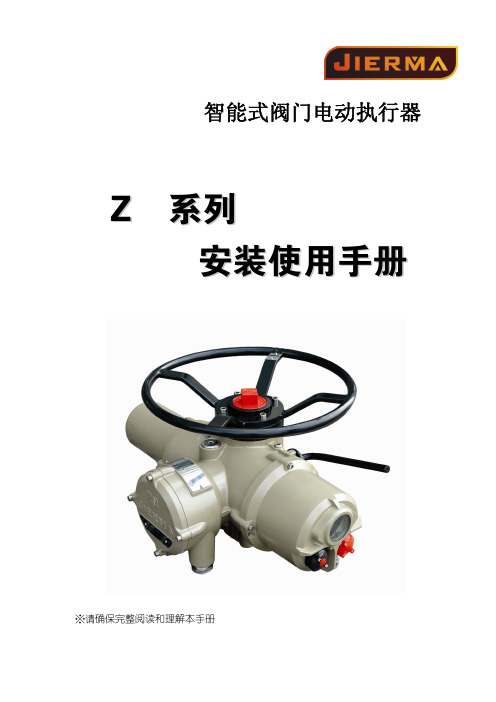
电动执行器样本-吉盛
吉尔马电动执行器说明书
如无意外,Jierma产品的双密封结构能 很好地保护内部的电气元件。
调试ZN系列执行器无需打开任何电气 箱盖。
如果由于用户曾经打开过电气箱盖而 使执行器受到损坏,Jierma公司不承担任何 责任。
每一台Jierma执行器在出厂前都已经 过全面检测,如果安装、调试和密封适当, 则可提供多年的无故障运行。
3.1 手动操作 ................................... - 4 3.2 电动操作 ................................... - 4 3.3 显示 - 就地指示 ..................... - 4 3.4 显示 - 报警指示 ..................... - 5 4 准备驱动轴套 ....................................... - 7 -
任何用于执行器的测试仪器都应有同 等认证。这些执行器的电气安装、维护及使 用应按照危险气体区域认证的相关实施法 规来进行。
如果执行器符合特殊的危险气体区域 认证,则无需对其进行检查和维修。无论在 任何情况下,都不应对执行器进行任何改 造,因为这将使已经获得的认证失效。
在危险区域内,禁止用导电、导热体接 触执行器,除非进行经特殊允许的工作,否 则应切断电源,将执行器卸下并移到非危险 区域进行维修或保养。
10 维护、监视及故障排除....................- 46 10.1 帮助屏幕................................- 47 10.2 IrDA 诊断和组态...................- 51 -
Thomson Max Jac电动直线执行器安装手册说明书
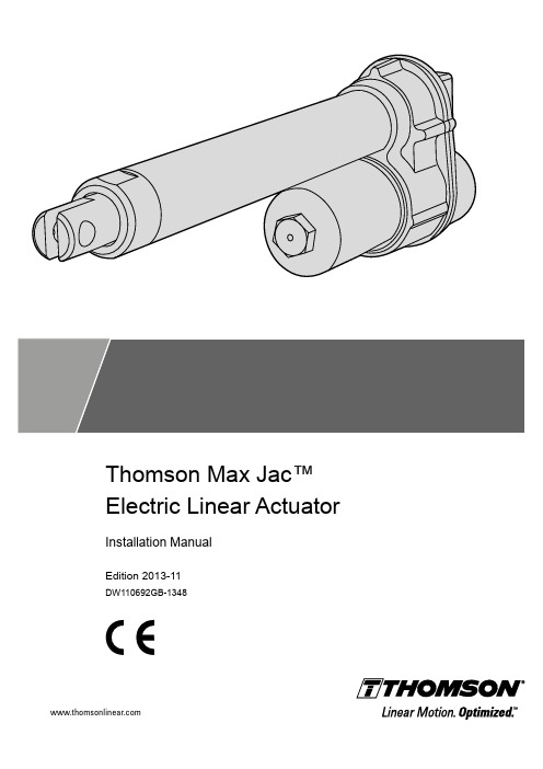
Thomson Max Jac™ Electric Linear Actuator Installation ManualEdition 2013-11DW110692GB-1348ThomsonVersion HistoryEdition Reason for revision2013-11First editionWarrantyThe Thomson Max Jack™ is warranted to be free from defects in materials and workmanship for a period of twelve (12) months from date of delivery. The application of this product is the responsibilityof the buyer and Thomson makes no representation or warranty as to the suitability of the product for any particular use or purpose. For a copy of the entire warranty for this product that is contained in our standard terms and conditions of sale, please go to /website/com/eng/support/terms_and_conditions.php.DisclaimerTechnical changes to improve the performance of the equipment may be made without prior notice! All rights reserved. No part of this work may be reproduced in any form (by printing, photocopying, microfilm or any other method) or processed, copied or distributed by electronic means without the written permission of Thomson.ContentsThomson Contents1. General (4)1.1 About this manual (4)1.2 Target group (4)1.3 Symbols used (4)1.4 Transport and storage (4)1.5 Packaging (4)1.6 Disposal (4)1.7 Support (4)2. Safety (5)2.1 Safety notes (5)3. Standards (5)3.1 EC Declaration of conformity (5)4. Installation (6)4.1 Name plate (6)4.2 Terminology (6)4.3 Operation environment (6)4.4 Mechanical installation (7)4.5 Electrical installation (8)5. Technical specifications (10)5.1 Technical data (10)5.2 Duty cycle vs. load chart (11)5.3 Type designation key (11)Thomson General 1. General1.1 About this manualThis manual decribes how to install the Thomson Max Jac™ electric linear actuator both mechanically and electrically. It also contains, among other things:• technical data• dimensional drawings• type designation key.It is important to carefully read this manual before installing the actuator and to have the correct qualifications needed to perform the installation.1.2 Target groupThis manual addresses qualified mechanical and electrical personnel.1.3 Symbols used1.4 Transport and storageThe actuator may only be transported and stored in the original packaging supplied by Thomson. The temperature during transportation and storage must be between -40 to +85 °C(-40 to +185 °F). Avoid shocks to the package. If the package is damaged, check the actuator for visible damage and notify the carrier, and if appropiate also Thomson.1.5 PackagingThe packaging consists of a cardboard box. The box contains the actuator and this manual.1.6 DisposalWhere required by law, used packaging and actuators are taken back by Thomson for professional disposal if the transportation cost is taken over by the sender. Please contact Thomson for information on where to ship it.1.7 SupportIn case you need technical support or any information related to this product, please contact the nearest Thomson Service Center. See the back of this manual. You can also visit for information on this product and how to get in touch with us.Thomson Safety and Standards2. Safety2.1 Safety notes• Only properly qualified personnel are permitted to perform mechanical and electricalinstallation on this product. Properly qualified personnel are familiar with mechanical or electrical installation work and that have the appropiate qualifications for their jobs.• Read this manual and any other available documentation before working on the equipment.that the actuator is or shall be a part of.• Keep strictly to the data in this manual and on the name plate on the actuator and neverexceeed the performance limits stated herein.• Never work on the actuator or its installation with the power on.• Never unplug any cables or connectors during operation or with power on.• Immediately stop using the actuator if it seems faulty or broken in any way and notify anappropiate person so that corrective actions can be taken.• Never try to open the actuator as that will compromise the sealing and the function of theactuator. There are no serviceable components inside.• Grease may be present on the extension tube. Contact is non-hazardous. Film should not be removed.3. Standards3.1 EC Declaration of conformityWe, Tollo Linear ABdeclare that this products corresponds with the directive 2006/42/EC annex 2.1.B, RoHS II directive 2011/65/EU, WEEE directive 2002/96/EC, low voltage directive 2006/95/EC (EN60204-1:2006+A1:2009) and also with the directive of electromagnetic compatibility 2004/108/EC (EN55014-1:2006+A1:2009, EN61000-6-3:2007, EN61000-3-2:2006+A2:2009, 61000-3-3:2008) and that the standard EN ISO 12100:2010, Safety of machinery, have been applied.Thomson Max Jac™ Linear Actuator MX12(24)xxxxxxxProduct DescriptionCan be used when the machine or the system, which it shall be, a part of is in accordance with the demands in the EEC Machinery Directive and/or other relevant regulations.Kristianstad 2013-06-19DateHåkan Persson Business Unit ManagerName Title SignatureThomson4. Installation4.1 Name plateThe name plate can be found on the actuator housing. It will tell you which model of actuator you have and its basic performance data. Please study the name plate to see what type of actuator you have before starting any installation or service on the actuator. If you need any assistance from Thomson, please tell us the manufacturing date and the deisgnation of the actuator(s) in question.4.2 Terminologya. cable outlet c. housing e. cover tube g. front adapterb. rear adapter d. motor f. extension tube4.3 Operation environmentInstallationMin. -40° C (-40° F) Max. +85° C (+185° F) IP66 / IP69KbcdfgeThomson4.4 Mechanical installationAlways install actuator so that the force of the load acts in the center of the extension tube and the rear adapter and support the mounting pins at both ends (a). Only mount the actuator to the rear and frontmounting adaptors using solid pins (b). The mounting pins must be parallel to each other both radially and axially and be supported in both ends.Failure modes of the actuator should be considered to ensure it does not create harm.Do not hold the extension tube while the tube is rotating or the unit is energized.InstallationThomsonInstallation4.5 Electrical installation4.5.1 General notes• Make sure the leads/cables leading to the motor can handle the maximum motor current.• We recommend to include an emergency stop to avoid any crushing hazard.• Never work on the actuator or the wiring with the power switched on!4.5.2 Fuse sizeProtect the actuator and the wiring by using a slow blow fuse between the actuator and the power source. See table below for recommended fuse size.4.5.3 Wire cross sectionsT o avoid malfunction due to voltage drop the cross section of the wires between the actuator motor and the power source must be of sufficient size. For longer cables than stated in the table calculations based on the supply voltage, the current draw, the length of the cables and the ambient temperature must be done.4.5.4 Connector wiring configurationsThe actuator either has flying leads or an AMP Superseal Series 1,5 connector. In case of a connector the cable leads are connected to the connector pins as shown in the diagram below.Wire cross sections Length of cable (L)Min. allowed cross section (X)00 - 10 m 1.0 mm 2 (AWG 18)10 - 20 m1.5 mm 2 (AWG 14)Actuator with analog feedback (standard)FunctionLead No.Pin. No.Potentiometer supply voltage 0 VDC 11Potentiometer supply voltage 5 VDC 22Potentiometer output signal 33Motor supply voltage 44Motor supply voltage55Actuator with digital feedback (option E)FunctionLead No.Pin. No.Encoder supply voltage 0 VDC 11Encoder supply voltage 5 VDC 22Encoder channel B output signal 33Encoder channel A output signal 44Motor supply voltage 55Motor supply voltage66* Leads for motor connections.** Leads for signal/logic connections.Recommended fuse size Actuator supply voltage Fuse size 12 VDC 10 A 24 VDC5 AThomson4.5.5 Installation of standard actuator with analog feedback 4.5.6 Installation of actuator with digital feedback (option E)By switching the polarity of the voltage to the motor the extension tube will changedirection. Make sure the switch used canhandle the maximum motor current.Warning! The actuator voltage muststroke overload to avoid causing damage to the actuator.By switching the polarity of the voltage to the motor the extension tube will changedirection. Make sure the switch used can handle the maximum motor current.Warning! The actuator voltage must stroke overload to avoid causing damage to the actuator.Installation M Actuator motorS1 Double pole double throw (DPDT) switch F FuseE Digital feedback deviceM Actuator motorS1 Double pole double throw (DPDT) switch F FuseP Analog feedback device+–+Thomson5. Technical Specifications5.1 Technical data(1) Specifications are subject to change without notice. It is the responsibility of the product user to determine the suitability of this product for a specific application.(2) The static force (i.e. the backdriving force) for a ball screw unit varies and is dependant on the number of cycles it have been running and at wich loads.(3) Strokes possible for ball screw models only.(4) For ball screw actuator with 100 mm stroke, average load of 500 N and changing load direction.ThomsonThomson Max Jac™ Electric Linear Actuator - Installation Manual - 2013-11115.2 Duty cycle vs. load chart5.3Ordering KeyDynamic load [N] (lbs)ED @ 25 °C [%]040802060100600(155.0)700(167.5)800(180.0)100(22.5)200(45.0)300(67.5)400(90.0)500(112.5)DW110692-GB-1348 ENGSpecifications are subject to change without notice. It is the responsibility of the product user to determine the suitability of this product for a specific application. All trademarks property of their respective owners. © Thomson 2013. EUROPEUnited KingdomThomsonPhone: +44 (0) 1271 334 500Fax: +44 (0) 1271 334 501E-mail:**************************GermanyThomsonNürtinger Straße 7072649 WolfschlugenPhone: +49 (0) 7022 504 0Fax: +49 (0) 7022 504 405E-mail:*******************************FranceThomsonPhone: +33 (0) 243 50 03 30Fax: +33 (0) 243 50 03 39E-mail:******************************ItalyThomsonLargo Brughetti20030 Bovisio MasciagoPhone: +39 0362 594260Fax: +39 0362 594263E-mail:*********************SpainThomsonRbla Badal, 29-31 7th, 1st08014 BarcelonaPhone: +34 (0) 9329 80278Fax: + 34 (0) 9329 80278E-mail:***************************SwedenThomsonEstridsväg 1029109 KristianstadPhone: +46 (0) 44 24 67 00Fax: +46 (0) 44 24 40 85E-mail:***********************************SOUTH AMERICAThomsonSao Paulo, SP BrasilPhone: +55 11 3879 6600Fax: +55 11 3879 6656Email:******************************USA, CANADA and MEXICOThomson203A West Rock RoadRadford, VA 24141, USAPhone: 1-540-633-3549Fax: 1-540-633-0294E-mail:*************************Literature: ASIAAsia PacificThomson750, Oasis, Chai Chee Road,#03-20, Technopark @ Chai Chee,Singapore 469000E-mail:****************************ChinaThomsonRm 2205, Scitech Tower22 Jianguomen Wai StreetBeijing 100004Phone: +86 400 6661 802Fax: +86 10 6515 0263E-mail:*****************************IndiaThomson India1001, Sigma BuildingHiranandani Business ParkPowai , Mumbai – 400076Phone. +91 22 422 70 300Fax: +91 22 422 70 338E-mail:*****************************JapanThomsonOsaka 564-0044Phone: +81-6-6386-8001Fax: +81-6-6386-5022KoreaThomsonF12 Ilsong Bldg, 157-37Seoul (135-090)Phone: +82 2 6917 5049Fax: +82 2 6917 5007E-mail:*****************************。
电动执行器阀门的介绍

一.电动系列1 电动执行器注:红色部分为引申的下一层角行程电动执行器(配角行程图片(1),加配套文字;配图片角行程DKJ系列(1))直行程电动执行器(配图片直行程电动执行器(1)配文字)多转式电动执行器(配图片多转式电动执行器(1),配文字)2电子式单座双座调节阀(配电动调节阀图片(2),以及文字)3电动蝶阀电动蝶阀(配图片电动蝶阀(3))电动风阀(配图片电动风阀(3))4电动百叶式矩形风阀(配矩形风阀(4)及文字)二.气动系列1气动执行器(配图片气动执行器(5)(6))2气动阀门气动调节阀(配图片气动调节阀(7))气动球阀(配图片气动球阀(7))三.相关配套仪表球型铰链(配图片(8))操作器(配图(9))伺服放大器文字说明1角行程电动执行器S D系列智能型电动执行机构是本公司引进法国技术生产的具有世界先进水平的产品, 其主要部件均为进口,产品严格执行国家标准。
目前生产的SD系列包括角行程、直行程、多转式三大类包括调节型、远控型、开关型等,SD系列智能电动执行机构功能齐全,质量稳定,安全可靠,精度高、规格多、重量轻、安装调试灵活方便,广泛应用于电力、冶金、石化、建材、供热、轻工、水处理、脱硫等行业,在工业过程控制系统中发挥着重要作用。
SD系列电动执行机构是自动调节系统的终端控制装置,它接收来自DCS系统调节器或计算机的4~20mA(或1~5V)模拟量信号及断续接点控制信号,输出力矩或力,自动地操纵调节机构,完成自动调节任务。
它也可以通过操作器实现“手动—自动”转换,切换到手动时,用操作器可对执行机构进行远方控制。
角行程电动执行机构,可用于控制各类转角90°的阀门如:蝶阀、球阀、百叶阀、风门、旋塞阀、挡板阀等。
直行程电动执行机构是输出直线位移的电动执行机构,可用于控制各种需要直线位移的调节阀,如单、双座调节阀、套筒阀、高温高压给水阀、隔膜阀、减温水等调节阀。
产品的种类及型式1、SD系列电动执行机构输出方式分成三种:A.角行程—输出0~90°角位移的力矩。
电动执行器试验报告
电动执行器试验报告执行单元实验报告实验三执行单元一、观察气动薄膜式单座调压阀结构本次实验的目的是通过对气动薄膜式单座调压阀的拆卸和组装对其内部结构和工作原理进行进一步的了解。
执行器按结构可分为执行机构和调节机构。
执行结构是执行器的推动装置,它根据控制信号的大小,产生相应的推力,推动调节机构动作。
调节机构是执行器的调节部分,在执行机构推力的作用下,调节机构产生一定的位移或转角,直接调节流体的流量。
薄膜式执行机构是一种最常用的气动执行机构,具有结构简单、动作可靠、维修方便和价格便宜等优点。
主要由上膜盖、下膜盖、支架、波纹膜片、推杆、压缩弹簧、弹簧支架、调节件、连接螺母等构成。
当信号压力通入上膜盖和波纹膜片组成的薄膜气室时,在膜片上产生一个向下的推力,使推杆下移并压缩弹簧,直到弹簧的反作用力与信号压力在膜片上产生的推力相平衡时,推杆就稳定在一个对应的位置上,推杆的位移即执行机构的输出,也称为行程。
二、测量电动调阀流量特性曲线表1.数据表格理想特性曲线是一条直线,本装置测量曲线有上下波动,经分析应该是由于电动阀内部有堵塞导致。
篇二:检测技术与仪表实验报告实验四单容水箱液位控制系统设计实验一、实验目的1. 通过实验熟悉单回路反馈控制系统的组成和工作原理。
2. 分析PID调节时的过程图形曲线。
3. 定性地研究PID调节器的参数对系统性能的影响。
4. 熟悉组态软件的简单运用。
二、实验要求1. 利用实验室所提供的实验装置,设计一个单回路液位控制系统。
2. 设计实验线路,画出控制系统示意图和控制系统方框图。
3. 要求水箱液位恒定,液位设定值SP自行给定。
4. 无扰动时,水压基本恒定,由变频器控制水泵实现。
5. 分别用P、PI调节时的过程曲线;6. 调节器的参数对系统性能的影响。
7. 运用组态软件设计水箱液位的监控系统。
三、实验设备1. 被控对象:水槽2. 控制器:百特表3. 仪表:液位变送器4. 执行器:电动调节阀5. 附属设施:变频器,水泵等四、实验原理1. 实验原理图2. 单容水箱结构图水箱的出水量与水压有关,而水压又与水位高度近乎成正比。
电动执行器体系图-最终版
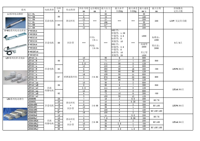
LZ□3L28033LZ□3M640100LZ□3H1224200LZ□5L219633LZ□5M6117100LZ□5H1272200E-MY2B16E-MY2B25E-MY2C16E-MY2C25E-MY2H16E-MY2H25E-MY2HT16E-MY2HT25LEY16□A103862500LEY16□B574174250LEY16□C 2.5141308125LEY25□A12122188500LEY25□B62385016250LEY25□C34525030125LEY32□A161893011500LEY32□B83706022250LEY32□C47076043125LEY16□AA103032500LEY16□AB55864250LEY16□AC 2.5111128125LEY25□AA123573500LEY25□AB672156250LEY25□AC31303012125LESH8RK2041520.5200LESH8RJ2081010.25400LESH16RK4355562200LESH16RJ43103541400LESH25RK67818094150LESH25RJ671610062400LESH8RAK1041120.5200LESH8RAJ1087.510.25400LESH16RAK3053552200LESH16RAJ301020 2.51400LESH25RAK5083664150LESH25RAJ501624 2.5 1.54001000高速型2000其它型1000LC3F/无定位功能直流电机滑动丝杠***2003050***标准品:1000特注品:20003点/5点400E-MY2系列电动无杆缸50中间:±0.1两端:±0.01步进电机同步带******30300±0.02675005240030300******LEY系列出杆式电缸步进电机直流伺服电机研磨滚珠丝杠52LZ系列电动推杆16缸径:轻载型:1.25中载型:2.5标准型:5重载型:1025缸径:轻载型:2.5中载型:5标准型:10重载型:20±0.0550\7550\10050\100\150LECP6/64点LECP6/64点LECA6/64点直流伺服电机滑动丝杠+同步带±0.0550\75LECA6/64点50\10050\100\150 LES系列电动滑台步进电机滑动丝杠+同步带LEFS16A 3010***92500LEFS16B 305***104250LEFS25A 5212***207.5500LEFS25B 526***2015250LEFS32A 6716***4010500LEFS32B 678***4520250LEFS16AA 7010***72500LEFS16AB 705***104250LEFS25AA 11312***11 2.5500LEFS25AB 1136***185250LEFB16T 30***1***11001000LEFB25T 52***5***14001000LEFB32T 67***14***15002000LEFB16AT 86***1***20001000LEFB25AT113***2***20001000LEHZ10K210***14******804LEHZ16K210***14******806LEHZ20K224***40******10010LEHZ25K224***40******10014LEHZ32K233***130******12022LEHZ40K243***210******12030LEHZ10LK28***6******804LEHZ16LK28***8******806LEHZ20LK217***28******10010LEHZ25LK217***28******10014LEHS10K210*** 5.5******704LEHS20K224***22******806LEHS32K233***90******1008LEHS40K243***130******12012LEHS10LK28*** 3.5******704LEHS20LK217***17******806LEHF10K210***7******8016/32(长)LEHF20K224***28******10024/48(长)LEHF32K233***120******10032/64(长)LEHF40K243***180******10040/80(长)步进电机步进电机同步带直流伺服电机LEF系列电动无杆缸直流伺服电机研磨滚珠丝杠400600±0.02800400600LECP6/64点LECA6/64点滑动丝杠+滑动凸轮LECA6/64点48(等效)±0.1±0.02LECP6/64点LEHZ系列2爪式电爪步进电机LECP6/64点步进电机LEHS系列3爪式电爪步进电机滑动丝杠+楔形凸轮LEHF系列2爪式电爪步进电机滑动丝杠+同步带±0.05电机纵置型电机纵置型电机横置型LXPB2BC ***滚珠丝杠2***6530200LXPB2BD ***滚珠丝杠5***6580200LXPB2SA ***滑动丝杠6***65100200LXPB2SB ***滑动丝杠12***33200200LXPB5BC ***滚珠丝杠2***6530200LXPB5BD ***滚珠丝杠5***6580200LXPB5SA ***滑动丝杠6***44100200LXPB5SB***滑动丝杠12***22200200LXSH2BC***滚珠丝杠2***10530150LXSH2BD***滚珠丝杠5***10580150LXSH2SA ***滑动丝杠6***94100150LXSH2SB ***滑动丝杠12*** 4.52200150LXSH5BC ***滚珠丝杠2***10530150LXSH5BD ***滚珠丝杠5***10580150LXSH5SA ***滑动丝杠6***62100150LXSH5SB***滑动丝杠12***31200150LXFH5BC ***滚珠丝杠2***3***30100LXFH5BD ***滚珠丝杠5***3***80100LXFH5SA ***滑动丝杠6***3***100100LXFH5SB***滑动丝杠12***2***200200LJ1S10□1□SC 50滑动丝杠20±0.1***5***3001000LJ1S20□2□SC 100滑动丝杠20±0.1***10***3001200LJ1H10□1□SC 50滑动丝杠20±0.1***10***500600LJ1H10□1□PB 50研磨滚珠丝杠12±0.02***10***600600LJ1H10□1□NB 50滚珠丝杠12±0.05***10***6001200LJ1H20□2□SC 100滑动丝杠20±0.1***15***5001500LJ1S30□3□SC 200滑动丝杠20±0.1***20***300600LJ1H20□2□PA 100研磨滚珠丝杠10±0.02***30***500600LJ1H20□2□NA 100滚珠丝杠10±0.05***30***500600LJ1H30□3□SE 200滑动丝杠40±0.1***30***5001500LJ1H20□2□PC 100研磨滚珠丝杠20±0.02***30***10001000LJ1H20□2□NC 100滚珠丝杠20±0.05***30***10001000LJ1H30□3□PD 200研磨滚珠丝杠25±0.02***60***10001500LJ1H30□3□ND200滚珠丝杠25±0.05***60***10001500LC6D-507AD/无点数限制±0.05±0.03LC1/1008点LC8/117点非标电机型采用电机厂家原配控制器/无点数限制±0.03LC6D-507AD/无点数限制±0.05±0.05±0.03±0.05±0.03LXF系列扁平型电缸LXS系列带高刚度导轨电缸LXP系列带导杆电缸交流伺服电机2相步进电机LC6D-220AD/无点数限制LC6C-220AD/28点LC6D-507AD/无点数限制LC6D-220AD/无点数限制LC6C-220AD/28点±0.03±0.055相步进电机2相步进电机5相步进电机5相步进电机LJ1系列标准型电缸水平安装型LJ1H102□PH 100研磨滚珠丝杠8±0.02***55400500LJ1H102□NH 100滚珠丝杠8±0.05***55400500LJ1H202□PA 100研磨滚珠丝杠10±0.02***88500600LJ1H202□NA 100滚珠丝杠10±0.05***88500600LJ1H102□PB 100研磨滚珠丝杠12±0.02***1010600500LJ1H102□NB 100滚珠丝杠12±0.05***1010600500LJ1H202□PF 100研磨滚珠丝杠5±0.02***1515250600LJ1H202□NF 100滚珠丝杠5±0.05***1515250600LJ1H303□PA 200研磨滚珠丝杠10±0.02***2020500600LJ1H303□NA200滚珠丝杠10±0.05***2020500600LG1□H202□SC 滑动丝杠20±0.1***15***5001200LG1□H202□PA 研磨滚珠丝杠10±0.02***30***500400LG1□H202□NA 滚珠丝杠10±0.05***30***500400LG1□H202□PC 研磨滚珠丝杠20±0.02***30***10001000LG1□H202□NC 滚珠丝杠20±0.05***30***10001000LG1□H212□SC 滑动丝杠20±0.1***15***5001200LG1□H212□PA 研磨滚珠丝杠10±0.02***30***500400LG1□H212□NA 滚珠丝杠10±0.05***30***500400LG1□H212□PC 研磨滚珠丝杠20±0.02***30***10001000LG1□H212□NC滚珠丝杠20±0.05***30***10001000LTF6□E□PF100研磨滚珠丝杠6±0.02***306300600LTF6□E□PH 100研磨滚珠丝杠10±0.02***153500600LTF6□E□NF 100滚珠丝杠6±0.05***306300600LTF6□E□NH 100滚珠丝杠10±0.05***153500600LTF8□F□PH 200研磨滚珠丝杠10±0.02***50105001000LTF8□F□PL 200研磨滚珠丝杠20±0.02***25510001000LTF8□F□NH 200滚珠丝杠10±0.05***50105001000LTF8□F□NL200滚珠丝杠20±0.05***25510001000注意:1、电缸的最大负载(出力)、最大速度、最大行程3个条件通常不能同时满足,选型时请参照样本;2、竖直安装时请选择带锁规格作成:闫立晓内线:16683LG1系列扁平形电缸LC1/1008点LC8/117点非标电机型采用电机厂家原配控制器/无点数限制LTF系列导轨一体型电缸交流伺服电机交流伺服电机100LC1/1008点非标电机型采用电机厂家原配控制器/无点数限制LC1/1008点非标电机型采用电机厂家原配控制器/无点数限制LJ1系列标准型电缸竖直安装型交流伺服电机。
电动执行器说明书LEKF Series

Doc.No. LEKF-OMZ0037-B Electric Actuator / Slider type《High performance Battery-less absolute encoder type》LEKF SeriesApplicable models :LEKFS*G#This manual describes the dedicated terms for “LEKF*G”.Refer to manual of LEKF series about other details.#Refer to the manual relevant to the controller being used for full operating instructions.Safety Instructions (2)1.Specification (4)2. How to order (5)3. Specific product precautions (6)LEKFS Series / Electric ActuatorSafety InstructionsThese safety instructions are intended to prevent hazardous situations and/or equipment damage.These instructions indicate the level of potential hazard with the labels of “Caution,” “Warning” or “Danger.” They are all important notes for safety and must be followed in addition to International Standards (ISO/IEC)*1) , and other safety regulations.*1) ISO 4414: Pneumatic fluid power -- General rules relating to systems. ISO 4413: Hydraulic fluid power -- General rules relating to systems.IEC 60204-1: Safety of machinery -- Electrical equipment of machines .(Part 1: General requirements)ISO 10218: Manipulating industrial robots -Safety. etc.Caution Caution indicates a hazard with a low level of risk which, if not avoided, could resultin minor or moderate injury.Warning Warning indicates a hazard with a medium level of risk which, if not avoided, couldresult in death or serious injury.DangerDanger indicates a hazard with a high level of risk which, if not avoided, will resultin death or serious injury.Warning1. The compatibility of the product is the responsibility of the person who designs the equipment ordecides its specifications.Since the product specified here is used under various operating conditions, its compatibility with specific equipment must be decided by the person who designs the equipment or decides its specifications based on necessary analysis and test results.The expected performance and safety assurance of the equipment will be the responsibility of the person who has determined its compatibility with the product.This person should also continuously review all specifications of the product referring to its latest catalog information, with a view to giving due consideration to any possibility of equipment failure when configuring the equipment.2. Only personnel with appropriate training should operate machinery and equipment.The product specified here may become unsafe if handled incorrectly.The assembly, operation and maintenance of machines or equipment including our products must be performed by an operator who is appropriately trained and experienced.3. Do not service or attempt to remove product and machinery/equipment until safety is confirmed.1.The inspection and maintenance of machinery/equipment should only be performed after measures to prevent falling or runaway of the driven objects have been confirmed.2.When the product is to be removed, confirm that the safety measures as mentioned above are implemented and the power from any appropriate source is cut, and read and understand the specific product precautions of all relevant products carefully.3. Before machinery/equipment is restarted, take measures to prevent unexpected operation and malfunction.4. Contact SMC beforehand and take special consideration of safety measures if the product is to be used in any of the following conditions.1. Conditions and environments outside of the given specifications, or use outdoors or in a place exposed to direct sunlight.2. Installation on equipment in conjunction with atomic energy, railways, air navigation, space, shipping, vehicles, military, medical treatment, combustion and recreation, or equipment in contact with food and beverages, emergency stop circuits, clutch and brake circuits in press applications, safety equipment or other applications unsuitable for the standard specifications described in the product catalog.3. An application which could have negative effects on people, property, or animals requiring special safety analysis.e in an interlock circuit, which requires the provision of double interlock for possible failure by using a mechanical protective function, and periodical checks to confirm proper operation.LEKFS Series / Electric ActuatorSafety InstructionsCautionThe product is provided for use in manufacturing industries.The product herein described is basically provided for peaceful use in manufacturing industries.If considering using the product in other industries, consult SMC beforehand and exchange specifications or a contract if necessary.If anything is unclear, contact your nearest sales branch.Limited warranty and Disclaimer/Compliance RequirementsThe product used is subject to the following “Limited warranty and Disclaimer” and “Compliance Requirements”.Read and accept them before using the product.Limited warranty and Disclaimer1.The warranty period of the product is 1 year in service or 1.5 years after the product isdelivered,whichever is first.*2)Also, the product may have specified durability, running distance or replacement parts. Please consult your nearest sales branch.2. For any failure or damage reported within the warranty period which is clearly our responsibility,a replacement product or necessary parts will be provided.This limited warranty applies only to our product independently, and not to any other damage incurred due to the failure of the product.3. Prior to using SMC products, please read and understand the warranty terms and disclaimersnoted in the specified catalog for the particular products.*2) Vacuum pads are excluded from this 1 year warranty.A vacuum pad is a consumable part, so it is warranted for a year after it is delivered.Also, even within the warranty period, the wear of a product due to the use of the vacuumpad or failure due to the deterioration of rubber material are not covered by the limitedwarranty.Compliance Requirements1. The use of SMC products with production equipment for the manufacture of weapons of massdestruction(WMD) or any other weapon is strictly prohibited.2. The exports of SMC products or technology from one country to another are governed by therelevant security laws and regulation of the countries involved in the transaction. Prior to the shipment of a SMC product to another country, assure that all local rules governing that export are known and f ollowed.CautionSMC products are not intended for use as instruments for legal metrology.Measurement instruments that SMC manufactures or sells have not been qualified by type approval tests relevant to the metrology (measurement) laws of each country.Therefore, SMC products cannot be used for business or certification ordained by the metrology (measurement) laws of each country.LEKFS*GHorizontal 152840405068266075Vertical 37.51541018 4.5 4.525Up to 40020 to 150012 to 750 6 to 50024 to 130016 to 10008 to 50030 to 120020 to 100010 to 500401 to 50020 to 110012 to 750 6 to 40024 to 130016 to 9508 to 50030 to 120020 to 100010 to 500501 to 60020 to 90020 to 54020 to 27024 to 120016 to 8008 to 40030 to 120020 to 100010 to 500601 to 70020 to 63020 to 42020 to 23024 to 93016 to 6208 to 31030 to 120020 to 90010 to 440701 to 80020 to 55020 to 33020 to 18024 to 75016 to 5008 to 25030 to 114020 to 76010 to 350801 to 900---24 to 61016 to 4108 to 20030 to 93020 to 62010 to 280901 to 1000---24 to 50016 to 3408 to 17030 to 78020 to 52010 to 2501001 to 1100------30 to 66020 to 44010 to 2201101 to 1200------30 to 57020 to 38010 to 190201262416830201047781577210821675113245Note1) Please consult with SMC for non-standard strokes as they are produced as special orders.Note2) The maximum work load at 3000mm/s2.Speed changes according to the work load. Check “Speed–Work Load Graph (Guide)” on pages # and #. Furthermore, if the cable length exceeds 5 m, then it will decrease by up to 10% for each 5 m.Note3) A reference value for correcting an error in reciprocal operationNote4) Impact resistance: No malfunction occurred when the actuator was tested with a drop tester in both an axial direction and a perpendicular direction to thelead screw. (The test was performed with the actuator in the initial state.)Vibration resistance: No malfunction occurred in a test ranging between 45 to 2000 Hz. The test was performed in both an axial direction and a perpendicular direction to the lead screw. (The test was performed with the actuator in the initial state.)Note5) The power is for when the actuator is operating. This value can be used for the selection Note6) With lock onlyNote7) For an actuator with lock, add the power consumption for the lock.A c t u a t o r s p e c i f i c a t i o nSpeed [mm/s]Max acceleration/deceleration [mm/s 2]5000LEKFS40±0.01 (Lead H :±0.02)Operating temperature [℃] 5 to 40Actuation type Ball screw(LEKFS □), Ball screw + Belt(LEKFS □R L )Impact/Vibration resistance [m/s 2] Note4)50/20Guide typeLinear guide 150 to 1200Work load [kg] Note2)E l e c t r i c s p e c i f i c a t i o nModelLEKFS25LEKFS32L o c k u n i t s p e c i f i c a t i o nTypeNote6)Non-magnetizing lockHolding force [N]Power consumption [W] Note7)555Power supply voltage [V]24VDC±10%Operating humidity [%RH]90 or less(No condensation)EncoderPower [W] Note5)7)Max. 126Max. 222Max. 222Battery-less AbsolutePower supply voltage [V]24VDC±10%Motor size□42□56.4Motor type Battery-less Absolute (Step Motor 24VDC )Positioning repeatability [mm]Lead [mm]Lost motion[mm] Note3)0.05Stroke [mm]50 to 80050 to 1000Stroke range10000Weight SeriesStroke[mm]50100150200250300350400450500600700800Product weight[kg]1.71.82.02.12.32.42.5 2.62.82.93.23.53.8Additional weight with lock[kg]SeriesStroke[mm]501001502002503003504004505006007008009001000Product weight[kg]3.63.84.04.24.54.74.95.1 5.35.55.96.36.77.17.5Additional weight with lock[kg]SeriesStroke[mm]150200250300350400450500600700800900100011001200Product weight[kg]5.55.86.16.46.77.07.37.68.28.89.410.010.611.211.8Additional weight with lock[kg]LEKFS250.26LEKFS320.53LEKFS400.53Nil In-lineR Right side parallelLLeft side parallel②Motor mounting positionNil Without option B With lock⑥Motor optionRobotic cable [m]Nil None R88R1 1.5RA 10R33RB 15R55RC20⑧A ctuator cable type/length 5050to to 12001200⑤Stroke*For details, refer to the applicablestroke table below.Nil With N Without (Roller specification)⑦Grease application (Seal band part)5010015020025030035040045050060070080090010001100120025●●●●●●●●●●●●●----32●●●●●●●●●●●●●●●--40--●●●●●●●●●●●●●●●Size A pplicable Stroke Table Stroke GHigh performance Battery-less Absolute (Step Motor 24VDC )③Motor type ①Size253240Symbol LEKFS25LEKFS32LEKFS40H 202430A 121620B 6810④Lead[mm]L E K F S 32G A -300-R1CDH7T①②③④⑤⑥⑦⑧⑨⑨Controller Nil Without controllerC □H □□With controller/Input/Output)Symbol Type Applicable interface 5Parallel input (NPN)Nil Without accessory -6Parallel input (PNP)1I/O cable (1.5m )E EtherCAT®3I/O cable (3m )9EtherNet/IP™5I/O cable (5m )P PROFINET7Screw mountingSingle axis8*1DIN rail /High performance*1 The DIN rail is not included. Order it separately.*2 Select "Nil" for anything other than Parallel input. Select "Nil","1", "3", or "5" for Parallel input.Controller mounting Parallel input (NPN)Parallel input (PNP)(Communication protocal InterfaceCommunication plug connector I/O cable*2C 5H 7TCautionActuator and controller are sold as a set.When purchasing without controller,make sure that the combination of actuator and controller is correct.<Be sure to check the following before use.>①”Actuator” matches “Actuator part number described in controller.”(1)LEKFS32GA-3003.Specific product precautionsAbout precautions for installation of actuator, refer to 【Specific precautions for Battery-less absolute encoder】that is described in the manual of used controller.Revision historyNo.LEKF-OMZ0037Mar. / 2022 1st printingNo.LEKF-OMZ0037-AMar. / 2022 RevisionNo.LEKF-OMZ0037-BFeb. / 2023 Revision4-14-1, Sotokanda, Chiyoda-ku, Tokyo 101-0021 JAPANTel: + 81 3 5207 8249 Fax: +81 3 5298 5362URL http: / /Note: Specifications are subject to change without prior notice and any obligation on the part of the manufacturer.© 2019 SMC Corporation All Rights Reservedd。
南京吉申特电动执行器说明书
南京吉申特电动执行器说明书一、产品概述南京吉申特电动执行器是一种用于控制阀门、闸板、球阀等工业设备的电动执行器。
它采用先进的电动机和传动装置,实现对阀门等设备的开关、调节和控制,具有方便、快捷、精确的特点。
二、产品特点1. 高精度控制:南京吉申特电动执行器采用先进的电动机和传动装置,能够实现精确的阀门开关和调节,保证工业设备的正常运行。
2. 快速响应:该电动执行器具有快速响应的特点,能够在短时间内完成对阀门等设备的开关和控制,提高工作效率。
3. 高可靠性:南京吉申特电动执行器采用优质的材料和先进的制造工艺,具有高可靠性和稳定性,能够在恶劣的工作环境下正常运行。
4. 节能环保:该电动执行器采用电动驱动方式,相比传统的液压或气动执行器,具有节能环保的优势,减少了能源的消耗。
5. 远程控制:南京吉申特电动执行器支持远程控制,可以通过网络或无线通信方式实现对设备的远程监控和控制,提高工作效率和便捷性。
三、产品应用南京吉申特电动执行器广泛应用于石油化工、电力、冶金、水处理、制药等领域的工业设备控制系统中。
主要应用场景包括:1. 石油化工:用于管道的开关和调节,如石油、天然气输送管道的控制。
2. 电力:用于电站的阀门控制,如锅炉、汽轮机等设备的调节和控制。
3. 冶金:用于冶金行业的阀门控制,如高炉、转炉等设备的操作和调节。
4. 水处理:用于水处理系统中的阀门控制,如给排水系统、污水处理系统等。
5. 制药:用于制药行业的阀门控制,如药品生产设备的操作和调节。
四、产品结构和工作原理南京吉申特电动执行器主要由电动机、传动装置、控制系统和外壳等部分组成。
其工作原理如下:1. 电动机:电动执行器采用电动机作为驱动源,通过电机的旋转运动带动传动装置实现对阀门等设备的控制。
2. 传动装置:传动装置将电动机的旋转运动转化为直线或旋转运动,将其传递给阀门等设备,实现对其的开关和调节。
3. 控制系统:控制系统是电动执行器的核心部分,通过控制系统可以实现对电动执行器的远程控制和监控,包括开关控制、速度控制、位置反馈等功能。
电动执行器SKD62
电动执行器SKD62简介电动执行器是一种将电能转换为机械能的装置,常用于工业自动化控制系统中。
SKD62型电动执行器是一种专用于工业控制系统的执行器,具有良好的动力性能和控制特性,适用于电动阀门、调节阀等控制装置的驱动。
技术参数•电源电压:AC 220V 50Hz•额定功率:10W•最大输出扭矩:50Nm•旋转角度:0~90度•控制信号:4-20mA、0-10V、伺服信号•工作温度:-20℃~+50℃特点和优势1.高效能:SKD62型电动执行器具有高效能的特点,采用低噪音、高转矩、平衡式驱动设计,保证了机械系统的精简和高效运转。
2.高精度:执行器内置优化算法,能够实现精确的位置控制和速度控制,结合控制系统的迭代控制器,确保位置、速度控制的精度和稳定性。
3.低噪音:SKD62型电动执行器采用精密设计的声学喇叭,使机器的噪音降至最低,可以满足需要安静、高效、低噪音的场合,并保证操作人员的安全。
4.长寿命:SKD62型电动执行器采用优质材料和合理的结构设计,达到了长寿命的要求,可靠性高。
5.海量算法能力:SKD62型电动执行器内置多种控制算法,如PID控制、分段控制、预备计划的控制等,可以满足多种控制场景的需要。
应用场景SKD62型电动执行器广泛应用于石化、冶金、电力等工业自动化领域中,主要用于电动阀门、调节阀等控制装置的驱动。
它在液压传动、气动传动等领域上的代替性越来越强,因为它具备以下优势:1.控制精度高。
2.灵活性好,支持多种控制信号。
3.能够实现高效、低噪音、低能耗。
4.具有良好的抗震性能和耐磨损性,安全可靠。
安装和维护安装时需遵循以下步骤:1.将电动执行器按照说明书取出,注意避免正反装反,接线不要接错,以避免发生短路等安全隐患。
2.请先检查执行器的各部分组件是否完好无损,特别是电源线、接线器、电机等。
3.首先将执行器的电源线接好,并根据现场的控制系统要求连接对应的输入输出信号线。
4.正确设置执行器的安装位置和角度,并通过执行器上的控制开关进行测试。
电动执行器全系列说明_smc电缸培训资料
最大负载[kg]
水平 垂直
30
5
55
10
45
10
85
20
最大速 度
[mm/s]
最大加速度 [mm/s2]
重复定 位精度 [mm]
1200
600 3000~20,000 ±0.02
1200
600
LEJB40 ~2000 20 同步带
LEJB63 ~3000 30
2000
-
3000~20,000 ±0.04
行业/设备 CP/汽车尾灯螺钉热压机 应用产品 LEF系列无杆式电缸
序号
型号
1 LEFS25B-500-R16N1
2 LEFS16AA-400-R16N1
数量 1 1
应用说明:两条LEF配合,找到螺钉上料位置,然后加热,再放至螺钉安装位 置进行热压工作,总计4个螺钉8个工位。
行业/设备 电子/标记印刷机 应用产品 LEFS系列无杆式电缸
驱动方式 电机规格 缸径 行程[mm]
同步带
步进电机 (DC 24V)
LEFB16 LEFB25 LEFB32
300~1000 300~2000
直流伺服 LEFB16A 300~1000
(DC 24V) LEFB25A 300~2000
交流伺服 (100W/ 200W/ 400W)
LEFB25S 300~2000 LEFB32S 300~2500 LEFB40S 300~3000
2 LEFS16AA-200-R36N3
数量 1 1
应用说明:LEFS构成的X-Y轴系统用于将电池液加注头精确定位在电池筒上 方,电池筒为多行多列放置。
2.高刚性滑台式 LEJ
对应交流伺服电机
电动执行器.docx
韩国ITQ电动执行器一、介绍1、I-TORK公司设计,生产高性能的电动阀门执行机构,并且提供与阀门自动控制相关的服务,提供最合理的解决方案。
2、ITQ系列电动执行机构是我们综合多年在自动化领域工作经验而研发出来的重要的成果,它具有紧凑的外形,坚固的结构,可靠的性能,并且能应用于各种复杂控制系统。
3、I-TORK公司会为您提供优质的电动执行机构和附件,以及高品质的服二、特征1、ITQ系列电动执行机构具有紧凑的外形和坚固的结构,重量轻,可以输出较大的力矩(最大输出力矩可以达到3000Nm);2、输出力矩变化的范围很大(从最小100Nm到最大3000Nm);3、ITQ系列电动执行机构具有经氧化处理的铝合金外壳和聚酯粉末外涂层,有很强的防腐能力,能适应各种严酷的工况;4、外壳使用O型圈密封,具有很好的防水性能,防护等级可以达到IP67,并且可选IP68;5、安装底座符合ISO5211标准;6、具有可拆卸的传动轴套,极易加工和装配;7、双蜗轮蜗杆机构具有自锁功能,防止反转;8、手动操作可通过扳动离合器手柄实现,通电后离合器可自动复位;9、可靠的力矩系统可以提供过载保护;10、指示器部分窗口较大,从远处就可以看出阀门的位置指示;11、具有各种各样的就地位置控制选项,极其方便现场操作;12、具有数字控制元件。
三、结构1、外壳铝合金外壳经过氧化处理,聚酯粉末外涂层,可以适应各种严酷的工况;2、传动机构具有精确的双蜗轮蜗杆机构,低噪声,高输出力矩;3、自锁功能双蜗轮蜗杆机构具有自锁功能,防止反转;4、密封性能O型圈密封,防护等级达到IP67,双O型圈密封等级可达到IP68(可选);5、手轮手轮的大小取决于根据执行器力矩的大小,带把手,便于操作;6、电机特殊设计的感应电机,内置热保护开关,防止电机过热;绝缘等级为F;7、外部机械限位阻止限位开关失效时超行程;8、传动轴套传动轴套可拆卸,安装底盘符合ISO5211标准;10、上下壳体结合部上下壳体结合面有斜度,拆装非常方便;有标准型和防爆型两种;11、指示器具有精确连续的机械位置指示盘;12、力矩开关当阀门力矩过大时提供过载保护,开、关力矩开关各有一个;13、限位开关可精确定位阀门位置,辅助限位开关可提供干触点信号(最多4个);14、接线端子弹簧压紧的接线端子使接线牢固,可在振动环境中使用;15、干燥器干燥器可以防止水气冷凝;16、离合机构合上离合器手柄可进行手动操作,通电时自动复位;四、标准配置(ITQ0100-3000)外壳气候防护型IP67,NEMA4 and 6,O型圈密封输入电源110/220VAC(单相) 50/60Hz,380/440VAC(三相)50/60/Hz±10%控制电源110/220VAC(三相)/50/60Hz±10%电机占空比(关开式)S2:10min ~30min电机占空比(调节式)S4:30~50%, 300~1200start/hour 电机全封闭鼠笼式感应电机限位开关开/关各2个(SPDT 250VAC/10A )力矩开关开/关各1个(SPDT 250VAC/10A 除ITQ0100) 热保护内置热保护开关,开150℃±5℃,关97℃±15℃行程90°±5°(0°~100°)位置指示器连续的指示器,带指示盘手轮合上离合器手柄即可进行手动操作,通电后自动复位自锁双蜗轮蜗竿机构机械限位开/关各1个,外部可调干燥器5W(110/220VAC),防止水气冷凝电气接口2 × PF 3/4'' TAP润滑EP型润滑脂接线端子有弹簧压紧环境温度-20℃~70℃环境湿度最大90%RH(不凝结)抗振性能XYZ10G.0.2~34Hz,30minutes外涂层干粉(聚酯)五、技术参数型号ITQ0100 ITQ0160 ITQ0240 ITQ0350 ITQ0500 ITQ0800 ITQ1100 ITQ1500 ITQ2000 ITQ3000 额定力矩(Nm)100 160 240 350 500 800 1100 1500 2000 3000电机沾空比(关开式)(%) 40 30 30 30 30 30 30 30 30 30动作时间(S)50HZ 21 26 26 31 31 39 39 93 117 11760HZ 18 22 22 26 26 32 32 78 97 97最大轴径(mm)22 25 25 40 40 48 48 75 75 75额定电流(A)1相/110V/50Hz 0.98 1.60 1.62 1.72 3.60 3.90 3.90 3.60 3.80 3.801相/110V/60Hz 1.10 1.70 1.72 1.80 3.90 4.20 4.30 3.90 4.20 4.201相/220V/50Hz 0.52 0.85 0.87 0.92 1.50 2.05 2.15 1.50 2.05 2.151相/220V/60Hz 0.58 0.90 0.90 0.95 1.60 2.20 2.30 1.60 2.20 2.303相/380V/50Hz 0.43 0.30 0.32 0.32 0.52 0.82 0.84 0.52 0.82 0.843相/380V/60Hz 0.33 0.30 0.32 0.32 0.56 0.88 0.90 0.56 0.88 0.903相/440V/50Hz 0.59 0.30 0.32 0.32 0.55 0.82 0.84 0.55 0.82 0.843相/440V/60Hz 0.42 0.32 0.35 0.35 0.58 0.88 0.88 0.58 0.88 0.88DC/24V 2.8 4.0 5.0 6.8 - - - - - -电机绝缘等级F F F F F F F F F FISO5211安装法兰F07 F07/F10 F07/F12 F07/F12 F07/F14 F07/F14 F07/F14 F16 F16 F16 重量(KG) 7 15 15 20 20 25 25 65 75 75手轮转数10 12 12 14 14 17 17 65 70 70六、可选件代号说明EX 防爆型(ExdⅡB T4) KTL认证WT 防水型(IP68)ALS 辅助限位开关(最多四个)ATS 辅助力矩开关(最多四个)除ITQ0100外。
- 1、下载文档前请自行甄别文档内容的完整性,平台不提供额外的编辑、内容补充、找答案等附加服务。
- 2、"仅部分预览"的文档,不可在线预览部分如存在完整性等问题,可反馈申请退款(可完整预览的文档不适用该条件!)。
- 3、如文档侵犯您的权益,请联系客服反馈,我们会尽快为您处理(人工客服工作时间:9:00-18:30)。
注 JFL05-220S1、JFL05-24S1:内附 1 只辅助开关,触点容量 3A,AC250V。
三. 电气接线图
JFL05-220
JFL05-24
JFL05-220S1
JFL05-24S1
注:24V 产品应经过安全变压器接入;220V 产品接线时,其端子应满足安全间隙规范。
四. 设置与调整
机械限位调节
五. 外型
1. 安装与调试应由经过培训的专业 人员进行。电气接线应符合相关 规范要求,操作时应切断电源, 确保安全。
2. 产品本身不具备短路保护功能, 请在供电回路中设置必要的保护 装置。
3. 通电前确认电压等级相符。 4. 错误的安装可能损坏产品和危及
安全。 5. 本资料为系列产品的通用说明,
4 VA
110~130s
JSB11K
二位式开关量
/
AC220V
12VA
110~130s
JSB12K
10Nm 二位或三位开关量
/
AC/DC24V
4 VA
100~130s 0.9kg 40dB(A)
IP54
JSB12M
DC2~10V
DC2~10V AC/DC24V
4 VA
110~130s
注 后缀加 K 为配置辅助开关,触点容量 3A,AC250V。 后缀加 P 为内附 1 只 10K 反馈电位器。
具体的接线图和参数详见每个产 品的铭牌。
电话:010-84911377 传真:010-84911378
北京吉盛机电设备有限公司
弹簧复位 5Nm 电动执行器使用说明书
一. 概述
JF 系列智能电子式弹簧复位角行程执行机构,在断电时依靠内部弹簧释放能量,对阀门进行操作,被用于高可靠要求的场合。 本产品外形美观、制作精良、安装方便。旋转角度 0º~90º(最大 95º)并可调,全行程自动过载保护,采用万能联轴器输出。可广 泛应用于暖通空调、消防系统中对要求断电自动复位的风阀进行操作。
手动操作(快速复位时切勿操作)
辅助开关调节
在断电时,按箭头方 向手动操作,到位后 先稳住,再轻拨动锁 定钮锁定。
对于后缀 S1 型 产品,可方便地 调节辅助开关的 动作点。
五. 外型及安装尺寸
六.注意事项
设置运转方向
将产品反过来 安装即可改变 输出轴运转方 向。
1. 安装与调试应由经过培训的专业 人员进行。电气接线应符合相关 规范要求,操作时应切断电源, 确保安全。
二. 主要型号和参数
型号
输出力矩
JFL05-220 JFL05-24
5Nm
控制方式 二位式开关量 二位式开关量
反馈信号 / /
电源电压 AC220V AC/DC24V
运行功耗 8VA 8VA
运行时间 电动 90s 弹簧 15s
重量 1.8kg
噪音 电动 50dB(A) 弹簧 65dB(A)
防护等级 IP54
北京吉盛机电设备有限公司
6Nm/10Nm 电动执行器使用说明书
一. 概述
JS 系列智能电子式角行程执行机构,具有体积小、外形美观、制作精良、安装方便等优点。其旋转角度 0º~90º(最大 95º)任
意可调,全行程自动过载保护,采用万能联轴器输出。可广泛应用于暖通空调系统中对风阀、旋流风口、球形喷口等进行操作。
3、以上型号可改为快速型:运行时间为 50~60s,安装使用方法与完全相同。
三. 电气接线图
JSAX1K
JSAX2K
JSAX1M
JSAX2M
后缀加 K
后缀加 P
注:24V 产品应经过安全变压器接入;220V 产品接线时,其端子应满足安全间隙规范。
四. 设置与调整
机械限位调节
辅助开关调节
对于后缀 K 型产 品,可方便地调节 2 只辅助开关的动作 点。
AC220V AC/DC24V
AC220V AC/DC24V
6VA
80~90s 2.0kg
7VA
130~150s 2.2kg 40dB(A)
IP54
8VA
150~170s 2.2kg
1、以上型号后缀 K(即:JSAX1KK):内附 2 只辅助开关,触点容量 3A,AC250V。 注 2、以上型号后缀 P(即:JSAX1KP):内附 1 只 10K 反馈电位器。
三. 电气接线图
JSB01K JSB11K JSB02K JSB12K
JSB02M JSB12M
后缀加 K
后缀加 P
注:24V 产品应经过安全变压器接入;220V 产品接线时,其端子应满足安全间隙规范。
四. 设置与调整
机械限位调节
辅助开关调节
对于后缀 K 型产 品,可方便地调节 辅助开关的动作 点。
具体的接线图和参数详见每个产 品的铭牌。
电话:010-84911377 传真:010-84911378
北京吉盛机电设备有限公司
16/25/40Nm 电动执行器使用说明书
一. 概述
JSA 系列智能电子式角行程执行机构,具有外形美观、制作精良、安装方便等优点。其旋转角度 0º~90º(最大 95º)任意可调, 全行程自动过载保护,采用万能联轴器输出。可广泛应用于暖通空调系统中对风阀、水阀等进行操作。
二. 主要型号和参数
型号
输出力矩
控制方式
反馈信号 电源电压 运行功耗 运行时间 重量
噪音
防护等级
JSAX1K JSAX2K JSAX1M JSAX2M
X=2 ,16Nm X=3 ,25Nm X=4 ,40Nm
2 位式开关量 2 位/3 位开关量
DC2~10V DC2~10V/4~20mA
/ / DC2~10V DC2~10V
2. 产品本身不具备短路保护功能, 请在供电回路中设置必要的保护 装置。
3. 通电前确认电压等级相符。 4. 错误的安装可能损坏产品和危及
安全。 5. 本资料为系列产品的通用说明,
具体的接线图和参数详见每个产 品的铭牌。
电话:010-84911377 传真:010-84911378
五. 外型及安装尺寸
六.注意事项
设置运转方向
1. 安装与调试应由经过培训的专业 人员进行。电气接线应符合相关 规范要求,操作时应切断电源, 确保安全。
2. 产品本身不具备短路保护功能, 请在供电回路中设置必要的保护 装置。
3. 通电前确认电压等级相符。 4. 错误的安装可能损坏产品和危及
安全。 5. 本资料为系列产品的通用说明,
二. 主要型号和参数
型号
输出力矩
控制方式
反馈信号
电源电压
运行功耗 运行时间 重量
噪音 防护等级
JSB01K
二位式开关量
/
AC220V
12VA
110~130s
JSB02K
6Nm
二位或三位开关量
/
AC/DC24V
4 VA
100~130s 0.9kg 40dB(A)
IP54
JSB02M
DC2~10V
DC2~10V AC/DC24V