BE-1105运动控制器用户手册
Belimo SY5-110 电子阀门操作系统用户指南说明书
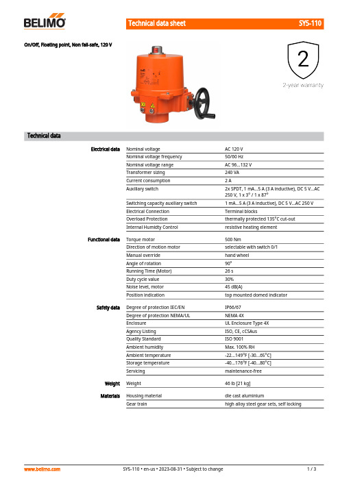
SY5-110On/Off, Floating point, Non fail-safe, 120 VTechnical dataElectrical data Nominal voltage AC 120 VNominal voltage frequency50/60 HzNominal voltage range AC 96...132 VTransformer sizing240 VACurrent consumption2 AAuxiliary switch2x SPDT, 1 mA...5 A (3 A inductive), DC 5 V...AC250 V, 1 x 3° / 1 x 87°Switching capacity auxiliary switch 1 mA...5 A (3 A inductive), DC 5 V...AC 250 VElectrical Connection Terminal blocksOverload Protection thermally protected 135°C cut-outInternal Humidty Control resistive heating elementFunctional data Torque motor500 NmDirection of motion motor selectable with switch 0/1Manual override hand wheelAngle of rotation90°Running Time (Motor)26 sDuty cycle value30%Noise level, motor45 dB(A)Position indication top mounted domed indicatorSafety data Degree of protection IEC/EN IP66/67Degree of protection NEMA/UL NEMA 4XEnclosure UL Enclosure Type 4XAgency Listing ISO, CE, cCSAusQuality Standard ISO 9001Ambient humidity Max. 100% RHAmbient temperature-22...149°F [-30...65°C]Storage temperature-40...176°F [-40...80°C]Servicing maintenance-freeWeight Weight46 lb [21 kg]Materials Housing material die cast aluminiumGear train high alloy steel gear sets, self lockingSY5-110ApplicationProduct featuresSY Series actuators are fractional horsepower devices, and utilize full-wave power supplies. Observe wire sizing and transformer sizing requirements. Proportional models CANNOT be connected to Belimo direct coupled (AF, AM, GM…etc) actuator power supplies or any type of half-wave device. You MUST use a separate, dedicated transformer or power supply to power the SY actuator. Please do not connect other automation equipment to the dedicated SY supply source. You MUST use four wires (plus a ground) to control a proportional control SY actuator (See SY Wiring Section).AccessoriesElectrical accessoriesDescriptionTypeLocal electric disconnect for SY4...12 series actuator, AC 120 V, on/off HOA-120VBattery backup system for SY4...6 series actuator, AC 120 V, on/off EXT-NSV-B03-120Battery backup system for SY4...6 series actuator, AC 120 V, MFT EXT-NSV-B04-120Battery backup system for SY4...5 series actuator, AC 24 V, on/off EXT-NSV-B13-24Battery backup system for SY4...5 series actuator, AC 24 V, MFTEXT-NSV-B14-24Electrical installationINSTALLATION NOTESDo not change sensitivity or dip switch setting with power applied.Power supply Common/Neutral and Control Signal "-"wiring to a common is prohibited.Terminals 4 and 6 need to be wired separately.Isolation relays must be used in parallel connection of multiple actuators using a commoncontrol signal inputs. The relays should be DPDT.Isolation relays are required in parallel applications. The reason parallel applications needisolation relays is that the motor uses two sets of windings, one for each direction. When one is energized to turn the actuator in a specific direction a voltage is generated in the other due to the magnetic field created from the first. It’s called back EMF. This is not an issue with one actuator because the voltage generated in the second winding isn’t connected to anything so there is no flow. On parallel applications without isolation, this EMF voltage energizes the winding it is connected to on the other actuators in the system, the actuators are tying to turn in both directions at once. The EMF voltage is always less than the supply voltage due to the resistance of the windings, so while the actuator still turns in the commanded direction, thedrag from the other reduces the torque output and causes overheating.Warning! Live electrical components!During installation, testing, servicing and troubleshooting of this product, it may be necessary to work with live electrical components. Have a qualified licensed electrician or other individual who has been properly trained in handling live electrical components perform these tasks. Failure to follow all electrical safety precautions when exposed to live electrical components could result in death or serious injury.SY5-110Wiring diagramsAC/DC 110/120 or 220/230VAC 110/120 or 220/230 VElectrical installation。
正运动 VPLC710-I5-ETH5 视觉运动控制一体机 用户手册说明书

运动控制器提供丰富的接口,具有优良的运动控制性能,可以满足各种项目的扩展需求。
本手册介绍了产品的安装、接线、接口定义和操作说明等相关内容。
本手册版权归深圳市正运动技术有限公司所有,在未经本公司书面授权的情况下,任何人不得翻印、翻译和抄袭本手册中的任何内容。
前述行为均将构成对本公司手册版权之侵犯,本司将依法追究其法律责任。
涉及设备软件方面的详细资料以及每个指令的介绍和例程,请参阅Basic 编程手册或PC 函数库编程手册。
本手册中的信息资料仅供参考。
由于改进设计和功能等原因,正运动公司保留对本资料的最终解释权!内容如有更改,恕不另行通知!调试机器要注意安全!请务必在机器中设计有效的安全保护装置,并在软件中加入出错处理程序,否则所造成的损失,本公司没有义务或责任对此负责。
为了保证产品安全、正常、有效的使用,请您务必在安装、使用产品前仔细阅读本产品手册。
产品型号:VPLC710-I5系列机器视觉运动控制一体机用户手册文件名 版本号 版本(更改)说明更新日期 更改人 用户手册V1.0 1. 用户手册发布2023/6/19xcx前言更新记录● 本章对正确使用本产品所需关注的安全注意事项进行说明。
在使用本产品之前,请先阅读使用说明并正确理解安全注意事项的相关信息。
● 本产品应在符合设计规格要求的环境下使用,否则可能导致设备损坏,或者人员受伤,因未遵守相关规定引发的功能异常或部件损坏等不在产品质量保证范围之内。
● 因未遵守本手册的内容、违规操作产品引发的人身安全事故、财产损失等,我司将不承担任何法律责任。
按等级可分为“危险”、“注意”。
如果没有按要求操作,可能会导致中度伤害、轻伤及设备损伤的情况。
请妥善保管本指南以备需要时阅读,并请务必将本手册交给最终用户。
安装危险◆ 控制器拆卸时,系统使用的外部供应电源全部断开后再进行操作,否则可能造成设备误操作或损坏设备;◆ 禁止在以下场合使用:有灰尘、油烟、导电性尘埃、腐蚀性气体、可燃性气体的场所;暴露于高温、结露、风雨的场合;有振动、冲击的场合;电击、火灾、误操作也会导致产品损坏和恶化。
双轴运动控制器操作手册

双轴运动控制器操作手册目录一 与外部驱动器及IO(输入输出)接线图 (3)二 用户管理操作 (4)三 系统参数设置 (5)四 IO(输入输出)设置 (6)五 系统自检操作 (8)六 手动操作 (9)七 编程操作 (11)八 自动执行 (13)九 指令详解 (14)十 电子齿轮计算及公式 (15)十一 编程案例 (17)十二 常见问题及处理 (19)一与外部驱动器及IO(输入输出)接线图1.控制器与步进驱动器或伺服驱动器的连接(红色线为1号线)2.IO(外部开关及继电器)的接线图(红色线为1号线)注:因输入采用低电平有效,若选用光电开关,则需要选择NPN型。
二 用户管理操作注意:所有重要参数只有用户登录以后才可修改保存。
防止他人随意更改参数,影响加工质量。
从主画面进入参数设置,并进入用户管理,进行密码输入。
输入用户密码,按确认键,若输入正确,则提示“用户登陆成功”,否则提示“密码错误,请重新输入”。
用户密码出厂值为“123456”。
用户登录成功后,则可进行加工参数的修改保存。
否则加工参数不可修改保存。
若进入此界面后,提示“用户已登录!”,表示用户登录成功。
然后直接按退出按键,对系统参数及IO 设置进行编辑,编辑完成,再次进入用户管理,并选择用户退出,按确认键,当前参数设置里的内容全部不可更改。
若需要修改,再次进入用户管理进行登录。
注:用户密码可以修改。
但是必须要记忆下新设的密码,否则加工参数将不可修改保存。
三系统参数设置从主界面的参数设置里进入系统参数,通过移动光标,对光标所在位置进行数据修改。
共分4屏,按“上页”“下页”键切换。
控制参数修改完毕可进入速度参数界面进行速度的参数修改,共2屏,修改方式同上。
修改完成后,按参数保存进入参数保存界面,按确认键对当前修改完成的数据进行保存。
若保存成功则提示“参数保存成功”。
注:加工过程中禁止进行参数保存。
按空格键,可将当前参数值清零。
当设定的速度值小于启动速度时,则速度值为启动速度。
SJA1105 Demo 用户手册说明书
类别内容关键词SJA1105Demo 用户手册摘要本文档介绍如何使用SJA1105DemoSJA1105Demo 用户手册车载以太网交换机模块UM010101011.1.00Date:2023/5/11User Manual©2023Guangzhou ZLG Technology Corp.,Ltd.修订历史版本日期原因V1.0.002019/03/06创建文档V1.1.002022/03/01更新文档目录1.功能简介 (1)2.开发环境 (2)2.1软件: (2)2.2工具: (2)3.操作说明 (3)3.1接线 (3)3.1.1调试/下载接口连接 (3)3.1.2车载接线 (3)3.1.3跳帽配置 (4)3.1.4电源连接和上电 (5)3.2编译和下载固件 (5)4.测试 (9)4.1连通测试 (9)4.2速度测试 (10)5.LPC1766MAC通信测试 (12)5.1操作说明 (12)5.1.1电路修改 (12)5.1.2固件下载 (12)5.1.3接线 (12)6.参数说明 (13)7.解决故障 (14)8.参考资料 (15)9.免责声明 (16)1.功能简介SJA1105Demo是基于SJA1105P车载以太网芯片设计的5口交换机其中含一个100Mbps的RJ45接口,4个100Mbps的车载以太网接口。
图1.1SJA1105Demo2.开发环境2.1软件:Keil MDK5.00及以上版本iperf32.2工具:表2.1工具列表工具数量SJA1105Demo1块TJA1100Demo1~4块Jlink或其他下载器1个网线1条双绞线1~4对电脑2~5台路由器1台12V直流电源2~5个3.操作说明3.1接线3.1.1调试/下载接口连接SJA1105Demo的配置程序可以通过板上的调试接口JTAG_LPC(J7)下载,支持SWD 模式和JTAG模式下载。
如图 3.1所示是JTAG接口,表 3.1所示是各个引脚功能的定义。
UB系列控制器操作手册

6
2.1.2 日节能程序时间设定
7
2.2. 设定说明
10
2.2.1 风机状态
10
2.2.2参数设置
10
2.2.3设备运行模式的设定
11
2.2.4 显示内容的设定
12
2.2.5 设备运行状态指示
14
2.3. 报警
15
2.3.1 报警提示
15
2.3.2 传感器异常提示
15
2.3.3 超时报警(仅型号UB2221CH/EN、UB4334SCH/EN适用)
page -10-
⑴ 相对湿度参数设定范围为 20%RH ~ 80%RH ⑵ 在参数设定界面(图2-2-1)按功能键2(切换)选择相对湿度设定。 ⑶ 按上下键改变湿度参数值,步进值为1.0%RH。按住上下键3秒后数值加速改变。当达到湿度范围上限或下限后,相对湿度值不再变化。 ⑷ 确定相对湿度参数后,按图2-2-1中功能键3(确认)或等待15秒后保存并退出参数设定。 2.2.2.4 压力参数设定 (仅型号UB4334SCH/EN适用) ⑴ 压力参数设定范围为 100Pa ~ 2500Pa。 ⑵在参数设定界面(图2-2-1)按功能键2(切换)选择压力设定。 ⑶ 按上下键改变压力参数值,步进值为25Pa。按住上下键3秒后数值加速改变。当达到压力范围上限或下限后,压力参数值不再变化。 ⑷ 确定压力参数值后,按图2-2-1中功能键3(确认)或等待15秒后保存并退出设定状态。 2.2.3设备运行模式的设定
改变输出设备当前值 切换显示温度、相对湿度、压力的设定点参数
选择设置时间、日期、定时
page -4-
状态 时钟设置 日期设置 定时设置下选择日期 定时设置下复制 定时设置下设定
配置状态 恢复出厂设置
PMC100-1运动控制器操作手册第二版(C++版)说明书
PMC100-1运动控制器操作手册第二版(C++版)•2018三英精控(天津)仪器设备有限公司版权申明三英精控(天津)仪器设备有限公司保留所有权利(以下简称三英精控)保留在不事先通知的情况下,修改本手册中的产品和产品规格等文件的权利。
三英精控不承担由于使用本手册或本产品不当,所造成直接的、间接的、附带的或相应产生的损失或责任。
三英精控具有本产品及其软件的专利权、版权和其它知识产权。
未经授权,不得直接或间接地复制、制造、加工、使用本产品及其相关部分。
目录一、概述: (3)二、硬件说明: (4)三、PMC100-1编译器介绍: (7)四、命令介绍: (9)五、附录:样例; (12)一、概述:敬爱的用户:你好!非常感谢您使用PMC100-1步进电机控制器,和国内外同类高档控制器相比,先进的特点如下:1.1、用户编程方便,使用PMC100-1控制器,您不必再为修改程序发愁。
该控制器提供独立的编程环境,不必借助任何工具,您可以随时对程序进行修改或重写。
它的指令设置合理并简单,符合人们的思维习惯,不会在指令的熟悉上浪费您宝贵的时间。
1.2、可控制一轴步进电机。
PMC100-1控制器具有驱动一轴步进电机的能力,并带两个硬件限位点。
1.3、显示方式为真彩TFT液晶屏和触摸屏。
1.4、通用2个输入、2个输出点,实现逻辑控制。
1.5、支持控制器计算机下载。
1.6、支持指令控制。
二、硬件说明:2.1、硬件说明;1、适用于步进电机的各种场合控制应用。
2、提供运算指令,可进行复杂控制。
3、2个通用输入点、2个输出点,实现逻辑控制。
4、2个硬件限位点。
5、8细分步进控制。
2.2、性能指标;1、输出脉冲频率:单轴控制400-30000Hz任意值可设定。
2、1K用户程序空间。
3、当前坐标实时显示。
2.3机箱正视图:1、采用2.8寸TFT液晶屏,触摸屏。
2、实时显示当前位置;初速度;加速度;终速度。
3、提供四个快捷键:前进;后退;运行;回零。
国家实验室智能控制系统多轴运动板手册说明书

Motion ControlNational Instruments548C o n t e n t s a n d O v e r v i e wM o t i o n C o n t r o lContentsMotion Products Selection Guide ..............................550Tutorial . (551)Understanding Motion Basics........................................................551Stepper and Servo Motors..............................................................552Microstepping in Stepper Motor Systems ....................................553Feedback for Closed-Loop Control ................................................554Motion Operation Modes. (555)SoftwareLabVIEW Motion Virtual Instruments............................................556Windows Software for Motion Control..........................................557C Programming for Motion (557)HardwareFlexMotion High-Performance Boards ......................................558Specifications..................................................................................561ValueMotion Boards ....................................................................562Overview..........................................................................................562Stepper Boards................................................................................564Servo Boards ..................................................................................565Specifications..................................................................................566PeripheralsUMI Wiring Interfaces ....................................................................567nuDrive Power Drivers.. (568)Motion ControlOverviewOverviewNational Instruments Phone:(512)794-0100•Fax:(512)683-8411•****************• 549Advanced Motion Performance Using PC-Based StandardsMotion control on the PC is the new standard for intelligent motion integration. The combination of advanced performance, real-time, embedded CPU-based controllers, PCI bus throughput, and Windows graphical programming make PC-based motion the correct choice for powerful, easy-to-use solutions. Motion control on the PC has moved beyond ASCII text programming to interactive graphical interfaces and icon programs on multiprocessor plug-in controller boards, which offload motion tasks from the host PC. These advantages provide seamless integration of motion, vision, data acquisition, and instrument control functions in one system developed using the same software with compatible tools and backed by a uniform worldwide sales and support network. National Instruments motion products are excellent system solutions; they are unsurpassed when used in conjunction with vision and other applications.Motion Products forOEM ApplicationsOEMs need performance, reliability, flexibility, lower cost, and premium support in their motion control products. National Instruments motion control products exceed OEM expectations in all four areas; and as a result, are making equipment manufacturers successful worldwide. Our ValueMotion and FlexMotion products are performance motion controllers with the correct level of compatibility for all OEM applications. Our motion products are manufactured and tested to exceed ISO-9000 quality standards and CE conformance standards.The National Instruments Sales, Support, and Engineering team works closely with OEMs to provide product feature and function enhancement. Our sales people are engineers, trained to make your PC-based measurement and automation application successful.For OEM support well beyondthe industry standard, contact oneof our motion product businessdevelopment managers to discussyour application requirements.What to Look for inMotion Control SystemsA motion control system must make integration of motioncomponents simple while maintaining the performance andflexibility of each component. National Instruments hasdeveloped a premium offering of motion products, and softwaredevelopment tools designed for integration. The connectivitybetween National Instruments motion system componentsfollows industry-standard specifications at each point – controllerto driver, driver to motor, and software to application. Thisconsistency makes your choice of any individual product, or anentire solution, the right choice.To ensure rapid system development, use motion hardwareand LabVIEW graphical programming software for Windowsfrom the same company that designed these tools to worktogether – National Instruments. Spend more time operating yourmotion system and less time figuring out how to configure it. Oursurprisingly simple– yetpowerful – operatorsoftware panels makeit easy to build andrun motionsystems.Motion Control550National InstrumentsPhone:(512)794-0100•Fax:(512)683-8411•****************•Motion ControlTutorialTutorialNational InstrumentsPhone:(512)794-0100•Fax:(512)683-8411•****************•551IntroductionMotion control is a broad term that can be simply defined as the precise control of anything that moves. National Instruments motion control products include PC-based controller boards,wiring, and connectivity devices, power driver units, and software tools and applications. These motion products are optimized for use in test and measurement automation,laboratory automation, industrial control, robotics, material handling, integrated machine vision, CNC machine tool control,and OEM motion applications.National Instruments motion products are designed for powerful yet simple application in both point-to-point and advanced multiaxis coordinated motion systems. The full complement of software tools includes – 32-bit DLL and drivers for C/C++/Visual Basic and LabWindows/CVI in Windows NT/98/95. In addition, the software tools include ready-to-run applications for out-of-the-box motion operation and VIs for graphical object-oriented motion programming with LabVIEW and BridgeVIEW. As a user or integrator of motion control products, it is easy to achieve optimal results and leverage off new standards in motion programming with our PC-based motion control products.PC-Based Architecture for Servo and Stepper ControlServo and stepper motors are widely used for position and velocity control in a variety of electromechanical confie of the PC as an operator interface (HMI), local control host,and remote system controller platform is widely accepted andUsing an intelligent real-time controller board for motion in the PC accomplishes two major objectives in integrating motion,vision, and data acquisition. The first is offloading low-level axis control, closed-loop control, and multiaxis coordination from the host PC; the second is providing a fast, flexible, industry-standard PC-based platform for integrated motion functions.Understanding Motion BasicsA motion control system consists of five major components – the mechanical device being moved, the motor (servo or stepper)with feedback and motion I/O, the motor driver unit, the intelligent controller , and the programming/operator interface software. While solutions exist for a stand-alone distributed motion control and closed architechture motion controllers from other vendors, it is clear that PC-based automation, as well as a focus on PC-based motion solutions and open standards for hardware and software components, is fueling growth in this area.Understanding the requirements of your motion system and the basic technologies for motion are key in selecting products for your application. This tutorial covers motion controller board architecture, servo and stepper motors, motor drivers, feedback for closed-loop control, motion control modes, motion I/O, and industry-standard signals for third-party motion component connectivity. The National Instruments motion products access and control these technologies while emphasizing connectivity between components and graphical tools for development.Motion ControlMotion Control TutorialNational InstrumentsPhone:(512)794-0100•Fax:(512)683-8411•****************•552T u t o r i a lcounter/timer capabilities differently, providing a choice of general-purpose or high-performance solutions. All National Instruments motion controller boards are designed for integrated operation of their dual processor configuration in the LabVIEW and BridgeVIEW graphical programming environments, as well as with LabWindows CVI, C/C++, Visual Basic, and other major development tools.Stepper and Servo MotorsStepper and servo motors are both generic terms covering many technologies. Stepper motors are discrete motion devices that move to positions that relate directly to the number of input control pulses, at a velocity that relates directly to the pulse rate. Servo motors are continuous motion devices that use feedback signals to provide position and velocity control in a closed-loop environment.open-loop servo motor rotates or moves uncontrolled as long as power is applied to it. By implementing a control loop around a servo motor, using a PID controller and feedback from an encoder device mounted on the motor , it is possible to accurately and reliably move to the desired position at well controlled velocities following user-specified motion trajectory paths.All servo motor systems use a motor driver power unit to control the voltage and current that flows through the motor armature and motor windings. The basic principle of motion in servo motors is based on the flow of current through a wire coil,generating a magnetic field that reacts with permanent magnets in the motor to cause attraction and repelling forces that cause movement.M o t i o n C o n t r o lMotion ControlTutorialTutorialNational InstrumentsPhone:(512)794-0100•Fax:(512)683-8411•****************•553DC Brush Servo MotorsThe DC brush servo motor , the simplest servo motor design, is cost effective for its performance and power in general-purpose servo applications. DC brush servo motors are self-commutating motion devices that rotate continuously while current is applied to the motor brush contacts. The current flows through the brushes to the armature and then through the motor coils,creating the magnetic forces that cause motion. Changing the direction of current flow through the motor reverses the direction of rotation. Encoder feedback to the motion board is required to provide accurate control of position and velocity with a DC brush servo motor . Encoders are mounted on the shaft of a motor or on the coupled mechanical unit as a linear or rotary device, directly translating movement into feedback data.Stepper MotorsStepper motors rely on the principle of commutation or alternating magnetic forces, to provide predictable controlled motion. Commutation in motion applications is the controlled sequencing of drive currents and voltages in motor coil windings to provide torque and therefore, movement. In a stepper motor system, individual step signals from a motion control board are converted into an energizing pattern for the motor coils.As the commutation pattern varies, the motor moves from one discrete position to another . When the pattern is held in a single state, the stepper motor holds its position with a known torquefull-step locations of a stepper motor the basic resolution of the motor to as 1.8 degree/step motor revolution per minute (rpm).Microstepping in Stepper Motor SystemsAdvanced stepper motor driver technology provides a capability known as microstepping. Microstepping is based in the stepper motor driver component. It provides for the predetermined subdivision of each full step into microsteps by proportioning the currents in each coil to produce carefully balanced electromagnetic locations between the full steps. To quickly review the technology of microstepping, sine and cosine proportioned values of current are carefully sent to particular motor coils, resulting in the simulation of interim microstep locations. The advantage of microstepping is multiplication of the number of steps per revolution, thereby increasing the resolution of a stepper motor system. Additionally, because more steps are provided, the movement between steps is smaller and the resulting step motion is typically smoother. Microstepping technology is widely accepted and fully implemented in all National Instruments stepper control and driver products.Because stepper motion is controlled by the generation of step pulses from the controller board, it is clear that the stepper motor controller must carefully control the number of pulses (position), the frequency of the pulses (velocity), and the rate of change of frequency (acceleration/deceleration). This process is referred to as trajectory control, where the trajectory is the predictable path of speed changes that the motor undergoes as it moves from its starting position to its desired end position through its profile or as it runs continuously at desired velocities.Motion ControlFigure 3. Stepper Motor Controllers and nuDrives Support MicrosteppingMotion Control TutorialNational InstrumentsPhone:(512)794-0100•Fax:(512)683-8411•****************•554T u t o r i a lFeedback for Closed-Loop Motion ControlMotion systems use feedback signals to provide closed-loop control of position and velocity. Although feedback is optional in stepper motor systems, servo motor systems require feedback for proper control, operation, accurate motor position, and velocity maintenance. The most common feedback used with intelligent motion control boards is quadrature incremental encoder feedback.Feedback devices provide signals that convey position and velocity data to a motion controller . The signals are converted on the motion controller into count values that correspond to position. Position values, measured over fixed periods of time,Quadrature Encoder FeedbackQuadrature incremental encoders are optoelectronic feedback devices that use a patterned optical mask and optointerrupter-LED source/transistor detector pairs to generate two digital output waveforms, where the pulse location of the waveforms are 90 degrees out of phase with each other . This 90 degree phase difference in the waveforms (quadrature) is used by the encoder input circuitry to enhance the resolution of the position count value and to determine the direction of motion. If the A phase signal leads or comes before the B phase signal, then motion direction is considered clockwise or forward. For the opposite phasing, the direction is considered counter-clockwise or reverse.The quadrature encoder input circuits decode the phasing of the signals and count the quadrature pulses to derive position information. The position count value is maintained in a 32-bit register , providing more than 4 billion position locations.The detector circuits for encoder feedback on the motion controller boards incorporate digital signal filtering techniques to avoid deception by noise pulses or erroneous data that does not fit the quadrature model.Analog FeedbackAlthough quadrature encoder feedback is the most common type used, you can use analog feedback to provide the same position and velocity data. If an analog input signal is measured and converted by an ADC on the motion board, the analog value generates a corresponding digital value. This value is then used as position data and the overall range of available positions is determined from the resolution of the ADC. Analog feedback,.acceleration phase. Switching power supplies typically suffer from output shutdown when the motor driver attempts to draw the extra current that it requires during acceleration.National Instruments motion control products provide two different solutions for motor driver configuration. The nuDrive units are fully enclosed motor driver subsystems with a single cable connection from the motion control board. nuDrives include the appropriate motor driver types per axis, for small DC brush type servo or stepper motors, along with bulk DC power supplies specifically designed to provide the voltage and currents demanded by these drivers. Additionally, nuDrive units incorporate all of the necessary low-voltage power supplies,wiring connectivity, signal conditioning, and monitoring that are appropriate for motion system integration with encoders, limit switches, and other motion I/O devices.If nuDrive voltage and current capabilities do not meet the requirements of a specific motor, it is simple to connect to third-party motor drivers using a universal motion interface module (UMI).M o t i o n C o n t r o lMotion ControlTutorialTutorialNational InstrumentsPhone:(512)794-0100•Fax:(512)683-8411•****************•555The UMI accepts the single cable connection from the motion controller board and breaks out the motor , encoder , limit, and motion I/O signals on a per-axis basis into separate pluggable screw terminal connections. The UMI provides all of the onboard signal conditioning and monitoring found in a nuDrive. Because the motion controller board outputs industry-standard signals,through the UMI, this configuration provides for limitless connectivity. You can use any size or type of motor , as long as the associated driver unit is compatible with the standard control and feedback signals.Motion Operation ModesPC-based servo and stepper controller boards offer a wide variety of operation modes. The modes listed provide operational features and functionality at a high level, making it simple to solve motion applications. Access these standard operation modes in a fully integrated motion system with powerful software tools. Easy-to-use Windows software, drivers, and Motion VIs make mode operation, parameter loading, and status display a snap. Motion is controlled in absolute or relative mode, and you can use all position breakpoint, position value capture, and status functions.Point-to-Point Position ModeIn point-to-point mode, each axis is indepen-dently programmed with motion profile parameters. Values for velocity, acceleration,deceleration, S-curve, and target position are loaded prior to a start command.Linear Vector Interpolation ModeIn linear vector interpolation mode, you canassign axes to a vector space; motion control ofthe axes accurately follows the desired vector path, at the programmed vector velocity,acceleration, and deceleration values. Vector spaces can contain one, two, or three axes and you can synchronize multiple vector spaces. You can also sequence and blend motion profiles for smooth transition.Electronic Gearing, Master/Slave ModeIn electronic gearing and master/slave modes,you can configure any axis or axes to run at a gear ratio to any master axis. The master axis could be encoder feedback only, or a motor under closed-loop control. These powerful gearing modes are used for coil winding, flying cutoff, rotating knife, high-speed labeling, and all other geared and slaving applications.Circular, Spherical, and Helical Interpolation ModesIn these modes, the motion parameters describing arcs, vector velocity, accel/decel,radius, start angle, and target angle are loaded before the move is started. For helicalinterpolation, the target height (Z) is also loaded and for spherical interpolation, two start angles and two target angles are specified. Motion will accelerate to the vector velocity while following the path indicated by target angles and height.S-curve on a motion profile is controlled by separate accel-eration and deceleration smoothing (jerk-limit) factors.Velocity Profiling ModeThis mode provides a user-programmed acceleration to a desired target velocity that is accurately maintained until a new target velocity value is loaded. You can change velocity on the fly.Jog Modeparameter is updated on the fly or a stop command is issued.Registration ModeRegistration is used to capture the exact position when the high-speed capture input signal transitions. The high-speed capture eliminateslatency and provides precise motor control athigh velocities. High-speed capture input position values are automatically combined with a registration move; and the new motion can be completed autonomously.Homing ModeHoming is accomplished through the Findindex (marker) pulse of the feedback encoder device, and then moves to the index offset position. Homing mode is used during system setup and initialization.Motion Control。
ABB电动执行器使用说明书

ABB电动执行器使用说明书用于过程自动化的智能型电动执行机构仪器仪表—解决方案1 DS_Ontrac_ZH Rev.B 产品简介历史悠久、拥有执行机构行业世界领先地位的Hartmann&Braun 早在40年前,就开始向中国提供高效的电动执行机构产品,并于八十年代向中国的一家企业转让了RHA 、RS 型生产技术。
1999年Hartmann&Braun 随 Elsag Bailey 过程自动化集团正式并入ABB 集团。
ABB 在淘汰了RHA 、RS 型技术后,于2000年推出了Ontrac 智能电动执行机构。
自诞生之日起,Ontrac 就几乎成为先进性和高可靠性的代名词,至今已在世界各地多个工业领域得到广泛的应用。
Ontrac 是实时多任务嵌入式系统与成熟的ABB 变频驱动技术的完美结合体,由于采用了先进的电子技术,Ontrac 的机械部分已经被简化至极致,这无疑是现代机电产品的一个重要的发展方向。
实践证明,Ontrac 产品可以适应各种复杂的甚至十分恶劣的使用环境。
灵活的功能,稳定的性能以及超长的使用寿命都使选用Ontrac产品成为一种很好的投资方案。
功能时间随着数字信息技术的迅猛发展,控制系统对执行机构的功能要求也越来越高,Ontrac 正是顺应这种趋势,做到了既能与当今最先进的控制系统匹配,又能满足所有传统控制系统的要求。
可以说,选用Ontrac 产品,您在技术上也就争得了先机。
主要特性描述:● 采用先进的ABB 变频驱动技术,实现了柔性启动和停机,彻底摆脱"水锤效应"● 速度和力矩双向独立可调,超大的调整范围大幅降低了用户的选型难度和备品成本●灵活的控制方式选择,即能实现总线控制又能满足开关量模拟量控制,并能够适应各种复杂的有特殊要求的改造项目● 电气部分充分的抗干扰和防冲击设计,使产品运行极为稳定,并有效杜绝了"电网污染"问题● 超高的定位精度,即使在全行程(多回转)1圈的情况下,也能够达到1%的定位精度● 广泛的监视与自诊断功能,帮助用户迅速准确地判断执行机构甚至阀门的运行状态● 完善的安全防护功能,可有效杜绝现场误操作或在系统紧急故障时将危害降低至最小● 简洁高效的人机交互界面和非侵入式设计,使现场安装调试变得异常简单● 可靠的电路设计和简单的机械结构造就了超长的使用寿命技术参数供电电源:三相三线制:220/380/460/55V±10%,50/60Hz±5%单相两线制:110/220V±10%,50/60Hz±5%工作模式:1)开关型MOE产品:连续运行,S2-15min2)调节型MME产品:继续运行,S4-25%,接通次数≤1200/小时电机控制:变频控制内部电源:24V.DC,最大40mA,具短路保护功能外部电源:24V.DC(18~33V),最大500mA输入信号:1)模拟量:4~20mA.DC,输入阻抗250Ω,上升特性2)开关量:脉宽≥50ms,数字0为-3~+5V或开路,数字1为+12~+35V3) Pro?bus-DP输出信号:1)模拟量:4~20mA.DC 负载阻抗≤750Ω,温度影响≤0.1%/10K,上升特性(默认)2)开关量:4副基本无源触点,可增选至7或8副(所有输出触点均可组态),触点容量30V.DC,1A或125V.AC,0.5A,4副基本无源触点也可选250V.AC.8A规格3)Pro?bus-DP或MODBUS行程范围:多转式产品最小圈数为1圈,最大圈数不限设定力矩:40%~100%可调,步距5%设定转速:40%~100%可调,步距5%基本误差:1)多转式电动执行机构(行程≥1圈)≤±0.5% 2)角行程电动执行机构3)直行程电动执行机构(行程≥25mm)≤±0.5%控制死区:0.5%(0.5~10%可调)中途限位:1)开限位设置范围为55%~100%2)关限位设置范围为0%~45%防护等级:IP67(IP68可选)防爆等级:ExdⅡBT4可选环境条件:1)环境温度:开关型MOE为-25℃~+70℃调节型MME为-25℃~+60℃分体式传动部分为-40℃~+85℃2)相对湿度:≤95%3)空气介质:周围空气中无强腐蚀性、易燃、易爆气体除湿加热器:产品内部有专门的发热元器件,一般情况下不需要特殊提供CE电气法规:1) EN 61000-6-4: 2007, EN 61000-6-2: 20052) EN 61000-3-2:2006 +A1: 2009+A2: 2009,EN 61000-3-3: 20083) EN 60204-1:2006+A1:2009安装方向:任意方向抗震能力:5~200Hz内0.75g正弦波或5~150Hz内2g正弦波(分体式:加速度3g:X-28.97Hz,Y-96.68Hz,Z-149.6Hz)注:如果您有其他技术要求,请与我们联系,我们将尽力满足您的需求。
- 1、下载文档前请自行甄别文档内容的完整性,平台不提供额外的编辑、内容补充、找答案等附加服务。
- 2、"仅部分预览"的文档,不可在线预览部分如存在完整性等问题,可反馈申请退款(可完整预览的文档不适用该条件!)。
- 3、如文档侵犯您的权益,请联系客服反馈,我们会尽快为您处理(人工客服工作时间:9:00-18:30)。
第I 页
地址:深圳市宝安区西乡码头路 104 号 电话 0755-26703936
BE-1105 单轴运动控制器用户手册
1 配件清单与安装
1.1 适配电源
双路隔离输入 +24V/1A(控制器工作电压)
1.2 控制器外形尺寸
50mm(长) * 80mm(宽)*32mm(厚)
2.2 功能说明
(停止状态时按下模式开关时 LED 闪烁次数为对应下面模式) (运行状态时按下模式开关再按下正运行或者负运行开关时,对应为速度加和速度减,长按也有 效) 2.2.1 控制应用一:(点动模式)
完全由外部正运行开关和负运行开关控制正反运行,运行开关松开时停止,当碰到极限开关时也停止。 2.2.2 控制应用二:(单次触发模式)
第3 页
地址:深圳市宝安区西乡码头路 104 号 电话 0755-26703936
BE-1105 单轴运动控制器用户手册
上位机控制程序相应按钮可以完成以上应用,并实时控制速度,改变加减速设置等信息,支持总线 集连。建议控制时选择‘单步模式’,这样撞到限位开关时会停下来。
1.3 产品配件清单核对表
打开 BE-1105 运动控制器包装后,你将会发现如下物品:
1、 BE-1105 控制器一台。 2、 专用串口下载线一条(用户选配需单独购买)。
变能官网上下载最新以下资料 :
/list/?8_1.html
a) BE-1105 控制器指令控制调试程序; b) 用户手册(pdf 格式电子文档);
1.1
适配电源............................................................................................................................................. 1
2.3 系统组成
l 高性能、高速度 MCU l 光耦隔离输出运动控制信号最大电流 100mA(信号输出为:+5V-24V 脉冲+方向) l 专用的常闭(或常开)式正负极限限位,光电隔离信号输入口 l 专用的常闭式急停通道 l 支持上位机软件运行指令载入、485 通讯 、串口通讯。
2.4 技术参数
l 最小数据单位:0.001mm l 快速运动限速:3240mm/min(当脉冲当量为 0.001mm 时) l 最高加工速度限速:3240mm/min(当脉冲当量为 0.001mm 时) l 最高脉冲输出频率:60KHz (输出脉冲分辨率小于 1Hz) l 位置控制最大行程 174 米(当脉冲当量为 0.001mm 时) l 控制轴数:1 轴 l 系统主要功能:七种控制模式、速度控制、位置控制、加减速控制 l 支持总线集联:最大连接台数 255 台,总长不超过 1200 米,支持修改控制编号地址
3 BE-1105 控制器接口...........................................................................................5
3.1
信号接入方法 ..................................................................................................................................... 5
第2 页
地址:深圳市宝安区西乡码头路 104 号 电话 0755-26703936
BE-1105 单轴运动控制器用户手册
位置控制时可不需要限位开关,启动停止时有加减速。设备上电后,外部触发启动运行,设备到从 A 点 出发,当设备运行到 B 点正转限位后,设备反向回转运行,当到达 A 点后,电机停止。完成一次 A->B->A 运 动过程。如果在设备运行中触发停止按键电机立即停止运行。 2.2.5 控制应用五:(按设置次数往返运行模式)
1 设备从 A 点到 B 点后停止。再次启动设备从 B 点到 A 点停止。位置控制时可不需要限位开关,启动停 止时有加减速。
设备上电后,外部触发启动运行,设备到从 A 点出发,当设备运行到 B 点正转限位后,设备停止运行, 如果再次启动,设备从 B 点触发到达 A 点后,设备停止。启动 A->B 停止,启动 B->A 停止 的运动过程。如 果在设备运行中触发停止按键电机立即停止运行。
上电(即开机)回零,上电自动运行,位置控制(精确定位),AB 点时间延时 可与以上八种模式组 合使用
通过串口设定行进距离脉冲数(脉冲数=(距离/螺距)*运行 1 圈的脉冲数)后,外部触发启动运行 运行到指定位置停止,再次触发时运行相同距离。‘单步模式时’可以通过正负运行按键实现来回运动。 ‘自动运行模式时’可以实现来回运动,不需要限位开关。 2.2.10 控制应用十:(上位机串口/485 连接控制)
B 点是零点,回零后一直向 A 方向运行。(停留时间可设定) 设备上电后,外部触发回零运行,设备运行到 B 点(即零点)限位后停止,再次触发正运行按键后,向 A 方向运行,当到达 A 限位后停止。如果 A 限位此时松开,设备将继续 A 方向运行,直到再次到达 A 限位后 停止,如此反复。 2.2.7 控制应用七:(前进回零往返模式) B 点是零点,回零后向 A 方向运行再回零。如此反复(停留时间可设定)。 设备上电后,马上进入回零运行,设备运行到 B 点(即零点)限位后停止,再次向 A 方向运行,当到达 A 限位后,再次向到 B 点运行。如此反复具有零点校准作用防止累计误差。 2.2.8 控制应用八:(单方向运行模式) 一直向 A 方向运行。 当触发正运行键后,设备运行到 A 点限位后停止,如果 A 限位此时松开,设备将继续 A 方向运行,直到再 次到达 A 限位后停止,如此反复。 2.2.9 组合控制控制应用九:(上电回零,上电自动运行,位置控制,AB 点时间延时)
2.4
技术参数............................................................................................................................................. 4
2.2.3 控制应用三:(自动往返模式) 设备在 A 点与 B 点之间往返运行。(停留时间可设定) 位置控制时可不需要限位开关,启动停止时有加减速。 设备上电后,外部触发启动运行,设备运行到 A 点正转限位后,自动反转运行到 B 点反转限位后,又 正转运行到 A 点,如此往返运行。直到触发急停按键电机停止运行。 2.2.4 控制应用四:(单次往返模式) 设备从 A 点到 B 点后返回到 A 点停止。(停留时间可设定)
脉冲输出 开关量输入 应用环境
脉冲输出方式:脉冲+方向 脉冲输出 集电极开路输出 OC 模式 OC 模式最高输出频率 60KHz 脉冲输出频率在最高的时候也能做到 0 个脉冲误差 3 路光偶隔离用户按键设置通道,响应时间 0.3ms 1 路光偶隔离急停输入通道,响应时间 0.3ms 2 路限位开关专用光偶隔离开关量输入通道,响应时间 0.3ms 输入电压+6~24V (默认公共端接+5V,高于此电压时串接限流电阻,驱动电流 5mA) 隔离电压 2500V DC
2 概 述................................................................................................................2
2.1
行业应用............................................................................................................................................. 2
第1 页
地址:深圳市宝安区西乡码头路 104 号 电话 0755-26703936
BE-1105 单轴运动控制器用户手册
2概 述
2.1 行业应用
2.1.1 作业生产:包装机、装配机 、搬运机器人、送料机器人、生产线代替人工。 2.1.2 切割焊接:布料剪切、钢板焊接、钢板切割、木板切割、亚克力、玻璃切割、PCB 切割等。 2.1.3 门类控制:小区闸门、高速路匝道、自动闸门、来回伸缩闸门,电梯门等
4.1
程序指令说明 ................................................................................................................................... 10
5 PC 控制程序下载指令操作..............................................................................14
2.3
系统组成............................................................................................................................................. 4
1.2
控制器外形尺寸 ................................................................................................................................. 1
1.3
产品配件清单核对表 .........................................................................................................................1