Dissipative free-surface solver for potential flow around hydrofoil distributed with doublets
膦催化α,β-不饱和化合物的转化及吲哚去芳构环化反应研究

膦催化α,β-不饱和化合物的转化及吲哚去芳构环化反应研究过去的几十年里,叔膦催化已经发展成为有机合成领域的一个研究热点,该类反应能够高效构建多种碳环及杂环化合物,因此,叔膦催化合成反应的发展和应用备受化学家们的广泛关注。
特别是,多样性手性叔膦的开发,高选择性的实现了多类合成反应的不对称催化,为天然产物、药物模块全合成及其它生物活性分子的合成开辟了新途径。
近几年来,本课题组发展了几类新型的双功能手性叔膦催化剂,如叔丁基亚磺酰胺类型手性单膦Xiao-Phos,叔丁基亚磺酰胺类型手性双膦Wei-Phos和3,5-二三氟甲基苯甲酰胺类型手性叔膦Peng-Phos,它们分别在不对称分子内Rauhut-Currier反应、不对称分子间Rauhut-Currier反应和不对称烯丙基化反应中具有优异的表现。
本论文以本组发展的一系列手性叔膦催化剂为基础,进一步探索手性叔膦催化的不对称新反应,主要内容有以下几个方面:1.膦催化不对称[4+2]-环加成反应构建多取代四氢吡啶化合物研究实现了在手性叔膦P2.6或者P2.7催化下,三氟甲基取代的α,β-不饱和亚胺与烯酮的不对称[4+2]-环加成反应,且以高收率(高达97%),高非对映选择性(>20:1 dr)和对映选择性(高达97%ee)构建了一系列含三氟甲基取代的四氢吡啶类化合物。
另外,在叔丁基亚磺酰胺手性叔膦P2.2作用下,查尔酮类型的亚胺同样能与丁烯酮发生环化反应,以优秀的对映选择性(高达92%ee)得到相应的产物。
机理研究证明手性叔膦与烯酮加成得到的两性离子中间体具有双重身份,既是整个反应的底物,又是迈克尔加成反应的催化剂。
2.膦催化α-取代联烯酮和α,β-不饱和酮的不对称[4+2]-环加成反应发展了一类二茂铁衍生的多功能叔膦催化剂P3.5,该催化剂能高效的实现全氟烷基取代α,β-不饱和酮与联烯酮的不对称[4+2]-环加成反应,构建一系列高收率和优异的对映选择性(90-99%ee)的三氟甲基取代二氢吡喃衍生物,并且具有很好的官能团容忍性。
表观遗传学简述ppt课件.pptx

总结
表观遗传学信息提供了何时、何地、以何种方式去 执行DNA遗传信息的指令,它通过有丝分裂和减数 分裂将遗传信息从上一代传递给下一代。
决定表观遗传学过程的主要因素为DNA的甲基化、 组蛋白修饰、染色质重塑和非编码RNA调控,这4个 因素的相互关系以及它们如何共同来调节染色质 结构还有待进一步研究。
甲基转移作用通常发生在 5′-胞嘧啶位置上, 具有调 节基因表达和保护DNA该 位点不受特定限制酶降解 的作用。
2、组蛋白修饰
组蛋白是真核生物染色体的基本结构蛋白,是一类 小分子碱性蛋白质,有5种类型:H1、H2A、H2B、H3、 H4,它们富含带正电荷的碱性氨基酸,能够同DN中带 负电荷的磷酸基团相互作用。
小组成员及分工
谢吕欣:表观遗传学最新研究进展资料查找 陈绪:表观遗传学作用机制资料查找、PPT报告 庞锡泉:表观遗传学前沿方向资料查找 金丽菁:PPT制作、文献资料汇总整理
THANK YOU FOR WATCHING
染色质重塑是指 在能量驱动下核 小体的置换或重 新排列,它改变了 核小体在基因启 动子区的排列,增 加了基础转录装 置和启动子的可 接近性。染色质 重塑主要包括2 种类型:
依赖共 价结合 反应的 化学修
饰
利用ATP水解所产生的能量使核小体 结构发生如下4种突变:(1)核小体在 DNA上的滑动;(2)DNA和核小体的 解离;(3)将组蛋白八聚体从染色 质上去除;(4)组蛋白变异体和经 典组蛋白间的置换
表观遗传学的前沿研究与进展
1.非编码RNA的进展
随着复杂性的增加,非蛋白质编码序列日益成为多细 胞生物的基因组的主导者,其相反与蛋白质编码基因, 相当的稳定。它能够在大多数哺乳动物基因组,甚至 所有真核生物细胞和组织中表达,越来越多的证据表 明,非编码RNA的表达涉及到基因表达的调控。
药物设计的基本原理和方法

所选择参数之间不能有相关性,要有比较大的差异,并且生物活性数据的变化幅度应大于一个对数单位(即大于10倍),否则得不到足够的信息;
2 所设计化合物的物理化学性质差异要大
Hansch方法的一般操作过程
*
Hansch方程除了研究定量构效关系外, 还能用来解释药物作用机理,推测和描述可能的受体模型,研究除活性以外的其他药代动力学定量关系
分子对接法(Docking)
通过生长、旋转等得到基本骨架,按照受体的腔穴,定出靶标边界,这是一级结构的生成。从有关数据库搜索与受体受点结合的原子或原子团,设计新的化合物
*
二、间接药物设计(Indirect Drug Design)
间接药物设计法 受体的三维结构并不清楚
以小分子的构效关系为基础,从一组小分子化合物的结构和生物活性数据出发,研究结构与活性关系的规律
是一种新药设计的研究方法,可以作为先导化合物优化的一种手段。也是计算机辅助药物设计的一个重要内容
A=f(C)
生物活性
化合物的结构特征
由于学科的限制,并没有成功地将此关系用于药物设计
发展建立了三种定量构效关系的研究方法
*
20世纪 60年代 定量构效关系: 并根据信息进一步 结构参数 找出结构与活性间的
分子疏水性参数IogP,即分子的脂水分配系数(partition coefficient),表示分子的疏水性
化合物在有机相和水相中分配平衡时的量(摩尔)浓度Co和CW之比值,P=CO/CW
P值一般较大,常用IogP表示
当分子中有该取代基时I为1,当分子中没有该取代基时I为0。
logP的测定:
*
电沉积法

Applied Surface Science 277 (2013) 105–110Contents lists available at SciVerse ScienceDirectApplied SurfaceSciencej o u r n a l h o m e p a g e :w w w.e l s e v i e r.c o m /l o c a t e /a p s u scElectrodeposited Ag nanoparticles on TiO 2nanorods for enhanced UV visible light photoreduction CO 2to CH 4Dan Kong,Jeannie Ziang Yie Tan,Fei Yang,Jieliang Zeng,Xiwen Zhang ∗State Key Laboratory of Silicon Materials,Department of Materials Science and Engineering,ZheJiang University,Hangzhou 310027,PR Chinaa r t i c l ei n f oArticle history:Received 26February 2013Received in revised form 31March 2013Accepted 3April 2013Available online 17 April 2013Keywords:Ag nanoparticle Electrodeposition CO 2photoreduction TiO 2nanorodsa b s t r a c tWe employed the double-potentiostatic methodology to electrodeposit Ag nanoparticles on oriented single-crystalline rutile TiO 2nanorods synthesized by hydrothermal method.The synthesized composites were used as the photocatalyst to reduce CO 2to CH 4under UV irradiation,and tested by SEM,XRD,TEM,XPS,UV–vis and photoluminescence.Deposition with Ag nanoparticles was observed to enhance the pho-tocatalytic activity (≈1.5–2.64mol (g catal h)−1)up to 5times with respect to undecorated TiO 2nanorods (≈0.5mol (g catal h)−1).The increase in the CH 4yield was correlated with the surface morphology and structure of TiO 2nanorods.© 2013 Elsevier B.V. All rights reserved.1.IntroductionAs is known to everyone,carbon dioxide (CO 2)is one of the major greenhouse gases in recent years because the emissions have sharply increased from fossil fuel combustion over the past few centuries [1].CO 2photoreduction is one promising strategy to switch the rising emissions to renewable energy products such as CO,methane (CH 4),methanol (CH 3OH),formaldehyde (HCOOH)[2].Many researchers have reported that titanium dioxide (TiO 2),TiO 2nanocomposites [3]and other metal oxide catalysts can con-vert CO 2[1,4]to methane or methanol in the presence of water.TiO 2is almost a perfect photocatalyst due to its excellent chemical sta-bility,easy operation,low cost and high catalytic activity.However,the relatively high energy bandgap (3.2eV)limits TiO 2only operat-ing under UV irradiation with a wavelength shorter than 387.5nm [4].An effective resolution to improve the photocatalytic activity is modifying TiO 2by doping with metal impurities,such as noble and transition metals [5–8].For instance,Ag has successfully decorated TiO 2for increasing yields of several photocatalytic reactions [9–14].The advantages of Ag doped or deposited on TiO 2are (i)to modify the surface morphologies and structures of TiO 2,(ii)to improve the electron–hole separation by performing as electron traps [15],(iii)to increase the surface electron activity by localized surface plasma Resonance [16,17].∗Corresponding author.E-mail address:zhangxw@ (X.Zhang).Koˇc i et al.[12]prepared Ag-enriched TiO 2powders by sol–gel process controlled in the reverse micellar environ-ment.The catalysts were tested in CO 2photocatalytic reduction under UV irradiation,where the highest yields of methane was 0.38mol g catal −1after 24h of UV irradiation.The Ag-doped sol–gel TiO 2powder possessed higher photocatalytic activity than pure TiO 2.Xingtian Yin et al.[17]probed that Ag–TiO 2nanocomposites were prepared at low temperature in polyethylene glycol solution.TiO 2powders with different Ag contents were employed to decom-pose methyl orange under UV.The rapid separation of photoexcited charge carriers and the surface Plasmon effect of Ag nanoparticles in the visible region contributed to a better photocatalytic activity of samples.However,the sol–gel method to preparing Ag–TiO 2nanocom-posites is not so successful,as the particle size and the spatial distribution is not homogenous compared to the electrochem-ical deposition [18–21].Until now,several methods have been employed such as double potential pulses [20],potential step [22],or cyclic voltammetry scan [23].Depositing Ag nanoparticles onto substrates by double-potentiostatic method is rarely recorded.The double-potentiostatic method can realize a quick nucleation and slow growth under the high nucleation potential and low precur-sor concentration,maintaining a suitable growth rate and obtaining uniform and dense metallic nanoparticles [24,25].In our report,Ag nanoparticles were deposited on TiO 2nanorods by double-potentiostatic methods under different nucleation potentials.Hydrothermal method was used to grow TiO 2nanorods on transparent conductive fluorine-doped tin oxide (FTO)sub-strates.The prepared catalysts were evaluated by photoreduction0169-4332/$–see front matter © 2013 Elsevier B.V. All rights reserved./10.1016/j.apsusc.2013.04.010106 D.Kong et al./Applied Surface Science277 (2013) 105–110CO2under UV irradiation.The results showed that TiO2decorated with Ag nanoparticles improved photocatalytic activity,and Ag deposited TiO2under−1.0V nucleation potential had better perfor-mance for the better size variation and uniform spatial distribution compared to other nucleation potentials.2.Experimental2.1.Preparation of photocatalystsTiO2nanorods were prepared by the hydrothermal method on FTO substrates following the report[26].In the beginning,FTO sub-strates(F:SnO2,Tec15,10 m,Hartford Glass Company)were ultrasonically cleaned for60min in a mixture of deionized water, acetone and2-propanol with volume ratios of1:1:1.Tecdeionized water and concentrated hydrochloric acid(36.5–38%by weight) were mixed(ratio1:1)to reach a total volume of480mL,stirred at ambient conditions for15min,and then stirred for15min after the addition of8mL of titanium butoxide(97%Aldrich).The pre-cursor solution immersed FTO substrates,placed at angle against the wall of the Teflon-liner with the conduction side facing down. TiO2nanorods were growing on FTO at150◦C for20h in an elec-tric oven.After that,the FTO substrates were removed,rinsed completely with deionized water overnight and dried in ambi-ent conditions.0.1M KNO3,0.2mM sodium citrate(C6H5Na3O7) and0.05mM AgNO3made up of aqueous electrolyte.The double-potentiostatic method was used on an electrochemical workstation (ES550,Gaoss Union Technology Co.,Ltd.,Wuhan,China).Based on linear sweep voltammogram of TiO2nanorodsfilm from0.2V to −1.5V at−0.05V/s,the nucleation potential was chosen to deposit Ag atoms ranging from−1.4V to−0.8V for100s and the growth potential was−0.2V for2400s at room temperature(28±1◦C)in a standard three-electrode system.FTO coated with TiO2nanorods was used as working electrode,Pt plate as counter electrode and saturated calomel electrode(SCE)as reference electrode.2.2.Characterization of photocatalystsScanning electron microscopy(SEM,Hitachi S4800)was employed to characterize the surface morphologies of TiO2 nanorods and silver nanoparticles.The crystal structure of the as-prepared samples was examined by X-ray diffraction(XRD)in a X’Pert PRO diffractometer using Cu K␣radiation( =1.5406˚A) from20◦to80◦at a scanning speed of2◦/min.The elemental composition of as-prepared samples was analyzed by X-ray photo-electron spectroscopy(XPS)in a VG ESCALAB Mark II instrument using Mg-K␣excitation source.The amount of spectra,recorded at normal emission with pass energies of0.8eV at300W,was collected from the area under the curve of Ag nanoparticles on TiO2film according to the Handbook of X-ray Photoelectron Spec-troscopy(Physical Electronics Division,Eden Prairie,Minnesota, USA,1979).Microstructure was characterized by transmission electron microscopy(TEM)image on a Philips CM200TEM with an acceleration voltage of160kV.The absorption spectra were recorded with a TU-1901UV–vis spectrophotometer by using bare FTO coated glass as the reference.The photoluminescence spectra were carried out on a FLS920fluorescence spectrometer(Edinburg Instruments Ltd.)using a325nm UV xenon lamp as the excitation source.2.3.Photocatalytic reduction experimentsPhotoreduction of CO2was conducted in a quartz reactor with the as-prepared TiO2film placed at the center of the container bottom.The ultraviolet light irradiation system consisted four 8W UVA lamps with a wavelength of365nm(average intensity:3.25mW cm−2,measured by UVX radiometer,UVP)and located in two groups on opposite sides of the container.The details of the photoreduction process and analytical methods were described in our previous report[27].Ultra-pure gaseous CO2(Air Products, 99.995%)wasflowed through deionized water into the reactor for 30min beforeflowing into the reactor for30min to degas the air from the reactor were automatically analyzed by chromatography (GC/FID,Thermo-Fisher,Trace GC)once an hour during the whole 8h reaction time.Methane was the main organic product from the reactor and the reactor and carbon monoxide was occasionally measured within the detection limits of our method(∼200ppb). Therefore,the direct measure of activity toward CO2photoreduc-tion is referenced to the methane yield.The results were compared with our previous work[27].3.Results and discussionFig.1A(a)shows the linear sweep voltammogram of the elec-trolyte from0.2V to−1.5V at the scanning speed of−0.05V/s. The scanning peak at about−0.6V referred to the electrochemi-cal reduction of Ag nanoparticles[28].The related potential–time and current density–time curves were shown in Fig.1A(b)and (c)respectively.Double-potential methods were implemented to study influence of the nucleation potential for Ag nanoparticles. Such short nucleation periods(100s)and long growth periods (2400s)ensured quick nucleation and slow particle growth pro-cess[29].As the nucleation potential was more negative than −0.8V,the current densities were higher in Fig.1A(c).When the nucleation period prolonged with higher nucleation poten-tial,the Ag precursor concentration was reduced at higher rate. Then the low precursor concentration restrained the growth of the nuclei[21,30].Thus,nucleation potential and deposition time was the key to control the size and diameter of Ag nanoparti-cles if the precursor solution were determined.In other words, the nucleation and growth process of Ag nanoparticles could be realized the controllability of size and diameter by the double-potential.This phenomenon could be further confirmed with SEM.Fig.1B shows the SEM image of the as-prepared TiO2nanorods after deposition with Ag nanoparticles.The top view showed that the nanorods were tetragonal and the lengths being approximately 2m.The cross-sectional views(b–e)exhibited a uniform distri-bution of the metal on the surface of the nanorods and the size and diameter of nanoparticles diminishing with increasingly nega-tive nucleation potential.The number of nanoparticles increased as more positions were invoked by increasing the nucleation poten-tial.When the nucleation potential reached−0.8V,agglomeration (van der Waals interactions)or aggregation(chemical bands)of Ag nanoparticles at the top part of the nanorods was observed as shown in Fig.2b.In addition,the high nucleation potential had also destroyed the morphology of TiO2nanorods in Fig.2b.High-resolution XPS spectra of Ag(3d)were displayed in Fig.1C. The peaks observed at363.3and369.4eV referred to Ag3d3/2and 3d5/2electronic states of metallic silver respectively.The6.0eV difference between the binding energy of the peaks was also the characteristic of metallic Ag3d states[6,31].There was no peak for oxidized silver corresponding to Ag2O or AgO observed in the full XPS spectra of all the samples.Thus,XPS data together with SEM images,suggested that Ag nanoparticles were deposited on the nanorods.When the nucleation potential increased from−1.2V to−0.8V,XPS intensity was also increasing,indicating that differ-ent content of Ag nanoparticles were formed on the surfaces.There was no XPS spectra of the Ag component deposited under nuclea-tion potential of−1.4V,which was because that Ag nanoparticles were too small to be observed by XPS.D.Kong et al./Applied Surface Science277 (2013) 105–110107Fig.1.(A)(a)Linear sweep voltammogram of TiO2nanorods from0.2V to−1.5V at−0.05V/s,(b)potential–time curves(−0.8V,−1.0V,−1.2V,−1.4V for100s respectively and−0.2V for2400s)and(c)the corresponding current density–time curves of the double-potentiostatic electrodeposition process,(B)SEM images of top view(a)and cross-sectional view(b)of Ag nanoparticles deposited on TiO2nanorods at nucleation potentials of−0.8V,−1.0V(c),−1.2V(d)and−1.4V(e);(C)XPS spectra of TiO2 nanorods after Ag nanoparticles deposition under the different nucleation potentials.Fig.2.(A)XRD patterns of the TiO2nanorods before(a)and after(b–d)Ag electrodeposition under different nucleation potentials as shown in the legend and(B)TEM pattern and(C)HRTEM pattern of TiO2nanorods after Ag electrodeposition under the nucleation potention of−1.0V.108 D.Kong et al./Applied Surface Science 277 (2013) 105–110Fig.3.(A)UV–vis spectra of TiO 2nanorods before and after Ag deposition at differ-ent nucleation potentials,(B)Fluorescence spectra of pure and Ag–TiO 2nanorods under different nucleation potentials.In Fig.2A XRD patterns showed TiO 2nanorods were rutiles with growth axis in the (101)and (002)directions.The nanorods before and after electrodeposition showed the similar XRD curves.The absence of Ag component on TiO 2nanorods showed that Ag did not enter the TiO 2lattice [32].Ag-deposited TiO 2nanorods at nucleation potential of −1.0V were further investigated by TEM as shown in Fig.2B and C.It clearly displayed that Ag nanoparticles amorphously covered TiO 2nanorods with a diameter of 200nm in Fig.2B.Fig.2C shows the high resolution TEM image of the Ag-TiO 2nanocomposites.The spacing between two adjacent lattice fringes were 0.35nm and 0.24nm,corresponding to the (101)plane of TiO 2and the (111)plane of Ag,respectively.The distinguished interface further confirmed the XRD results.The formation of chem-ical bond between TiO 2and Ag nanoparticles was verified by the continuity of lattice fringes between them.Fig.3A shows the UV–vis spectroscopy of the Ag-deposited TiO 2nanorods at the different nucleation potentials.All the samples had higher absorbance intensities than the unmodified TiO 2nanorod films in the range from 300to 400nm.It was observed a red shift and a broadening peak width with increase of nucleation poten-tial between −1.4V and −1.0V.According to the SEM images,the nanorods-deposited Ag nanoparticles at the nucleation potential of −1.0V exhibited a shorter distance between particles and a larger coverage area of particles without agglomeration,suggesting a better-proportioned metal dispersion than other samples.With the condition of unaggregation,the increase of the deposition amount of Ag on TiO 2nanorods with the increasing nucleation potentials had increased the localized surface Plasmon resonance intensity of Ag nanoparticles [6,33,34,16].Thus,the increase of nucleation potentials leaded to the slight red-shift of absorption edge,which contributed to enhancing photoactivity under visible light [35].Fig.4.(A)Sums of methane yield of prepared catalysts at Ag electrodeposition nucleation potentials of −1.0V and −1.2V under UV irradiation (365nm);(B)pho-tocatalytic process:(a)absorbing electron activity and (b)localized surface plasma resonance of Ag nanoparticles effecting carriers transfer process under irradiation.Fig.3B shows the photoluminescence spectra of pure and Ag-deposited TiO 2nanorods.The fluorescence peaks of Ag–TiO 2were the same as pure TiO 2nanorods in the region of 400–450nm.But the sample after Ag electrodeposition at the nucleation poten-tial of −0.8V had another peak in the region of 350–400nm.This was because that aggregating Ag nanoparticles improved the recombination of excited electron–hole pairs [36].The lower inten-sity of Ag–TiO 2nanorods revealed the decrease in recombining electron–hole pairs on metal-loaded TiO 2nanorod surfaces.The positively charged plasmas of Ag nanoparticles attracted electrons in the conduction band of TiO 2and then increased the capability of electron–hole separation [37].However,if the Ag nanoparticles were adjacent to each other,the separation pairs would have been recombining together very soon even under lower energy [38,39].As the nucleation potential of Ag deposition decreased,the cor-responding intensity of the fluorescence decreased.This suggested that the size and the directional distribution of Ag nanoparticles sig-nificantly influenced the rate of e −/h +separation in semiconductor,as well as re-dox reactions.The photocatalytic activity of Ag–TiO 2with the deposited nucleation potentials of −1.2V and −1.0V was compared to that of pure TiO 2nannorods.Fig.4A exhibited the photocat-alytic results in terms of the methane yield versus reaction time.Both Ag-deposited nanorods exhibited much higher methane total outputs (≈1.5–2.64mol (g catal h)−1)than the pure TiO 2(≈0.5mol (g catal h)−1),suggesting the metal-decorated TiO 2nanorods could highly enhance photocatalytic activity.The uni-form distribution of Ag nanoparticles on the nanorods improved the separation of photogenerated electrons,as well as providing more electron traps than pure TiO 2nanorods.In addition,the AgD.Kong et al./Applied Surface Science277 (2013) 105–110109nanoparticles as intermediates were more convenient to carry out photocatalytic reductions at superior rates.Both of them were responsible for the excellent photocatalytic performance of Ag–TiO2nanorods.The photocatalytic process of Ag–TiO2nanocomposites,as shown in Fig.4B,was put forward to discuss the above phenomena in detail.In Fig.4B(a)the electron transferred from the excited TiO2nanorods to Ag nanoparticles under UV light,due to the lower Fermi level of Ag(E f=0.4V)than that of TiO2.Thus,more electrons assembled in the Fermi level of the metal and the whole Fermi level of Ag–TiO2was nearer to the conduction band of the TiO2, which brought better reductive power of nanocomposites[40]. The improved electron–hole separation and the enhanced reduc-tive power contributed to the photocatalytic activity of Ag–TiO2 nanocomposites under UV irradiation.In addition,due to the local-ized surface plasma resonance of Ag nanoparticles,incident light induced an electricfield in metal nanoparticles,and those nega-tive charge plasmas and positive charge plasmas were separated, as shown in Fig.4B(b).Then the negative charge plasmas near the valence band reacted with holes and positive charge plasmas near the conduction band reacted with electrons[27].The electrons transferring through the Ag nanoparticles reacted with absorbed oxidants to produce oxygen radicals(O2•−),which reduced recom-bination probability in TiO2[37].Together,Ag-deposited TiO2 nanorods exhibit much better photocatalytic performance than the pure TiO2nanorods in our report.However,as the nucleation potential increased from−1.0V to−0.8V,the Ag nanopartilces aggregated together,which infringed the photocatalytic process. The possible explanation was that the aggregation improved the probability of holes captured by Ag nanoparticles and recombina-tion of electron–hole pairs,thus the poorer photoreduction activity [40].4.ConclusionThis work demonstrated Ag nanoparticles successfully deposited on TiO2nanorods by electrochemical method,could highly improve the photocatalytic activity.Under the different nucleation potentials the different size and distribution of Ag nanoparticles grew up on TiO2nanorods.Photoreduction activity measurements were evaluated by photoreduction of CO2under UV irradiation.The results showed that Ag–TiO2nanocomposites exhibited higher photocatalytic activity of conversion CO2to CH4 with rates up to 2.64mol(g catal h)−1than that of pure TiO2, possibly due to their specific structures and morphology assisting in the separation of photogenerated electrons and holes.This report might provide new insights into the design and fabrication of advanced photocatalytic materials with complex hierarchical architectures and enhanced photocatalytic activity. AcknowledgementsThis report wasfinancially supported by Key Science and Tech-nology Innovation Team of Zhejiang Province under the grant number2010R50013.In addition,this work wasfinancially sup-ported by University of Nottingham&Zhejiang Collaborative Fund, 2011.“Development of porous TiO2films for carbon dioxide con-version into chemicals and fuels”.References[1]S.C.Roy,O.K.Varghese,M.Paulose,C.A.Grimes,Toward solar fuels:photo-catalytic conversion of carbon dioxide to hydrocarbons,ACS Nano4(2010) 1259–1278.[2]J.Ma,N.Sun,X.Zhang,N.Zhao,F.Xiao,W.Wei,Y.Sun,A short review of catalysisfor CO2conversion,Catalysis Today148(2009)221–231.[3]Q.Zhang,W.Han,Y.Hong,J.Yu,Photocatalytic reduction of CO2with H2O onPt-loaded TiO2catalyst,Catalysis Today148(2009)335–340.[4]ubharatana,D.McMartin,A.Veawab,P.Tontiwachwuthikul,Photocat-alytic process for CO2emission reduction from industrialflue gas streams, Industrial and Engineering Chemistry Research45(2006)2558–2568.[5]X.Feng,K.Shankar,M.Paulose,C.A.Grimes,Tantalum-doped titanium dioxidenanowire arrays for dye-sensitized solar cells with high open-circuit voltage, Angewandte Chemie International Edition121(2009)8239–8242.[6]B.Cheng,Y.Le,J.Yu,Preparation and enhanced photocatalytic activity ofAg@TiO2core–shell nanocomposite nanowires,Journal of Hazardous Materials 177(2010)971–977.[7]B.Xin,P.Wang,D.Ding,J.Liu,Z.Ren,H.Fu,Effect of surface species on Cu-TiO2photocatalytic activity,Applied Surface Science254(2008)2569–2574.[8]V.Vamathevan,H.Tse,R.Amal,G.Low,S.McEvoy,Effects of Fe3+and Ag+ions onthe photocatalytic degradation of sucrose in water,Catalysis Today68(2001) 201–208.[9]M.K.Seery,R.George,P.Floris,S.C.Pillai,Silver doped titanium dioxide nano-materials for enhanced visible light photocatalysis,Journal of Photochemistry and Photobiology A:Chemistry189(2007)258–263.[10]M.S.Lee,S.Hong,M.Mohseni,Synthesis of photocatalytic nanosized TiO2–Agparticles with sol–gel method using reduction agent,Journal of Molecular Catalysis A:Chemical242(2005)135–140.[11]N.Sobana,M.Muruganadham,M.Swaminathan,Nano-Ag particles doped TiO2for efficient photodegradation of direct azo dyes,Journal of Molecular Catalysis A:Chemical258(2006)124–132.[12]K.Koˇcí,K.Matˇe j˚u,L.Obalová,S.Krejˇcíková,cn´y,D.Plachá,L.ˇCapek,A.Hospodková,O.ˇSolcová,Effect of silver doping on the TiO2for photocatalytic reduction of CO2,Applied Catalysis B:Environmental96(2010)239–244. [13]C.Sahoo,A.K.Gupta,A.Pal,Photocatalytic degradation of methyl red dye inaqueous solutions under UV irradiation using Ag+doped TiO2,Desalination 181(2005)91–100.[14]V.Iliev,D.Tomova,L.Bilyarska,A.Eliyas,L.Petrov,Photocatalytic propertiesof TiO2modified with platinum and silver nanoparticles in the degradation of oxalic acid in aqueous solution,Applied Catalysis B:Environmental63(2006) 266–271.[15]S.Sakthivel,M.V.Shankar,M.Palanichamy,B.Arabindoo,D.W.Bahnemann,V.Murugesan,Enhancement of photocatalytic activity by metal deposition: characterisation and photonic efficiency of Pt,Au and Pd deposited on TiO2 catalyst,Water Research38(2004)3001–3008.[16]M.Singh,I.Sinha,A.K.Singh,R.K.Mandal,LSPR and SAXS studies of starchstabilized Ag–Cu alloy nanoparticles,Colloids and Surfaces A:Physicochemical and Engineering Aspects384(2011)668–674.[17]X.Yin,W.Que,Y.Liao,H.Xie,D.Fei,Ag–TiO2nanocomposites with improvedphotocatalytic properties prepared by a low temperature process in polyethyl-ene glycol,Colloids and Surfaces A:Physicochemical and Engineering Aspects 410(2012)153–158.[18]K.Xie,L.Sun,C.Wang,i,M.Wang,H.Chen,C.Lin,Photoelectrocatalyticproperties of Ag nanoparticles loaded TiO2nanotube arrays prepared by pulse current deposition,Electrochimica Acta55(2010)7211–7218.[19]S.Chu,K.Wada,S.Inoue,S.Todoroki,Y.K.Takahashi,K.Hono,Fabricationand characteristics of ordered Ni nanostructures on glass by anodization and direct current electrodeposition,Chemistry of Materials14(2002) 4595–4602.[20]G.Sandmann,H.Dietz,W.Plieth,Preparation of silver nanoparticles on ITOsurfaces by a double-pulse method,Journal of Electroanalytical Chemistry491 (2000)78–86.[21]M.Ueda,H.Dietz,A.Anders,H.Kneppe,A.Meixner,W.Plieth,Double-pulsetechnique as an electrochemical tool for controlling the preparation of metallic nanoparticles,Electrochimica Acta48(2002)377–386.[22]X.Dai,pton,Direct electrodeposition of gold nanoparticles ontoindium tin oxidefilm coated glass:application to the detection of arsenic(III), Analytical Sciences22(2006)567–570.[23]L.Wang,W.Mao,D.Ni,J.Di,Y.Wu,Y.Tu,Direct electrodeposition of goldnanoparticles onto indium/tin oxidefilm coated glass and its application for electrochemical biosensor,Electrochemistry Communications10(2008) 673–676.[24]chev,B.Scharifker,G.Hills,A potentiostatic study of the electrochemicalnucleation of silver on vitreous carbon,Journal of Electroanalytical Chemistry and Interfacial Electrochemistry132(1982)277–289.[25]G.Gunawardena,G.Hills,I.Montenegro,Electrochemical nucleation:Part IV.Electrodeposition of copper onto vitreous carbon,Journal of Electroanalytical Chemistry and Interfacial Electrochemistry184(1985)357–369.[26]B.Liu,E.S.Aydil,Growth of oriented single-crystalline rutile TiO2nanorods ontransparent conducting substrates for dye-sensitized solar cells,Journal of the American Chemical Society131(2009)3985–3990.[27]J.Z.Y.Tan,Y.Fernández,D.Liu,M.Maroto-Valer,J.Bian,X.Zhang,Photoreduc-tion of CO2using copper-decorated TiO2nanorodfilms with localized surface plasmon behavior,Chemical Physics Letters531(2012)149–154.[28]M.Cho,S.Kim,I.Kim,B.Kim,Y.Lee,J.Nam,One-step synthesis of polymer-stabilized Ag particles on PEDOT:effects of stabilizer and electrochemical method on formation of Ag particle,Macromolecular Research18(2010) 1070–1075.[29]J.Bian,Z.Li,Z.Chen,H.He,X.Zhang,X.Li,G.Han,Electrodeposition of silvernanoparticle arrays on ITO coated glass and their application as reproducible surface-enhanced Raman scattering substrate,Applied Surface Science258 (2011)1831–1835.110 D.Kong et al./Applied Surface Science277 (2013) 105–110[30]H.Liu,F.Favier,K.Ng,M.P.Zach,R.M.Penner,Size-selective electrodepositionof meso-scale metal particles:a general method,Electrochimica Acta47(2001) 671–677.[31]H.Zhang,G.Chen,Potent antibacterial activities of Ag/TiO2nanocompositepowders synthesized by a one-pot sol–gel method,Environmental Science and Technology43(2009)2905–2910.[32]D.Liu,Y.Fernández,O.Ola,S.Mackintosh,M.Maroto-Valer,C.M.A.Parlett,A.F.Lee,J.C.S.Wu,On the impact of Cu dispersion on CO2photoreduction overCu/TiO2,Catalysis Communications25(2012)78–82.[33]H.Zhang,G.Wang,D.Chen,X.Lv,J.Li,Tuning photoelectrochemical perform-ances of Ag–TiO2nanocomposites via reduction/oxidation of Ag,Chemistry of Materials20(2008)6543–6549.[34]C.Gomes Silva,R.Juaˇırez,T.Marino,R.Molinari,H.Garciˇıa,Influence of exci-tation wavelength(UV or visible light)on the photocatalytic activity of titania containing gold nanoparticles for the generation of hydrogen or oxygen from water,Journal of the American Chemical Society133(2010)595–602.[35]S.Rengaraj,X.Z.Li,P.A.Tanner,Z.F.Pan,G.K.H.Pang,Photocatalytic degradationof methylparathion—An endocrine disruptor by Bi3+-doped TiO2,Journal of Molecular Catalysis A:Chemical247(2006)36–43.[36]S.M.Kanan,M.A.Omary,H.H.Patterson,M.Matsuoka,M.Anpo,Characteriza-tion of the excited states responsible for the action of silver(I)-doped ZSM-5 zeolites as photocatalysts for nitric oxide decomposition,The Journal of Phys-ical Chemistry B104(2000)3507–3517.[37]P.Christopher, D.B.Ingram,S.Linic,Enhancing photochemical activity ofsemiconductor nanoparticles with optically active Ag nanostructures:photo-chemistry mediated by Ag surface plasmons,The Journal of Physical Chemistry C114(2010)9173–9177.[38]L.Ye, C.Yang,L.Tian,L.Zan,T.Peng,Tunable photocatalytic selectivityoffluoropolymer PVDF modified TiO2,Applied Surface Science257(2011) 8072–8077.[39]S.S.Mali,P.S.Shinde,C.A.Betty,P.N.Bhosale,W.J.Lee,P.S.Patil,Nanocoralarchitecture of TiO2by hydrothermal process:synthesis and characterization, Applied Surface Science257(2011)9737–9746.[40]M.Logar,B.Jancar,S.Sturm,D.Suvorov,Weak polyion multilayer-assistedin situ synthesis as a route toward a plasmonic Ag/TiO2photocatalyst,Langmuir 26(2010)12215–12224.。
几何阻挫磁体简介000
PM
阻挫磁体的判据: f
CW
TF
5
S0 / kB lnW
特征:基态存在很大的简并度 传统反铁磁体:
f
CW
TF
~1
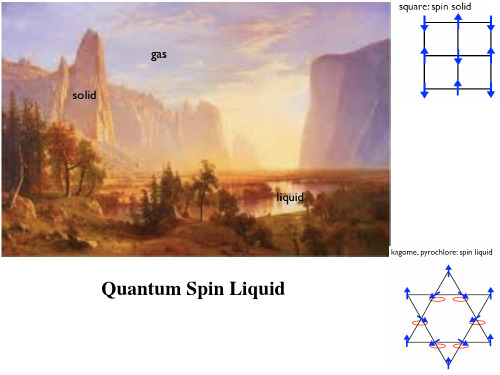
Square Lattice:
Td ~ 2CW Td ~ 0.75CW
Triangular Lattice:
•多重简并基态
Triangular Lattice
三角晶格:6重简并 2重简并(FM) Kagome Lattice
→AFM+Spin
Liquid
→AFM
例2:ZnCr2O4
AFM → Quasispin Glass
问题1:几何阻挫磁体是否存在亚铁磁体?
First experimental realization of spin Ladder with FM Legs
问题2:几何阻挫自旋玻璃与传统自旋玻璃区别?
PRL,106, 247202 (2011
1.ACr2O4 (A=Zn,Cd,Hg) 几何阻挫磁体(Tetragonal Lattice)
•Cr3+ 占据四面体顶角
•Cr3+ 自旋占据t2g轨道, 只有自旋—晶格耦合
Cd
Cr
c
b
a
•强磁场诱导磁相变
强磁场调制“自旋—晶格”耦合
Orthorhombic(Fddd)
量子临界行为
磁场诱导量子相变
?
?
Magnetic Field-induced quantum phase transition: 概念:Noncollinear spin structure ———— Collinear spin Structure (First Order Transition) Example: Pyrochlore Lttice
BS EN 1149-1-1996防护服 静电性能 第1部分表面电阻(试验方法和要求)

Copyright European Committee for Standardization Provided by IHS under license with CEN No reproduction or networking permitted without license from IHS
Engineering Equipment and Materials Users’ Association
Ergonomics Society Fabric Care Research Association Ltd. Heaith and Safety Executive Home Office Institub of Occupational Hygienists Instituteof Waste Management Iron and Steel “kadesConfederation London Regional lhnsport Madeup Textiles Association Minishy of Defence National Joint Council for Building Industxy (Operatives Side) Safety Equipment Association SATRA Footwear Technology Centre Textile Distributors’ Association Textile Services Association LM. M e s Union Congress
This European Standard was approved by CEN on 199509-09. CEN members are bound to comply with the CENEENELEC ink& Regulations which stipuiak the conditions for giving this European Standard the status of a national standard w+?out any alteration.
机械应力对锂离子电池性能的影响
byHyoncheol KmA dissertation submitted in partial fulfillment of the requirements for the degree of Doctor of Philosophy (Mechanical Engineering) in The University of Michigan 2009
Doctoral Committee: Professor Ann Marie Sastry, Chair Professor James R. Barber Associate Professor Christian M. Lastoskie Associate Professor Wei Lu
©
Hyoncheol Kim 2009 All Rights Reserved
€
To My Parents
ii
ACKNOWLEDGEMENTS
First of all, I would like to thank Prof. Ann Marie Sastry for her guidance and support. I was lucky to have her as my advisor because I have learned not only how to solve problems in science and technology from her great expertise, but also and more importantly how we can contribute to the world with what we can do for the better future. Her enthusiasm toward life and work is the most valuable thing I have learned at school and will always guide me throughout my life and career. Many thanks go to my committee members, Prof. James R. Barber, Prof. Christian M. Lastoskie, and Prof. Wei Lu for serving on my committee and providing your valuable advices on my thesis. I am very grateful to all of our current and former group members, Dr. Myounggu Park, Mr. Xiangchun Zhang, Mr. Myoungdo Chung, Mr. Min Zhu, Mr. Sangwoo Han, Mr. Dong Hoon Song, Ms. Qiuye Jin, Dr. Chia-Wei Wang, Dr. Munish V. Inamdar, Dr. Fabio Albano, Dr. Yenhung Chen, Dr. Kimberly Cook, Dr. Yun-Bo Yi, Dr. Taeyong Kim, Ms. Tahira Reid, and Mr. Peter Verhees for their support and sharing the wonderful moments for the past years. I also would like to thank my friends, Jiwon, Chi-Shan, Jung Kap and Jong-Hoon for their help and encouragement. Most importantly, I would like to thank my parents Ip Kwon Kim and Bup Jin Song, and my sister Hyun Hee for their love and support. I also would like to thank my parents in-law, Jeong Hong Chung and Myung Sook Lee, and
新陈代谢总论和生物氧化课件
COOH CH2 CH2 COOH
COOH
CH
+
CH
COOH
2H+ + 2e-
醇alcohol脱氢
乳酸脱氢酶lactate dehydrogenase
OH
CH3CHCOOH NAD+
O CH3CCOOH NADH
(2)water as reatant
酶催化的醛氧化成酸的反应即属于这一类。
H
H
一 Metabolism outline
(一) definition
生物小分子合成为
anabolism
生物大分子
(同化作用)
新陈代谢
需要能量 释放能量
能量 代谢
物质代谢
catabolism (异化作用) 生物大分子分解为
生物小分子
Common characteristics of metabolism reactions:
1. 由酶催化,反应条件温和。 2. 诸多反应有严格的顺序,彼此协调。 3. 对周围环境高度适应。
(二) research methonds 1. 活体内(in vivo)与活体外实验(in vitro) 2. 同位素示踪 isotopic tracing 3. 代谢途径阻断 blocking up
催化还原型QH2的氧化和细胞色素c(cyt.c)的还原。
QH2-cyt.c 还原酶 QH2 + 2 cyt.c (Fe3+) ==== Q + 2 cyt.c (Fe2+) + 2H+
主要包括细胞色素b 和c1,铁硫蛋白(2Fe-2S)。
cytochrome
细胞色素是一类含有血红素辅基(heme)的电子传 递蛋白质的总称. 线粒体呼吸链中主要含有细胞色素a, b, c 和c1 还原型细胞色素具有明显的可见光谱吸收。 细胞色素主要是通过Fe3+ Fe2+ 的互变起传递 电子的作用的。
模态应变能法计算方法
Revised Modal Strain Energy Method for Finite Element Analysis of Viscoelastic Damping Treated StructuresYanchu Xu, Yanning Liu, and Bill WangMaxtor Corporation, 500 McCarthy Blvd, Milpitas, CA 95035ABSTRACTIn traditional modal strain energy method, the real eigen-vector of each mode obtained from finite element analysis of the corresponding undamped structure is used to calculate modal strain energy in each material layer, and an iterative approach is used in dealing with the frequency dependency of viscoelastic materials. In this paper, a revised modal strain energy method is presented to significantly improve analysis accuracy of the structural natural frequencies and modal loss factors when the material loss factor is high, and a simplified approach is recommended to replace the iterative analysis to avoid tremendous amount of computational effort.Keywords: modal strain energy method, finite element analysis, damping, modal analysis1. INTRODUCTIONIn structural noise and vibration control, damping treatments have found more and more applications. Among a variety of damping mechanisms, such as from fluid viscosity, from friction in fibrous materials, etc., viscoelastic materials remain to be the favorite choices for the most effective damping treatments. Numerous successful cases applying viscoelastic damping to control structural noise and vibration can be found in applications from aerospace structures to hard disk drives. These applications normally involve bonding a relatively stiff thin member, also called constraining layer, to sheet metal structure with a soft viscoelastic material such that strain is induced in the adhesive during vibration. To analyze the dynamic performance of the damping treatments, considerable effort has been devoted to the studies of dynamic characteristics of viscoelastically damped structures [1]. There are two major approaches in the analysis of damping effect: analytical and numerical.The analytical approach is usually applicable to relatively simple structures, such as sandwich beams and plates, etc. The earliest analytical work on damping analysis can be found mostly related to the viscoelastic material property characterization. To develop an understanding of the parameters in the constrained layer damper, Ross, Kerwin and Unger [2] outlined the dominant design parameters for the case where all layers vibrate with the same sinusoidal spatial dependence. The outer layers are assumed to deform as Eular-Bernoulli beams and the adhesive is assumed to deform only in shear, which leads to a single fourth order beam equation where the equivalent complex bending stiffness depends on the properties of the three layers. To extend Ross, Ungar and Kerwin’s analysis to beams with general boundary conditions in which sinusoidal spatial dependence cannot be assumed, Mead etc.[3] obtained a sixth order equation of motion. It is assumed that the beam’s deflection is small and uniform across a section, the axial displacements are continuous, the base and constraining layers bend according to the Eular hypothesis, the damping layer deforms only in shear, and the longitudinal and rotary inertia effects are insignificant. The validity of the analysis is therefore limited to some upper range of core stiffness. Miles etc.[4] obtained a sixth order equation of motion by using Hamilton’s principal. The assumptions were equivalent to those of Mead except that relative transverse deflection is permitted between the outer layers and longitudinal inertia is included.Though analytical methods are useful for predicting damping characteristics of some simple structures, a numerical approach, mainly finite element method, remains to be the method of choice when complex physical systems are analyzed. In the finite element analysis of structures with visco-elastic damping material treatment, there are two issues making the analysis a tough task. One is that the modulus of a viscoelastic material is normally complex, however, most commercial finite element packages are not designed to deal with complex modulus efficiently and accurately. The other Smart Structures and Materials 2002: Damping and Isolation, Gregory S. Agnes,one is that the material properties of viscoelastic material are frequency dependent that creates a non-linear eigenproblem for the dynamic analysis. To deal with the complex modulus of the viscoelastic material, several different techniques have been developed, of which modal strain energy method has become a commonly used approach. In the modal strain energy method, the structure is first assumed to be undamped and modeled using the real part of complex modulus as the modulus of the damping layer. The real eigen-vectors of each mode are obtained from finite element analysis and strain energies in all layers of the structure are calculated. The dissipative energy of the structure is calculated proportional to the strain energy in the damping layer and the material loss factor, and the modal loss factor is obtained by calculating the ratio of the dissipative energy to the total structural energy. However, modal strain energy method becomes quite inaccurate when the damping of the structure becomes high. To consider the frequency and temperature dependence of elastic modulus of viscoelastic material, an iterative method is normally combined with commercial finite element software, which requires tremendous amount of computational effort since for each mode, eigen-solutions need to be repeated until converged results are obtained.In this paper, a revised modal strain energy method is presented. An equivalent modulus, the magnitude of the complex modulus, is used for the finite element modal analysis to obtain real eigen-vector. The strain energy and dissipative strain energy are calculated proportional to that of equivalent modulus, and the modal loss factor is calculated accordingly. The results are compared to direct complex eigen-solution and the accuracy of the modal strain energy method is found improved significantly. In replacing the iterative analysis, a simplified approach is proposed to avoid tremendous amount of computational effort, which has the most significant advantage in viscoelastic material selection. .2. MODAL STRAIN ENERGY METHODWhen a structure with viscoelastic damping treatment is to be analyzed, finite element modeling procedure can be used to establish its mass matrix [M], and stiffness matrix [K]. The structural eigen-value problem can be written as,[]{}[]{}0=+x K x M (1)where []M is a real matrix, and [][][]i r K i K K += a complex matrix due to the complex modulus of the viscoelastic damping material used in the structure.However, there are two issues associated with the eigen-problem of (1). One is that most commercial finite element software does not have the corresponding solver for the complex eigen-solution for a damped structure. Another one is that the modulus and loss factor of the viscoelastic material are frequency/temperature dependent, which results in the eigen-problem of (1) being a non-linear one.Modal strain energy method is one of the economical approaches in dealing with the complex modulus of the damping material. It assumes that the damped structure has the same natural frequencies and modal shapes as the undamped structure, thus the eigen-problem of the undamped structure is written as,[]{}[]{}0=+x K x M r(2)By solving (2), eigen-values and eigen-vectors, {},...3,2,1,,=r f r r φ can be obtained. For the rth mode, the dissipated and strain energies are defined as,{}[]{}{}[]{}rrTrSrr i Tr D r K EK E φφφφ== (3)The damping loss factor for the rth mode, r ζ, therefore becomes,{}[]{}{}[]{}rr T r r i Tr S r D r r K K E E φφφφζ==(4)Since damping modulus can be expressed as G i )1(η+, where G is the shear storage modulus of the viscoelastic material, and η is the material loss factor, and in finite element analysis, the strain energy in the viscoelastic materiallayer, VrE , can be also calculated, thus the damping loss factor of the rth mode can be estimated [5] as,Sr Vr r r E E ηζ=(5)where r ηis the material loss factor at the natural frequency of the rth mode. Xu [6] etc. compared the result for a cantilever sandwich beam using above mentioned modal strain energy method with that from direct complex eigen-solution using compound beam element, and found that results from both methods are very close when the material loss factor is low, however, significantly different when the material loss factor becomes high.However, due to viscoelastic materials ’ frequency dependent feature of the storage shear modulus G and loss factor η, as shown in Figure 1, the structural stiffness matrix in (1) is not only a complex one, but also in theory a function of frequency. Therefore, the dynamic characterization of a damped structure has not completed yet by the simple application of the modal strain energy method as outlined above. The storage shear modulus G and loss factor η of viscoelastic material are also temperature dependent, however, it is not going to be considered here since in most dynamic analysis, constant temperature could be assumed.Then the []r K in (2) is varies with the frequency of the interested mode. The modal analysis of the non-linear eigen-problem (2) can be normally simplified to an iterative process. For the modal parameters ,,r r f ηand {}r φof the rthmode, the method can be summarized as,Figure 1. Material Moduls and Loss Factor vs. Frequency at Different Temperature 1010010001000010100100010000Frequency (Hz)S h e a r S t o r a g e M o d u l u s - G (p s i )0.40.711.3L o s s F a c t o r - ηShear Storage Modulus (70F)Shear Storage Modulus (100F)Loss Factor (70 F)Loss Factor (100 F)Initialize: 0f f =, find the corresponding ()0f G G = , and calculate []()[]0f K K r r = For ,...3,2,1=kSolve: []{}[]{}0=+x K x M r Î ,,)()(k r k r f η and {})(k r φ If ε≤−)()(/k r k r f f f Î StopUpdate: )(k r f f =, find the corresponding ())(k r f G G =, and calculate []()[])(k r r r f K K =As the iteration continues, the estimated ,,)()(k r k r f η and {})(k r φwill converge to their exact solution ,,r r f ηand {}r φ. Similarly, modal parameters of other modes can be determined. This iterative process requires tremendous amount of computational effort. Especially in the process of viscoelastic material selection, this process needs to be repeated for each material trial.3. REVISED MODAL STRAIN ENERGY METHOD AND SIMPLIFIED PROCESSAs mentioned above, the traditional modal strain energy method uses the real eigen-vector of each mode obtained from finite element analysis of the corresponding undamped structure to calculate strain energy in each material layer. The dissipative energy is calculated proportional to the strain energy in the viscoelastic damping material layer and the material loss factor. The modal loss factor is then obtained by calculating the ratio of the dissipative energy to the total structural strain energy. The problem associated with this approach is that the errors in natural frequency and modal loss factor estimation increase dramatically when the material loss factor increases. The reason is that traditional modal strain energy method uses real part of the material modulus in the finite element analysis such that the natural frequencies don ’t change with material loss factor. A revised modal strain energy method will be discussed here first.In order to consider the effect of material loss factor on the structural natural frequencies, it is suggested to use an equivalent modulus, the magnitude of the viscoelastic material modulus, i.e. 21'η+=G G instead of G , in the undamped structural modal analysis, and use the resulting natural frequencies as the ones of the damped structure.When the equivalent modulus as shown in Figure 2 is used, the natural frequencies of the structure will increase with the loss factor even when the storage modulus of the viscoelastic material keeps the same, which agrees with what wasFigure 2. Material Modulus, Loss Factor and Equivalent Modulus 1010010001000010100100010000Frequency (Hz)S h e a r S t o r a g e M o d u l u s - G (p s i )E q u i v a l e n t M o d u l u s (p s i )0.40.711.3L o s s F a c t o r - ηShear Storage Modulus (70F)Equivalent Modulus (70 F)Loss Factor (70 F)verified by Xu [6] etc. using direct complex eigen-solution. After the modal analysis of the undamped system finished, the strain energies in different materials can be calculated accordingly. To estimate the modal loss factor, the strain energy and dissipative energy in the viscoelastic material need to be obtained differently as follows,Vr VD r Vr VS r E E E E 22111ηηη+=+=(6)where, VrE is the total strain energy of the rth mode in the viscoelastic material by assuming its modulus to be 'G . If the strain energy in all other material is O r E , then the modal loss factor of the rth mode can be estimated by,VSrO r VDr r E E E +=ζ (7)Also, due to the frequency dependency, the dynamic characterization of the damped structure normally needs an iteration process as stated in Section 2. To avoid the tremendous computational effort in solving the non-linear eigen-problem, a simplified process is proposed as follows,1. For viscoelastic materials to be evaluated, estimate the maximum and minimum modulus, /max G and /min G2. Starting from /minG , perform FEM analysis to obtain all natural frequencies and strain energies in all layers for different equivalent modulus in incremental 'G ∆ until /max G .3. Plot structural dynamic characteristic curves: natural frequency curves of all interested modes against the equivalent modulus as shown in Figure 3a); strain energy curves in different materials of all modes verse frequency as shown in Figure 3b).4. For different materials or material at different temperatures, repeat the following: a. Plot curves of material equivalent modulus and loss factor against frequency onto Figure 3a), as shown in Figure 3c). b. Find intersection of the material modulus curve with the natural frequency curve of each mode, ,...3,2,1,,'=r G f r r , to determine the natural frequency and the material loss factor from the corresponding frequency, ,...3,2,1,,=r f r r η, as shown in Figure 3c)c. Determine the strain energies in different materials for each natural frequency, ,...3,2,1,,=r E E Vr O r as shown in Figure 3d).d. Calculate modal loss factor by,,...3,2,1,12=++=+=r E E E E E E Vr r O r V r r VS r O r VDr r ηηζ (8)It is obvious that the simplified process requires only limited number of structural FEM analysis, so it can avoid the tremendous amount of computational effort due to the iterative process. Furthermore, after the limited FEM analysis, it doesn ’t require any more FEM analysis when other materials or the same material at different temperatures need to be evaluated as in material selection, which will result in significant computational cost saving.a)b)c)d)Figure 3. Simplified Process for Modal Analysis of Viscoelastically Damped Structuresa) Structural dynamic characteristic curves: f r , r=1,2,3,… b) Strain energy curves: E r V , E r O , r=1,2,3,…c) Finding natural frequency, material modulus and loss factor for specificviscoelastic materiald) Determining strain energies in viscoelastic material and other materialsand calculating modal loss factorf 1f 2f 3f 4f 5f 6f 71010010001000010100100010000Frequency (Hz)V i s c o e l a s t i c S h e a r M o d u l u s (p s i )E 1OE 2OE 3OE 4O E 5OE 6OE 7OE 1VE 2V E 3VE 4VE 5VE 6VE 7V00.20.40.60.8110100100010000Frequency (Hz)M o d a l S t r a i n E n e r g yG'G(f , G ')(f ,G ')ηf 1=22.4801=1.18f 2=190.042=1.101010010001000010100100010000Frequency (Hz)M o d u l u s (p s i )00.511.5M a t e r i a l L o s s F a c t o rf 1=22.4801=0.149E 1V =0.182E 1O =0.818f 2=190.042=0.167E 2V =0.211E 2O =0.7890.20.40.60.8110100100010000Frequency (Hz)M o d a l S t r a i n E n e r g y4. CASE STUDYTo demonstrate how much the revised modal strain method improves the accuracy of natural frequency and modal loss factor estimation of a damped structure, two sandwich beam samples of 10” long with different boundary conditions are given in Figure 4. Layers 1 and 3 are identical metal beams of 0.06” thick with Young ’s modulus of 30x106 psi, layer 2 is a soft core of 0.002” thick with material property as shown in Figure 1. Only one metal layer of beam (a) is clamped at one end while both metal layers of beam (b) are clamped at one end. The two samples are analyzed using direct complex eigen-analysis based on the compound beam element [6], the conventional modal strain energy method, and the revised modal strain energy method proposed in this paper.Both beams are evaluated for a viscoelastic material at temperatures of 70F and 100F. Figure 3 indicates the process for beam (a) at 70F using revised modal strain energy method, where the viscoelastic material equivalent modulus is from Figure 2. Table 1 shows the comparison of three methods for beam (a) and Table 2 the comparison for beam (b). In the tables, the solutions from direct complex eigen-solution are used as reference, to which the results from conventional and revised modal strain energy methods are compared. It is shown that the revised method significantly improves the accuracy for modal loss factor estimations.Note: Values after / in both Table 1 and 2 indicate percentage differences of both modal strain energy methods relative to direct complex eigen-solution10"10"(a)(b)123Figure 4. Sandwich beams with different boundary conditions Table 1. Natural frequency and modal loss factor comparison for sandwich beam (a) Table 2. Natural frequency and modal loss factor comparison for sandwich beam (b) f r ζr f r ζr f r ζr f r ζr f r ζr f r ζr122.1730.163120.7850.113121.603/-2.57%0.1888/15.74%20.351/-2.09%0.1220/7.87%22.480/1.38%0.1487/-8.85%20.871/0.41%0.1033/-8.66%2187.330.1710161.310.2450180.83/-3.47%0.2654/55.18%153.63/-4.76%0.3079/25.65%190.04/1.45%0.1674/-2.12%164.06/1.71%0.2277/-7.08%3529.160.2040445.800.2574510.94/-3.44%0.2811/37.83%425.86/-4.47%0.2941/14.28%538.12/1.69%0.1987/-2.57%454.20/1.88%0.2391/-7.10%41,025.40.2168866.790.2500989.68/-3.48%0.2745/26.63%829.04/-4.36%0.2719/8.77%1,040.0/1.42%0.2096/-3.31%879.41/1.46%0.2322/-7.11%51,647.40.22011,400.20.23851,605.3/-2.55%0.2611/18.61%1,362.8/-2.67%0.2523/5.80%1,679.8/1.97%0.2111/-4.11%1,438.0/2.70%0.2219/-6.95%62,397.30.21792,116.10.22602,345.0/-2.18%0.2456/12.69%2,023.6/-4.37%0.2348/3.90%2,443.1/1.91%0.2074/-4.84%2,121.4/0.25%0.2095/-7.29%73,284.80.21162,892.80.21303,199.0/-2.61%0.2291/8.25%2,805.4/-3.02%0.2170/1.87%3,318.6/1.03%0.1999/-5.54%2,926.4/1.16%0.1969/-7.57%ModeDirect Complex Eigen-solution Conventional Modal Strain Energy Method Revised Modal Strain Energy Method 70F 100F 70F 100F 70F 100Ff r ζr f r ζr f r ζr f r ζr f r ζr f r ζr134.0810.204629.1280.269132.576/-4.41%0.3347/63.61%27.923/-4.14%0.3480/29.32%34.757/1.98%0.2011/-1.70%29.974/2.90%0.2590/-3.76%2199.270.2425166.170.2486189.69/-4.81%0.3253/34.17%159.12/-4.24%0.2892/16.31%202.66/1.70%0.2312/-4.64%169.68/2.11%0.2340/-5.89%3552.850.2338459.200.2590530.23/-4.09%0.3041/30.06%439.19/-4.36%0.2904/12.12%561.92/1.64%0.2262/-3.26%468.37/2.00%0.2430/-6.18%41,053.00.2342883.050.25111,015.6/-3.55%0.2879/22.94%847.84/-3.99%0.2689/7.08%1,070.7/1.68%0.2262/-3.41%899.22/1.83%0.2342/-6.73%51,690.20.23041,439.00.23781,638.3/-3.07%0.2683/16.43%1,389.4/-3.45%0.2488/4.64%1,717.2/1.60%0.2212/-4.01%1,464.5/1.77%0.2215/-6.84%62,445.00.22422,145.50.22492,384.6/-2.47%0.2496/11.32%2,057.6/-4.10%0.2318/3.09%2,486.5/1.70%0.2136/-4.73%2,155.9/0.49%0.2089/-7.09%73,297.50.21562,918.90.21163,245.5/-1.58%0.2314/7.33%2,847.4/-2.45%0.2142/1.24%3,368.4/2.15%0.2039/-5.43%2,968.7/1.71%0.1960/-7.36%100F 70F 100F Direct Complex Eigen-solution Mode 70F 100F 70F Conventional Modal Strain Energy Method Revised Modal Strain Energy Method5. CONCLUSIONViscoelastic damping treatment has found more and more applications as an effective means of passive noise and vibration control. However, dynamic characterization of the damped structures has been a difficult task, especially in the finite element analysis, due to both complex modulus and frequency dependency of viscoelastic material property. In dealing with the complex modulus, conventional modal strain energy method uses the real eigen-vector of the undamped structure to calculate modal strain energy, and then the modal loss factor is calculated accordingly, this approach can’t give an accurate estimation when the material loss factor is high. To consider the frequency dependency, an iterative process is normally required when commercial finite element analysis software is used, which takes tremendous amount of computational effort.The revised modal strain energy method presented in this paper significantly improves analysis accuracy of the structural natural frequencies and modal loss factors when the material loss factor is high. And the simplified approach for dealing with the frequency dependency can be utilized to avoid tremendous amount of computational effort, which is especially powerful in viscoelastic material selection.REFERENCES1. A. D. Nashif, D. I. G. Jones, J. P. Henderson, Vibration Damping, John Wiley & Sons, New York, 19852. D. Ross, E. E. Ungar and Jr. E. M. Kerwin, “Damping of Flexural Vibrations by Means of Viscoelastic Laminates”,Structural Damping, ASME, New York, 19593. D. J. Mead, S. Markus, “The Forced Vibration of a Three-Layer, Damped Sandwich Beam with Arbitrary BoundaryConditions,” 1969, Journal of Sound and Vibration, Vol. 10(2), pp. 163-1754. R. N. Miles, and P. G. Reinhall, “An analytical model for the vibration of laminated beams including the effects ofboth shear and thickness deformation in the adhesive layer”, Journal of Vibration, Acoustics, Stress, and Reliability in Design, Vol. 108, pp. 56-64, 19865. ANSYS Theory Manual for Revision 5.5.6. Y. Xu, D. Chen, “Finite Element Modeling for the Flexural Vibration of Damped Sandwich Beams ConsideringComplex Modulus of the Adhesive Layer,” Proceedings of SPIE, vol. 3989, Damping and Isolation, pp. 121-129, Newport Beach, California, 2000。
Liquid_Exfoliation_of_Layered_Materials
DOI: 10.1126/science.1226419, (2013);340 Science et al.Valeria Nicolosi Liquid Exfoliation of Layered MaterialsThis copy is for your personal, non-commercial use only.clicking here.colleagues, clients, or customers by , you can order high-quality copies for your If you wish to distribute this article to othershere.following the guidelines can be obtained by Permission to republish or repurpose articles or portions of articles): July 3, 2013 (this information is current as of The following resources related to this article are available online at/content/340/6139/1226419.full.html version of this article at:including high-resolution figures, can be found in the online Updated information and services, /content/340/6139/1226419.full.html#ref-list-1, 8 of which can be accessed free:cites 136 articles This article/cgi/collection/chemistry Chemistrysubject collections:This article appears in the following registered trademark of AAAS.is a Science 2013 by the American Association for the Advancement of Science; all rights reserved. The title Copyright American Association for the Advancement of Science, 1200 New York Avenue NW, Washington, DC 20005. (print ISSN 0036-8075; online ISSN 1095-9203) is published weekly, except the last week in December, by the Science o n J u l y 3, 2013w w w .s c i e n c e m a g .o r g D o w n l o a d e d f r o mThe list of author affi liations is available in the full article online.*Corresponding author. E-mail: colemaj@tcd.ieLiquid Exfoliation of Layered MaterialsValeria Nicolosi, Manish Chhowalla, Mercouri G. Kanatzidis, Michael S. Strano, Jonathan N. Coleman*Background: Since at least 400 C.E., when the Mayans fi rst used layered clays to make dyes, people have been harnessing the properties of layered materials. This gradually developed into scientifi c research, leading to the elucidation of the laminar structure of layered materials, detailed understand-ing of their properties, and eventually experiments to exfoliate or delaminate them into individual, atomically thin nanosheets. This culminated in the discovery of graphene, resulting in a new explosion of interest in two-dimensional materials.Layered materials consist of two-dimensional platelets weakly stacked to form three-dimensional structures. The archetypal example is graphite, which consists of stacked graphene monolayers. How-ever, there are many others: from MoS 2 and layered clays to more exotic examples such as MoO 3, GaTe, and Bi 2Se 3. These materials display a wide range of electronic, optical, mechanical, and electrochemi-cal properties. Over the past decade, a number of methods have been developed to exfoliate layered materials in order to produce monolayer nanosheets. Such exfoliation creates extremely high-aspect-ratio nanosheets with enormous surface area, which are ideal for applications that require surface activity. More importantly, however, the two-dimensional confi nement of electrons upon exfoliation leads to unprecedented optical and electrical properties.Advances: An important advance has been the discovery that layered crystals can be exfoliated in liquids. There are a number of methods to do this that involve oxidation, ion intercalation/exchange, or surface passivation by solvents. However, all result in liquid dispersions containing large quantities of nanosheets. This brings considerable advantages: Liquid exfoliation allows the formation of thin fi lms and composites, is potentially scaleable, and may facilitate processing by using standard technologies such as reel-to-reel manufacturing.Although much work has focused on liquid exfoliation of graphene, such processes have also been demonstrated for a host of other materials, including MoS 2 and other related structures, lay-ered oxides, and clays. The resultant liquid dispersions have been formed into fi lms, hybrids, and composites for a range of applications.Outlook: There is little doubt that the main advances are in the future. Multifunctional composites based on metal and polymer matrices will be developed that will result in enhanced mechanical, electrical, and barrier properties. Applications in energy generation and storage will abound, with layered materials appearing as electrodes or active elements in devices such as displays, solar cells, and batteries. Particularly impor-tant will be the use of MoS 2 for water splitting and metal oxides as hydrogen evolution catalysts. In addition, two-dimensional materials will fi nd important roles in printed electronics as dielectrics, optoelectronic devices, and transistors.To achieve this, much needs to be done. Production rates need to be increased dramatically, the degree of exfoliation improved, and methods to control nanosheet properties devel-oped. The range of layered materials that can be exfoliated must be expanded, even as methods for chemical modifi cation must be developed. Success in these areas will lead to a family of materials that will dominate nanomaterials science in the 21st century.21 JUNE 2013 VOL 340 SCIENCE 1420ARTICLE OUTLINE Why Exfoliate?Large-Scale Exfoliation in Liquids?PioneersRecent Advances in Liquid Exfoliation Potential Applications of Liquid-Exfoliated Nanosheets OutlookADDITIONAL RESOURCESJ. N. Coleman et al ., Two-dimensional nanosheets produced by liquid exfoliation of layered materials. Science 331, 568–571 (2011). doi:10.1126/science.1194975K. Varoon et al ., Dispersible exfoliated zeolite nanosheets and their application as a selective membrane. Science 334, 72–75 (2011). doi:10.1126/science.1208891READ THE FULL ARTICLE ONLINE /10.1126/science.1226419Liquid exfoliation of layered crystals allows the production of suspensions of two-dimensional nanosheets, which can be formed into a range of structures. (A ) MoS 2 powder. (B ) WS 2 dispersed in surfactant solution. (C ) An e xfoliate d MoS 2 nanosheet. (D ) A hybrid material consisting of WS 2 nanosheets embedded in a network of carbon nanotubes.Published by AAASo n J u l y 3, 2013w w w .s c i e n c e m a g .o r g D o w n l o a d e d f r o mLiquid Exfoliation of Layered Materials Valeria Nicolosi,1,2Manish Chhowalla,3Mercouri G.Kanatzidis,4Michael S.Strano,5Jonathan N.Coleman1*Not all crystals form atomic bonds in three yered crystals,for instance,are those that form strong chemical bonds in-plane but display weak out-of-plane bonding.This allows them to be exfoliated into so-called nanosheets,which can be micrometers wide but less than a nanometer thick.Such exfoliation leads to materials with extraordinary values of crystal surface area,in excess of1000square meters per gram.This can result in dramatically enhanced surface activity,leading to important applications,such as electrodes in supercapacitors or batteries. Another result of exfoliation is quantum confinement of electrons in two dimensions,transforming the electron band structure to yield new types of electronic and magnetic materials.Exfoliated materials also have a range of applications in composites as molecularly thin barriers or as reinforcing or conductive fillers.Here,we review exfoliation—especially in the liquid phase—as a transformative process in material science,yielding new and exotic materials,which are radically different from their bulk,layered counterparts.I n1824,Thomas H.W ebb heated a mineral sim-ilar to mica and,by means of thermal ex-foliation,transformed it into what is today a valuable commodity,with applications as an ion exchange resin,an insulating material,and a structural binder in cement.He named the mineral“vermiculite”for its wormlike appear-ance upon exfoliation(Fig.1),from the Latin vermiculare meaning“to breed worms.”Almost 200years later,in2004,Geim and Novosolov showed that thin transparent adhesive tape could be used to exfoliate graphite into single atomic layers of graphene and demonstrated atomical-ly thin devices(1).As a process,exfoliation of layered solids has had a transformative effect on materials science and technology by opening up properties found in the two-dimensional(2D) exfoliated forms,not necessarily seen in their bulk counterparts.Layered materials are defined as solids with strong in-plane chemical bonds but weak out-of-plane,van der Waals bonds.Such materials can be sheared parallel or expanded normal to the in-plane direction.In the extreme limit,these processes yield nanometer-thin—even atomically thin—sheets that are not at all characteristic of the bulk precursor.This production of extremely thin sheets from layered precursors is known as exfoliation or delamination,although in this work we will use the former term.The sheets produced are generally referred to as nanosheets, where“nano”refers to the magnitude of the thick-ness.Although in the ideal case such nanosheets consist of single monolayers,they are often man-ifested as incompletely exfoliated flakes compris-ing a small number(<10)of stacked monolayers.There are many types of layered materials,whichcan be grouped into diverse families(Fig.1).The simplest are the atomically thin,hexagonalsheets of graphene(1–3)and hexagonal boronnitride(h-BN)(4).Transition metal dichalco-genides(TMDs)(such as MoS2and WSe2)(5,6)and metal halides(such as PbI2and MgBr2)(7)have near-identical structures and consist ofa plane of metal atoms sandwiched betweenplanes of halide/chalcogen yered me-tal oxides(such as MnO2,MoO3,and LaNb2O7)(8–11)and layered double hydroxides(LDHs)[such as Mg6Al2(OH)16](8,12)represent a di-verse class of materials with a large variety ofstructures.Similarly,layered silicates,or clays,are minerals and exist as many different types,with well-known examples being montmorilloniteor the micas(13,14).Generally,oxides,LDH,and clay nanosheets are charged and are accom-panied by charge-balancing ions(8,14).Otherinteresting families are the layered III-VIs(suchas InSe and GaS)(15),the layered V-VIs(such asBi2Te3and Sb2Se3)(16),the metal trichalcogenides,and metal trihalides.Although many other lay-ered materials exist(Table1),all share a planar,anisotropic bonding and therefore the potentialto be exfoliated into nanosheets.One substantial advantage of layered materi-als is their diversity.Even before exfoliation,themany families of layered materials display a verybroad spectrum of properties.For example,TMDs(5,6)occur as more than40different types de-pending on the combination of chalcogen(S,Se,or Te)and transition metal(5,6).Depending onthe coordination and oxidation state of the metalatoms,or doping of the lattice,TMDs can be me-tallic,semimetallic,or semiconducting(6).In ad-dition,these materials display interesting electronicbehavior,such as superconductivity or charge-density wave effects(6).Similarly,the many dif-ferent types of layered metal oxides have interestingelectronic,electrochemical,and photonic proper-ties(8).These materials have been fabricated intotransistors,battery electrodes,and magneto-opticdevices(8–10).Thus,even as bulk crystals,lay-ered materials are an interesting and potentiallyuseful material class.This makes them an excitingstarting material for exfoliation into nanosheets.As we will see below,exfoliation dramaticallyenhances the range of properties displayed by analready diverse material type.Why Exfoliate?The simplest effect of exfoliation is to dramati-cally increase the accessible surface area of amaterial.For surface-active or catalytic materials,this can radically enhance their chemical andphysical reactivity.The ion exchange ability ofminerals such as vermiculite to purify water at1000meq/kg depends on its near106-fold increasein surface area after expansion(13).In structuralmechanics,the strength and stiffness of compositesincrease as the thickness of planar fillers,such asclay or graphite,decreases(17).When heat causesexfoliation,a layered material can be used as anintumescent(or thermally expansive)material.Hence,vermiculite and graphite are used for fireretardation in paints and firestop pillows be-cause they reduce their density upon heating andproduce an ash of low thermal conductivity.As interest in nanotechnology has intensi-fied in recent decades,another important advan-tage of exfoliation has emerged.In a layeredcrystal,the electronic wave function extendsin three dimensions.However,after exfoliationelectrons are constrained to adopt a2D wavefunction,thus modifying the electronic bandstructure.Graphite can be transformed into agraphene monolayer after exfoliation,with elec-tronic properties that differ greatly from any othermaterial(1).These include an enormously highcarrier mobility and other exciting properties,such as Klein tunnelling and the half-integer quan-tum Hall effect(1,3).Likewise,the propertiesof MoS2depend strongly on exfoliation state.The bandgap of MoS2changes on exfoliationfrom1.3eV for the bulk crystal to1.9eV foran exfoliated nanosheet.Because the bandgapchanges monotonically with number of mono-layers per nanosheet,this allows the electronicresponse to be chosen at will(18).In addition,although multilayer MoS2is not photolumines-cent,exfoliation-induced changes in its electron-ic structure lead to photoluminescent behaviorin exfoliated monolayers(19).Similar behavioris expected in other layered semiconductors(5).Large-Scale Exfoliation in Liquids?The exfoliation of graphite demonstrated by Geimand Novolosov was achieved essentially by rubbinggraphite on a surface(1).Such mechanical ex-foliation remains the source of the highest-qualitygraphene samples available and has resultedin some major advances(1).However,it suffersfrom low yield and a production rate that is not1School of Physics and Centre for Research on Adaptive Nano-structures and Nanodevices,Trinity College,Dublin,D2Dublin,Ireland.2School of Chemistry,Trinity College,Dublin,D2Dublin,Ireland.3Materials Science and Engineering,Rutgers University,Piscataway,NJ08901,USA.4Department of Chemistry,North-western University,Evanston,IL60208,USA.5Department ofChemical Engineering,Massachusetts Institute of Technology,Cambridge,MA02139,USA.*Corresponding author.E-mail:colemaj@tcd.ie SCIENCE VOL34021JUNE20131226419-1o n J u l y 3 , 2 0 1 3 w w w . s c i e n c e m a g . o r g D o w n l o a d e d f r o mtechnologically scalable in its current form.One possible solution is the exfoliation of lay-ered compounds in liquids to give large quan-tities of dispersed nanosheets.This should allow for methods to obtain sizable quantities of 2D materials that can be processed by using exist-ing industrial techniques,such as reel-to-reel manufacturing.Here,we briefly outline the four main liquid exfoliation techniques for layered materials (schematics are provided in Fig.2,and examples of exfoliated nanosheets are pro-vided in Fig.3).One of the oldest methods of exfoliating lay-ered crystals with low reductive potential is oxi-dation and subsequent dispersion into suitable solvents.The best example is that of graphite (20),in which treatment with oxidizers such as sulphuric acid and potassium permanganate results in ad-dition of hydroxyl and epoxide groups to the basal plane.The resulting hydrophillicity allows water intercalation and large-scale exfoliation to yield graphene oxide upon ultrasonication.The dispersed flakes are predominantly monolayers,typically hundreds of nanometers across,and sta-bilized against reaggregation by a negative sur-face charge at concentrations of up to 1mg/ml.Dispersed graphene oxide can be chemically re-duced in the liquid phase but will then aggregate unless surfactant or polymer stabilizers are present.Although reduction removes most of the oxides,structural defects remain,rendering the properties of oxidatively produced graphene substantially different from pristine graphene.Layered materials can also strongly adsorb guest molecules into the spacing between lay-ers,creating what are called inclusion complexes.This forms the basis of another exfoliation meth-od that is widely applied to layered materials,including graphite (21)and TMDs (22,23).Intercalation,often of ionic species,increases the layer spacing,weakening the interlayer ad-hesion and reducing the energy barrier to exfolia-tion.Intercalants such as n -butyllithium (22,23)or IBr (21)can transfer charge to the layers,re-sulting in a further reduction of interlayer bind-ing.Subsequent treatment such as thermal shock (21)or ultrasonication (22,23)in a liquid com-pletes the exfoliation process.The exfoliated nanosheets can be stabilized electrostatically by a surface charge (23)or by surfactant addition (21).In the case of MoS 2,this method tends to give highly exfoliated nanosheets (22).However,ion intercalation –based methods have drawbacks associated with their sensitivity to ambient condi-tions (22–24).Ion exchange methods take advantage of the fact that LDHs,clays,and some metal oxidesFig.1.Crystalstructures,natural-ly occurring forms,and exfoliated products for four example layered materials.(A )Graphite consists of alternating stacks of hexagonally ar-ranged carbon atoms (black spheres),(B )is a naturally occurring mineral,and (C )exfoliates to single atomic layers of carbon called graphene.(D )Vermicu-lite is a layered silicate hydrate (typ-ically Mg 1.8Fe 0.9Al 4.3SiO 10(OH)2•4(H 2O)that (E )is found naturally as a min-eral and (F )can be exfoliated,for example,upon heating.Silicon atoms are in blue,oxygen atoms are in red,Al/Mg/Fe atoms are in yellow,and interlayer counterions are in black (H and H 2O not shown).(G )MoS 2is a layered arrangement of S and Mo atoms (chalcogen atoms are in yellow,and transition metal are in green)that (H )is found naturally as the mineral molybdenite and (I )can be exfoliated to MoS 2monolayers.(J )Layered manganese dioxide (man-ganese atoms are in yellow,oxygen is in red,and interlayer counterions are in black)occurs naturally (K )as birnessite and (L )can be exfoliated to give MnO 2nanosheets.(C),(I),and (L)are adapted from (48),(87),and (58),respectively.The layer spac-ings for each material are graphite,0.35nm;vermiculite,1.5nm;MoS 2,0.6nm;and MnO 2,0.45nm.21JUNE 2013VOL 340SCIENCE1226419-2REVIEWo n J u l y 3, 2013w w w .s c i e n c e m a g .o r g D o w n l o a d e d f r o mTable 1.Referenced table of families of layered compounds,including structures and information on exfoliation methods,potential applications,and availablility.This table is not exhaustive.Crystal structures were obtained from the CrystalMaker Library (/library/index.html).Graphi t eTop viewSide viewF amily of layered compound StructureExfoliation methodApplicationsCommercial availabilitySonication in surfactantsolution (30, 50–53)Sonication in solvents (27, 45–48)Sonication in polymersolutions (54, 55)Graphene oxide (20,88)Many (1, 89)Widely availableMoS 2top viewMoS 2 side viewSingle-layer transistor (92)Batteries (63, 64)Top-gatephototransistors (93)Thermo-electrics (29, 58)Superconducting composites (94)Raw materials mostly available (purity issues)h-BNTop viewNitrogen BoronSide viewSonication in surfactant solution (58)Sonication in solvents (29, 56)Sonication in polymer solutions (54)Sonication in surfactant solution (58)Sonication in solvents (29, 59, 60)Sonication in polymer solutions (54)Ion intercalation (91)Composites (57)Device substrates (90)YesTransition metal ChalcogenTransition metal dichalcogenides (TMDs) SCIENCE VOL 34021JUNE 20131226419-3REVIEWo n J u l y 3, 2013w w w .s c i e n c e m a g .o r g D o w n l o a d e d f r o mTiTe 3top viewMnPS 3top viewTiTe 3side viewMnPS 3 side viewBatteries (96)No, only by synthesisIon intercalation (95)Wide band-gap semiconductors (97)Magnetic properties (98)No, only by synthesisIntercalation (75)Transition metal ChalcogenTransition metal Chalcogen PhosphorusTransition metal trichalcogenides (TMDs)AMo 3X 3, NbX 3, TiX 3, and TaX 3 (X = S, Se, or Te)Metal phosphorous trichalcogenides (MPX 3), such as MnPS 3, CdPS 3, NiPS 3, ZnPS 3, and Mn 0.5Fe 0.5PS 321JUNE 2013VOL 340SCIENCE 1226419-4REVIEWo n J u l y 3, 2013w w w .s c i e n c e m a g .o r g D o w n l o a d e d f r o mtop viewCrCl PbCl top viewMoCl CrCl 3 side viewPbCl 4 side viewNo (synthesis required)No (synthesis required)No (synthesis required)Ion intercalation (7)Polymer intercalation(99)Ion intercalation (100)Polymer intercalation (99)Ion intercalation (101)Transition metal HalideTransition metal Heavy metal Halide AmmoniumMetal halidesTransition-metal dihalides*Metal MX 3 halides, such as αRuCl 3, CrCl 3, and BiI 3†Layer-type halides with composition MX 4, MX 5, MX 6‡MoCl 2 top 2 side view3top viewHalide SCIENCE VOL 34021JUNE 20131226419-5REVIEWo n J u l y 3, 2013w w w .s c i e n c e m a g .o r g D o w n l o a d e d f r o mNa x (Mn 4+,Mn 3+)2O 4(birnessite) top viewNa x (Mn 4+,Mn 3+)2O 4 (birnessite) side viewVanadium oxide (V 2O 5) top viewV 2O 5 side viewSome raw materials available (purity issues)Most compounds are not availableSupercapacitors (106)Batteries (107)Catalysts (108)Dielectrics (109)Ferroelectrics (109)Ti oxidesIon intercalation (102)Mn oxidesSonication in surfactantsolution (58); Ion intercalation (103)Nb oxidesIon intercalation (104)Va oxidesPolymer intercalation (105)Transition metal Oxygen CatonVanadium OxygenOxidesTransition metal oxides : Ti oxides, Ti 0.91O 2, Ti 0.87O 2, Ti 3O 7, Ti 4O 9, Ti 5O 11; Nb oxides,Nb 3O 8, Nb 6O 17, HNb 3O 8;§ Mn oxides, MnO 2, Ti 3O 7, Na x (Mn 4+,Mn 3+)2O 421JUNE 2013VOL 340SCIENCE 1226419-6REVIEWo n J u l y 3, 2013w w w .s c i e n c e m a g .o r g D o w n l o a d e d f r o mMoO 3top viewMoO 3 side viewSr 2RuO 4 top viewSr 2RuO 4 side viewYesNo (only by synthesis)No (only by synthesis)Ion intercalation (110)Polymer intercalation(111)Intercalation with liquid crystals (115)Ion intercalation (protonation and ion exchange) (116)Amine surfactant (TBA +) under sonication (117)Ion intercalation (protonation and ion exchange) (114)Electrochromics (112)Light emitting diodes (113)Ferroelectrics (118)Photochromic (119)Photoluminescent (120)Layered trirutile phases HMWO (M = Nb, Ta), such as (HNbWO 6 and HTaWO 6)Hydrogen OxygenTransition metal StrontiumRutheniumOxygenOxidesTrioxides, such as MoO 3, TaO 3, and hydrated WO 3Perovskites and niobates, such as Sr 2RuO 4KCa 2Nb 3O 10, H 2W 2O 7, LaNb 2O 7, La 0.90Eu 0.05Nb 2O 7, Eu 0.56Ta 2O 7, Sr 2RuO 4, Sr 3Ru 2O 7, SrTa 2O 7, Bi 2SrTa 2O 9, Ca 2Nb 3O 10, Sr 2Nb 3O 10, NaCaTa 3O 10, CaLaNb 2TiO 10, La 2Ti 2NbO 10, and Ba 5Ta 4O15 SCIENCE VOL 34021JUNE 20131226419-7REVIEWo n J u l y 3, 2013w w w .s c i e n c e m a g .o r g D o w n l o a d e d f r o mTi 2Sb 2O top viewTi 2Sb 2O side viewFeOCl top viewFeOCl side viewNo (only by synthesis)No (only by synthesis)To our knowledge, these have never been exfoliatedIon intercalation (122)Superconductivity (121)Magnetic properties (121)Catalyst (redox properties) (121)Batteries (121)Batteries (123)Transition metal Pnictide CationTransition metal Halide OxygenOxidesOxychalcogenides and oxypnictides: Oxychalcogenides, LaOCuCh(Ch, chalcogenide) and derivatives, Sr 2MO 2Cu 2-δS 2 (M = Mn, Co, Ni),Sr 2MnO 2Cu 2m -0.5S m +1 (m = 1-3), Sr 4Mn 3O 7.5Cu 2Ch 2 (Ch=S, Se); oxypnictides, LaOFeAs II Oxyhalides of transition metals, such as VOCl, CrOCl, FeOCl, NbO 2F, WO 2Cl 2, and FeMoO 4Cl 21JUNE 2013VOL 340SCIENCE 1226419-8REVIEWo n J u l y 3, 2013w w w .s c i e n c e m a g .o r g D o w n l o a d e d f r o mLayered ␣ and ␥ zirconiumphosphates and phosphonatesGaSe top viewGaSe side viewCaHPO 4 top viewCaHPO 4 side viewSome available (maybe purity issues), mostly synthesizedNo (only by synthesis)Ion intercalation (124)Surfactant (125)Nonlinear optical properties, poor thermal conductivity (126)Intercalation (127)Exfoliation in water/acetone mixtures (128)Drug delivery (127)Semiconductor for dye sensitized solar cells (129)S/Se/Te Ga/InOxygen Phosphorus Cation WaterIII–VI layered semiconductorGaX (X = S, Se, Te); InX (X = S, Se Te)¶α-M IV phosphates, α-M IV (O 3P–OH)2·H 2O; and α-Metal IV phosphonates, M IV (O 3P–R)2·n H 2O# o n J u l y 3, 2013w w w .s c i e n c e m a g .o r g D o w n l o a d e d f r o mVermiculite top viewVermiculiteside viewKaolite top viewKaolite side viewNatural minerals,available on themarket Dispersion in water(13)Intercalation (130)Polymer intercalation(131)Catalysis (130)Composites (131)Lightweightnanocomposites forstructural applications(132)Clay-dye complexesand photoactivematerials (131)Organoclays as ionicand electronicconductors (compositeswith conductivepolymers) (131)Thermal and barrierpropertiesnanocomposites (133)Aluminum Oxygen Silicon OH-Oxygen Silicon Cation Intercalates/-C/-OHClays(layered silicates)2:1 Layered silicates**:Smectites, M n+x/n.yH2O[Al4-xMgx](Si8)O20(OH)4;talc, [(Mg3)(Si2O5)2(OH)2];vermiculite, [Mg6.Si6Al2/O20(OH)4] [M n+1/n] (Mg6);biotite [(MgFe)3(Si3Al)O10(OH)2]K;phlogopite, [(Mg6)(Si6Al2)O20(OH)4]Ba;fluorphlogopite, [Mg11/4(Si6Al2)O20F4][(M2+)3/2;margarite, [(Al2)(Si2Al2)O10(OH)2]Ca;and muscovite, [(Al2)(Si3Al)O10(OH)2]K1:1 Layered Silicates ††: Kaolite,[Al4Si4O10](OH)8; halloysite,Al4Si4O10(OH)8.4H2OonJuly3,213www.sciencemag.orgDownloadedfromBrucite (Mg 2+x , Mg 3+x (OH)2 (A n–)x/n . yH 2O)top viewBrucite (Mg 2+x , Mg 3+x (OH)2 (A n–)x/n . yH 2O) side viewTi3C2No, only bysynthesisYesIntercalation (134)Surfactant-assistedexfoliation and intercalation ofmolecules (135)Surfactant exfoliation (136)Solvent exfoliation in DMF (137)Functionalizationfollowed by exfoliation in solvents (138)Biocompatible–bio-hybrids/drug delivery (12, 134)Bionanocomposites with functional and structural properties (139)Extra oxygen and hydrogen at layers surface are present as a consequence of the exfoliation treatment with HF (66, 67).Batteries andsupercapacitors (140)Carbon TitaniumOxygenHydrogenCationLayered double hydroxides (LDHs)Ternary transition metal carbides and nitridesGeneral formula: M(II)1–x M(III)x (OH)2(A n –)x /n . yH 2O, where M(II) = divalent cation; M(III) = trivalent cation; A = interlayer anion; and n – = charge on interlayer anion‡‡Derivatives from MAX phases, where M = transition metal; A = Al or Si;and X=C or N§§Oxygen Hydrogen*These are iso-structural with TMDs.†These are defect CdI2structure types.‡These are heavy metal halides (perovskite type)structurally similar to transition metal dihalides withorganic ammonium interlayers.§Protons emplaced between 2D of Nb 3O 8–anion nanosheets composed of NbO 6octahedra.‖They contain oxide layers separated by distinct layers,which contain the softer chalcogenide (S,Se,and Te)or pnictide (P,As,Sb,and Bi).¶The building block has a trigonal structure,consisting of a pair of (M 3X 3)rings linked by M –M yers interact through van der Waals forces between the X outermost planes.#R is an organic radical,and n is the number of water molecules that can be intercalated in the interlayer region.**The 2:1notation means that the layers consist of two tetrahedral silicate sheets sandwiching one octahedral sheet.††Layer consists of one tetrahedral silicate sheets and one octahedral sheet.‡‡The structure of LDHs can be described by considering Mg(OH)2,which consists of Mg 2+ions coordinated octahedrally by hydroxyl groups.The octahedral units share edges to form infinite,charge neutral layers.In an LDH,isomorphous replacement of a fraction of the Mg 2+ions with a trivalent cation,such as Al 3+,occurs and generates a positive charge on the layers that necessitates the presence of interlayer,charge-balancing,anions.The remaining free space of the interlayer is occupied by water of crystallization.§§Layered M 2X,M 3X 2,M 4X 3,where M =transition metal and X =C or N,can be obtained after removal of the A layer with hydrofluoric acid (HF).o n J u l y 3, 2013w w w .s c i e n c e m a g .o r g D o w n l o a d e d f r o m。