
PS管道混合器安装与使用说明书10版
唐山国华科技有限公司
2010 年 1 月 15 日
目录 一、概述……………………………………………………………1 二、结构特征………………………………………………………1 三、主要技术特征…………………………………………………4 四、外形及安装尺寸………………………………………………5 五、安装与调整……………………………………………………5 六、使用、操作……………………………………………………7 七、故障分析与排除………………………………………………8 八、保养、维护……………………………………………………8 九、运输、储存……………………………………………………9 十、开箱及检查……………………………………………………9 十一、联系方式……………………………………………………9
0.02Mpa;上方左右侧各有一个Ф1/2″(Ф15mm)管分别为捕收剂和
起泡剂进入管;右侧有二个Ф1/2″精细阀门,用于分别调节捕收剂
和起泡剂添加量;盘面上有二台超声波流量计,用专用磁棒切换显示
浮选剂的瞬时用量、累计用量和累计时间;中部有压力表显示乳化器
工作压力。溢流管管径为Ф11/2″;管道泵进出口内径均为Ф32mm。
图 7 PS 型煤浆预处理器系统安装示意图
(浮选入料自流进入浮选机的情况)
三、主要技术特征
表 1、表 2 和表 3 分别列出 PS 型煤浆预处理器的主要技术规格。
5
表 1 PS 型煤浆预处理器规格
型号
PS-200 PS-250 PS-300 PS-350 PS-400 PS-450 PS-500 PS-550 PS-600
最大处理能力 m3/h 100 150 250 350 450 550 700 850 1000
配用乳化器型号
AEM-Ⅰ(Ⅱ)
配用管道混合器型号 PM-200 PM-250 PM-300 PM-350 PM-400 PM-450 PM-500 PM-550 PM-600
总重量 kg
266.4 318.9 430.0 473.0 554.1 681.2 681.4 895.1 1082.6
压力表损坏,计量不准确 浮选剂乳化器上 压力表读数下降 喷嘴出口磨损
六、使用、操作
1.PM 型管道混合器的使用 PM 型管道混合器不论安装在浮选入料泵与浮选机入料箱的管路 中,还是浮选入料自流进入混合器,必须保证混合器入口处有≥ 0.05MPa 的压头,为此建议在入口处安装量程为 0.1MPa 的压力表。 当浮选入料中有大量杂物有可能堵塞流体混合单元通道,因此必 须安装滤水除杂装置,并定期清理。 2.AEM 型浮选剂乳化器的使用 ⑴ 为了测定浮选剂的瞬时流量和累积流量,乳化器装有二台 SCL-61 型超声波流量计,它可分别显示捕收剂和起泡剂的瞬时流量 (m3/h)、累积流量、累计时间,当其瞬时流量≥7L/h 时,其误差≤ 5%。 需要特别提示的是,只有在超声波流量计内不.存.在.空.气.时.,流量 计才能准确显示流量(所有流量仪表均有此要求)。 流量计附带一个磁开关(磁棒),用于切换瞬时流量、累积流量、 累计时间等显示,以及设置参数。 流量计使用的注意事项,详见该产品的使用说明书。
四、外形及安装尺寸
PM 型管道混合器的外形尺寸、安装尺寸见图 8 及表 4。
6
图 8 PM 型管道混合器外形尺寸 表 4 PM 型管道混合器外形尺寸、安装尺寸 型号 200 250 300 350 400 450 500 550 a 2060 2060 2160 2160 2460 2760 2560 3050 b 1029 1029 926 1079 1229 1379 1024 1251 c 1029 1029 1332 1079 1229 1379 1532 1797 d 370 370 470 540 600 550 550 770 e 370 370 500 540 600 550 600 800 f 200 250 300 350 400 450 500 550 g 295 350 400 460 515 565 620 515 h 335 390 440 500 565 615 670 725 AEM-Ⅰ(Ⅱ)浮选剂乳化器外形尺寸见图 9 及表 5。
⑺ 附 SCL-61 型超声波流量计操作说明有关部分。
七.故障分析与排除
PS 型煤浆预处理器的常见故障、故障原因及相应的排除方法见表 6。
表 6 PS 型煤浆预处理器的常见故障、故障原因及相应的排除方法
故障现象
原因分析
排除方法
浮选剂乳化器上 表座入口被堵
压力表没有读数 压力表损坏
卸下清理 更换压力表
2.AEM(E)型浮选剂乳化器 AEM(E)型浮选剂乳化器型号表示方法如下:
A E M(E)
I型,II型 手动(电控) 乳化器 浮选剂
AEM(E)型浮选剂乳化器利用浮选剂由常压突然进入高负压区, 以及高速水流的冲击、剪切实现浮选剂的分散乳化,实验室试验验证 可以将常用的煤油、轻柴油等油类捕收剂分散成微小油滴,从而可以 减少浮选剂耗量 5~15%,并能程度不同的改善浮选工艺技术指标。
1—浮选剂乳化器;2—溢流管; 3—乳浊液箱 ;4—液位指示器
1—浮选剂乳化器;2—溢流管; 3—乳浊液箱;4—管道泵;5—液位指示器
图 3 AEM-Ⅰ型结构示意图
图 4 AEM-Ⅱ型结构示意图
图 3、图 4 上方中间为Ф1″(Ф25mm)进水管,使用选煤厂循
3
环水(浓度≤30g/L、经净化)水量为 4.0~5.0m /h,扬程 0.20±
PS 型煤浆预处理器现已形成与我国煤用浮选机系列型谱相匹配 的由 9 种规格组成的系列产品。
PS 系列煤浆预处理器型号含义如下:
PS 公称管径(mm) 煤浆 准备
二、结构特征
PS 型煤浆预处理器由 PM 型管道混合器和 AEM(AEE)型浮选剂 乳化器两部分组成。
1.PM 型管道混合器 PM 型管道混合器型号表示方法如下: PM
8
⑵ 为了保持乳化器内的负压,在工作时应该使浮选剂添加漏斗 内保持一定高度的液面,要及时用阀门 5(图 3)调节,尽量不要使 漏斗内浮选剂抽空,而破坏乳化器内的负压,更不能让浮选剂溢出漏 斗。
⑶ 乳化器安装有压力表(0~0.4MPa)用于测定水的压力,在正 常情况下,应保持水的压力 0.20±0.02MPa。
总重量 kg 183.4 235.9 347.0 390.0 471.1 598.2 598.4 812.1 999.6
表 3 AEM-Ⅰ(Ⅱ)型浮选剂乳化器主要结构参数及技术规格
型号
最大浮 选剂量
kg/h
工作压力 水量 重量
MPa
m3/h kg
外形尺寸 mm×mm×mm
管道泵型号
电机 功率 Kw
AEM-Ⅰ 250 0.20±0.02 4~5 83 1585×560×350
⑷ 浮选剂漏斗中安有筛网。以防止杂物进入乳化器,当筛网上 有杂物时要及时清理。
⑸乳化器中的喷嘴在长期工作后,由于磨损出口直径会加大,此 时压力表显示压力下降(其他原因除外),则需要更换喷嘴。
⑹乳化用水为浓度<50g/L 的循环水,为确保正常工作,乳化器设 有循环水的清净装置,要经常清理滞留在清净装置内的杂物。
AEM-Ⅱ 250 0.20±0.02 4~5 118 1585×560×350 LISG32-125A 0.55
选煤工程设计 选型时需要考虑以下几个问题: 1. 根据浮选机最大处理能力(不含稀释水量)选型时如 PM 型管 道混合器公称直径小于浮选机入料管管径时原则上可考虑按入料管 径选型。 2.当浮选入料采用自流进入浮选机,且弧形筛筛下集料箱出口与 浮选机液面高差小于 5m 时,可以考虑选大一个型号的混合器,以便 降低混合器压降。
表 2 PM 型管道混合器主要结构参数及技术规格 型号 PM-200 PM-250 PM-300 PM-350 PM-400 PM-450 PM-500 PM-550 PM-600
公称直径 mm 200
250
300
350
400
450
500
550
600
流态
完全湍流
外形尺寸 mmΦ335×2000Φ380×2060Φ440×2160 Φ500×2160Φ565×2460Φ615×2700Φ670×2560 Φ725×3050Φ780×3300
4
1—AEM-Ⅰ型浮选剂乳化器;2—浮选剂乳浊液管;3—浮选入料泵; 4—喷射式浮选机;5—PM 型管道混合器;6—闸阀
图 6 PS 型煤浆预处理器系统安装示意图
(浮选入料由泵送入浮选机的情况)
1—AEM-Ⅱ型浮选剂乳化器;2—浮选剂乳浊液管;3—管道泵; 4—喷射式浮选机;5—PM 型管道混合器;6—筛下溜槽
一、概述
唐山国华科技有限公司研发的 PS 型煤浆预处理器主要用于浮选 入料在进入浮选机分选前的预处理,是国家专利产品,总体技术国际 先进水平,具有结构简单、节能降耗效果显著特点。
浮选入料预处理是浮选分选工艺中必不可少的工序,其功能:一 是将浮选剂,特别是极不易在煤浆中分散的油类捕收剂分散成直径为 5~20μm 的微细油滴;二是将分散后的浮选剂乳浊液与浮选入料均匀 混合,并且有选择性的在疏水性良好的煤粒表面粘附,形成油膜,因 此预处理器的工作效果会在很大程度上影响浮选剂的耗量和浮选工 艺效果。
乳浊液箱安装有液位指示器,用于液位显示;乳浊液出口管在近
距离内不应有 90 度弯头。
3
图 5 AEM-Ⅱ型的实物照片图
3.工艺系统连接 PS 型煤浆预处理器在选煤厂应用的工艺系统连接示意图见图 6、 图 7。分别为浮选入料由泵送入浮选机和浮选入料由弧形筛筛下集料 箱自流进入浮选机的示意图。如果浮选入料由泵送入浮选机,除将浮 选乳浊液加入入料泵进水管以外,尚需加入浮选机槽箱实施分段加 药,可由支管自流加入。此时应将乳化器放在浮选槽箱走台上,对于 小规格槽箱因走台宽度较小,故需将走台局部加一小平台。
PS1000混凝土结构透视仪使用手册.

原版操作说明PS 1000X‑Scan 扫描仪在第一次使用工具之前请务必阅读本操作说明。
应始终将本操作说明与工具保存在一起。
当您将工具交给他人时,请确保一并交付本操作说明。
1有关这些编号请参考相应的示图。
示图可以在折页上找到。
当学习操作说明时,应保持将这些折页打开。
扫描仪1@把手(可拆卸;滚轮=“取消”按钮%“启动/停止”按钮按钮2&功能按钮(“打开/关闭”按钮4向控制器+确认按钮(OK§“主屏幕”按钮-危险-用于让人们能够注意到可能会导致严重身体伤害或致命的迫近危险。
-警告-用于让人们能够注意到可能会导致严重人身伤害或致命的潜在危险情形。
-小心-用于让人们能够注意到可能会导致较小人身伤害、设备损坏或其它财产损失的潜在危险情形。
-注意-用于提醒人们注意操作说明和其它有用信息。
警告符号一般警告符号请在使用之前阅读操作说明。
243PS 1000X-Scan 扫描仪设计用于定位混凝土结构中的物体。
本工具符合章节8中所列指令和标准的要求。
在使用穿地或穿墙式雷达设备之前,用户应检查并确保在附近区域没有敏感的无线电站/系统(机场、无线电观测站等。
这些站点可能是由国家权威机构监管运行的。
若在工具使用地点附近存在这类站点,则应与站点负责人联系,以便在开始扫描前能够就穿地或穿墙式雷达设备的使用达成协议。
阅读工具存储器中存储的操作说明。
a除非已获得事先许可,否则不允许在军事设施、机场、无线电站或天文设施附近操作本工具。
b让儿童远离工作现场。
让其他闲杂人等远离工作区域。
c 打开工具后应检查显示屏。
显示屏应显示喜利得标志和本工具的名称。
用户必须接受随后显示的免责声明,以便可以进入当前项目的主菜单。
d不允许在装有心脏起搏器的人员附近操作本工具。
e 不允许在孕妇附近操作工具。
f快速改变探测条件可能会导致读数不准确。
g不得在医疗器械和设备附近使用本工具。
h不得在工具已定位出物体的所在位置处钻孔。
在其它位置钻孔时,必须考虑钻孔的直径。
技术服务手册-PS篇(标准版)
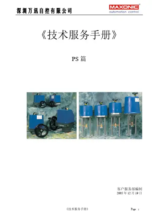
第一章
一、特点
1、一体化设计,位置变送器、伺服放大器内装,调校方便。
2、结构简单,体积小巧,重量轻,便于安装维护。
3、采用精密小间隙密封齿轮传动,传动效率高,噪声低,寿命长,稳定性高,无需加油。
X2:执行器电机连接端子,连线方式参考图1。
X3:控制信号输入与位置信号输出端子,该端子标有3、4号的为控制信号输入端子,标有5、6号的为位置信号输出端子,连线方式参考图1。
X5:执行器位置电位器接线端子,连接方式参考图1。在按图示连接方式连接时,应确保执行器的电位器与电机板上端子X0的连接关系如图2所示。
接线如下图:其中X5/1为电机的如下图:
公共端,X5/2为电机开方向的L1
端,X54为电机关方向的L2端。
四、独立位置变送器接线
第四章
一、 限位开关的调整
二、伺服放大板PSAP5调试说明书
1、安全事项
调试过程中不可触摸电路板上导体部分,以防触电。
确保各接线端子正确连接。
2、接线端子介绍
X1:电源端子。
PS+POT+PSMF2DC
开关(24V直流电源)动作模式,输出4--20mA反馈信号
调节型
PS+POT+MSC305+MSC308
调节动作模式,输入/出4--20mA反馈信号
PS+POT+PSAP4C
四、PS反馈齿轮的直径与行程
直径(mm)
H行程(mm)
10.8
H=25(塑料)
Panduit 10Gig SFP+ 直连铜线组装User Guideline说明书

10Gig™ SFP+ Direct Attach Copper Cable AssemblyInstallation Guidelines PN533BIntroductionAs virtualization, consolidation, and convergence initiatives continue to expand in Data Centers, so do the demands placed on the physical infrastructure. To meet the needs for higher bandwidth along with lower power interconnects, Panduit® offers 10Gig™ SFP+ Direct Attach Copper Cable Assemblies.This high speed data transport capability is ideal as server virtualization becomes more prevalent. 10Gig interconnects are needed to facilitate effective server utilization to run multiple virtual machines as well as server consolidation. By incorporating 10Gig™ SFP+ Copper Cable Assemblies into the physical infrastructure, organizations can achieve 10Gig performance without additional signal processing or conversion. This provides an ideal low power, low latency 10 Gbps server interconnect option for top of rack switching deployments.Passive 10Gig™ SFP+ Copper Cable Assemblies generally have a reach limitation of 7m (23 ft.), and many network deployments will consist of a mixed copper/fiber solution with Panduit 10Gig™ OM3 fiber. Panduit 10Gig™ SFP+ Direct Attach Copper Cable AssembliesPanduit 10Gig™ SFP+ Copper Cable Assemblies are factory terminated and constructed of high-speed twin-axial shielded cable with SFP+ modular connectors on each end. The cables are compliant to the SFF-8431 specification.The Small Form Factor committee approved and published SFF-8431 in July of 2009, with Panduit® as a member and a signee. The document covers host ports, optical transceivers, and copper cables. Appendix E specifies direct attach copper cable assemblies.These passive cable assemblies offer a low power, low latency, low cost option for a 10Gig interconnect. They may be plugged into SFF-8431 SFP+ compliant ports and are interchangeable with fiber optic transceivers. (Note: some system vendors have designed copper-only or fiber-only SFP+ ports, so be sure to confirm host port capabilities with the active equipment vendor)The Panduit® 10Gig™ SFP+ Direct Attach Cable Assemblies are constructed with high frequency 10 GHz 100 ohm parallel shielded pairs, with two wire pairs in the cable. Panduit® uses 30 AWG for cables less than 4m in length and uses 24 AWG for 4m and longer cables.The connector consists of a paddle card with patent pending circuitry to ensure superior high frequency signal integrity, is housed in a die cast backshell, and incorporates a latching mechanism that allows insertion and de-insertion into the mechanical cage of a host port on the active equipment. The same host port cage can accept optical transceivers or direct attach cable assemblies. The back of the paddle card has pads which form the contacts to the 20 pin host connector inside the cage. The connector has an EMI shroud that provides 360 degrees of contact with the host cage to ensure excellent EMI immunity.Cross-section 2-pair twin-axial cable Panduit® SFP+ connectorStandard Cable Part NumbersPart Number Length* Cable Gauge Nominal Cable O.D. Weight/pcPSF1PXA0.5M** 0.5m (1.6 ft.) 30 AWG 4.1mm (0.161 in.) 0.10 lb.PSF1PXA1M** 1.0m (1.6 ft.) 30 AWG 4.1mm (0.161 in.) 0.13 lb.PSF1PXA1.5M** 1.5m (4.9 ft.) 30 AWG 4.1mm (0.161 in.) 0.16 lb.PSF1PXA2M** 2.0m (6.6 ft.) 30 AWG 4.1mm (0.161 in.) 0.19 lb.PSF1PXA2.5M** 2.5m (8.2 ft.) 30 AWG 4.1mm (0.161 in.) 0.22 lb.PSF1PXA3M** 3.0m (9.8 ft.) 30 AWG 4.1mm (0.161 in.) 0.25 lb.PSF1PXA3.5M** 3.5m (11.5 ft.) 30 AWG 4.1mm (0.161 in.) 0.28 lb.PSF1PXD4M** 4.0m (13.1 ft.) 24 AWG 6.0mm (0.236 in.) 0.49 lb.PSF1PXD4.5M** 4.5m (14.4 ft.) 24 AWG 6.0mm (0.236 in.) 0.50 lb.PSF1PXD5M** 5.0m (16.4 ft.) 24 AWG 6.0mm (0.236 in.) 0.60 lb.PSF1PXD5.5M** 5.5m (17.6 ft.) 24 AWG 6.0mm (0.236 in.) 0.62 lb.PSF1PXD6M** 6.0m (19.7 ft.) 24 AWG 6.0mm (0.236 in.) 0.70 lb.PSF1PXD6.5M** 6.5m (20.8 ft.) 24 AWG 6.0mm (0.236 in.) 0.71 lb.PSF1PXD7M** 7.0m (23.0 ft.) 24 AWG 6.0mm (0.236 in.) 0.81 lb.*Panduit® 10Gig™ SFP+ copper cables have a length tolerance of + .15 - 0m** Add cable color code to end of part number, BU for Blue, WH for White, BL for Black.Cable Length Deployment NoteNote that the Panduit® 10Gig™ SFP+ Direct Attach Cable Assembly lengths are measured from cable connector tip- to-tip. However, much of the connector is inserted into the host port. Therefore one may wish to add approximately 47mm or 1.87 in. to each end or approximately 0.1m total to port-to-port length and cord routing calculations.Connector EEPROMPanduit® 10Gig™ SFP+ Direct Attach Copper Cable Assemblies are intelligent cables. The connector has an integrated EEPROM with information populated in registers that is provided to the active equipment when queried through an I2C bus Most active equipment port allow for interchangeable types of me to be plugged into its ports. The registers in the EEPROM provide a method for the connector to identify itself as an SFP+ passive copper module to allow the active equipment to operate in the proper mode. Other information contained in the memory registers includes vendor name (Panduit), part number, serial number, and cable length in meters.SFP+ Cable Assembly Connector Pin OutSFP+ Pin Assignment DefinitionsContactLogic(1)SymbolPower Sequence Order Description NoteCase Case Note 2 Module case2 1VeeT 1st Module transmitter ground 3 2 LVTTL-O Tx_fault 3rd Module transmitter fault (N/A) 4 3 LVTTL-I Tx_disable 3rd Transmitter disable (N/A)4 4 LVTTL-I/O SDA 3rd 2-wire serial interface data line, same as MOD-DEF25 5 LVTTL-I/O SCL3rd 2-wire serial interface clock, same as MOD-DEF15 6Mod_ABS 3rd Module absent, connected to VeeT or VeeR in module 6 7 LVTTL-I RSO 3rd Rate select 0, optionally controls SFP+ receiver (N/A) 4 8 LVTTL-O Rx_LOS 3rd Receiver loss of signal indication (N/A)4 9LVTTL-IRS13rdRate select 1, optionally controls SFP+ transmitter (N/A)410 VeeR 1st Module receiver ground 311 VeeR 1stModule receiver ground312 CML-O RD- 3rdReceiver inverted data output13 CML-O RD+ 3rdReceiver non-inverted data output14 VeeR 1stModule receiver ground315 VccR 2ndModule receiver 3.3V supply16 VccT 2ndModule transmitter 3.3V supply17 VeeT 1stModule transmitter ground318 CML-I TD+ 3rdTransmitter non-inverted data output19 CML-I TD- 3rdTransmitter inverted data output20 VeeT 1stModule Transmitter Ground3 Notes:1. Labeling as Input (I) and Output (O) are from perspective of the module (cable connector)2. The case makes electrical contact to the host cage before any board edge contacts are made3. The module signal grounds, VeeR and VeeT, should be isolated from the module case4. Tx-fault, Tx_disable, rate select, and loss of signal functions are not implemented in passive copper cable assemblies5. SDA and SCL are the data and clock pins for the I2C interface to the EEPROM on board the module. The registers are defined in SFF-8472.6. Mod_ABS is an output pin to indicate if the module is present in the host port It is connected to ground in the module (cable connector)Installing and Removing 10Gig™ SFP Copper Cable AssembliesTo attach a cable assembly, remove the purple protective EMI cap. Then simply insert the connector end into the cage of the SFP+ host port in the active equipment. Make sure the cable is fully inserted and engaged.ATTENTION: Observe precautions for handling electrostatic sensitive electronic devices when installing this product. Ensure that you are properly grounded with a wrist strap or equivalent while installing10Gig™ SFP+ Copper Cables.To disengage, gently pull the latch release and the cable assembly will easily disengage the port. The Panduit® 10Gig™ SFP+ Direct Attached Copper Cable Assemblies have been designed to fit into high-density belly-to-belly faceplates.Cable ManagementThe weight of large bundles of SFP+ twin-axial cables can exert a significant force along the horizontal plane, and specifically on the host port of the active equipment. If the cable emerges from the rear of the connector at too sharp an angle, excess mechanical stress may be transmitted both along the cable and into the circuit board located inside the connector. Excessive side forces exerted by the cable can also misalign the plug in the equipment-mounted receptacle. These forces may degrade performance or even possibly damage the connector and lead to failure. It is important to observe and maintain proper cable bend radius and equally important to provide adequate and secure strain relief on the cable.In order to help maintain proper bend, it is recommended to pre-form the strain relief bend on the cable before installing. The minimum recommended bend radius is 5X the cable outside diameter (O.D.) for a single time bend and 10X the OD for repeated bends.Cable Wire Gauge O.D. Min. Bend Radius (r)30 AWG 4.1mm (0.16 in.) 20.5mm (0.80 in.)24 AWG 5.6mm (0.22 in.) 28.0mm (1.10 in.)To help manage the weight of bundled cable and ensure they do not sag over time, a cable manager or strain relief bar should be installed to support SFP+ Copper Cable Assemblies and provide strain reliefalong the horizontal plane. Strain relief bars facilitate the correct alignment of cable and connector intothe port, and help installers observe manufacturer and bend radius requirements of cable close to the connector. The strain relief bars also help keep cables routed clear from spaces directly behind server and switch equipment, reducing thermal resistance through the equipment and promote effective cooling and airflow. To ensure long-term reliability, it is recommended to use a rack with integral cable management features such as the Panduit® Net-Access™ Cabinets.Tak-Ty™ Hook and Loop Cable Ties should be used to bundle the cables together and tie them to the strain relief bars and cable managers. This should be done carefully to ensure the cables are firmly in place and will not move, but not so tight as to deform or stress the cable jacketing.Cable Installation Tips and Best PracticesThere are a few practical steps that can be taken during installation to optimize the effectiveness of the layout.▪For overhead cable routing, place the switches near the top of the racks▪For under floor cable routing, place the switches near the bottom of the racks▪Do not route SFP+ Cable Assemblies parallel to power cables, they should only cross at right angles▪Do not route cables in front of fans or air ventilation areas of the rack▪Do not kink cables▪Do not twist connectors▪Use Tak-Ty™ Hook and Loop Cable Ties to secure cables, do not use plastic cable tiesSlack ManagementStandard cables come in 1m (3.3 ft.) increments. Often installers will standardize on a small number of standard lengths to simplify the bill of material. One cannot always anticipate possible infrastructure obstacles on site so it is good practice to estimate long when defining cable lengths. Therefore, it is possible that there will be cable slack and this needs to be managed properly to ensure reliable long term performance. The slack in the cable should be shaped and looped so as not to violate bend radius. Slack or loops should be securely tied in place so they do not slip or sag over time.General Deployment Topology GuidelinesWithin a single 84 in. 45 RU cabinet, conservatively the longest connection will be 7 ft. or 2.1m to reach from the top U to the bottom and approximately 1.5 ft. or 0.45m to route to any port on either end. A 3m cable should be adequate to connect any two ports within a cabinet.84 inches =7 ft. = 2.1m Example cabinet with 2 top of rack switches (ToR) and 20 2U servers with Dual SFP+ NICs total of 40 SFP+ cables Conservatively, longest cable required to reach farthest port is 2.1 + 2.x 0.45 ≈ 3mExample of 3 cabinet Pod with 40 2 RU servers distributed over 3 cabinets with 2 ToR switches in center cabinet requires 80 SFP+ cables with longest cable of 4m Example of 5 cabinet Pod with 80 2 RU servers distributed over 5 cabinets with 4 ToR switches in center cabinet requires 160 SFP+ cables with longest cable of 5m10Gig™ SFP+ Copper Cable Assembly Installation Guidelines PN533BFor Instructions in Local Languagesand Technical Support: /resources/install_maintain.aspE-mail:***********************Phone:866-405-6654Using Middle of Row switching topology, an 8 cabinet row may be achieved with 7m cables. This has two switchcabinets in the center and 3 server cabinets on each side. If all switching were placed in a single center cabinet, a 9 cabinet row with 8 server cabinets may be covered. To enable longer row, fiber and SFP+ optical transceivers arerequired. A hybrid solution of Panduit ®10Gig™ SFP+copper for the inner cabinets and Panduit ®10Gig™ OM3 fiber to the outer cabinets will be the cost effective solution.。
电子课件-《Photoshop平面设计与制作》-A06-4050项目十 通道的应用、图像批处理及 GIF 动画的制作

任务 3 小狗和树
2. 魔棒抠图法
(1)适用范围:图像和背景色色差明显。 (2)思路:通过选择并删除背景色来获取图像。 (3)缺点:不适用于颜色及形状复杂的图像。
3. 色彩范围抠图法
(1)适用范围:图像和背景色色差明显,背景色单一。 (2)思路:通过选择并删除背景色来获取图像。 (3)缺点:不适用于带有复杂背景色的图像。
任务 5 图片水印
三、“动作”面板
1. 可将一系列命令组合为单个动作, 从而使执行任务自动化。
2. 可同时处理批量的图片。 3. 使用“动作”面板可以记录、播 放、编辑和删除个别动作,也可以用 来存储和载入文件。
“动作”面板
LOGO
任务6 流汗的小狮子
36
任务 6 流汗的小狮子
1. 了解 Photoshop 中的动画。 2. 了解动画的原理。 3. 能制作 GIF 动画。
任务 1 含苞待放
很多图片都有这种效果:在一片单调的怀旧色中突然有一抹彩色存在, 非常亮眼而且突出主题。本任务利用颜色模式的转换,用通道将图所示图像 的颜色进行调整,实现这种效果,如图所示。
素材
最终效果
任务 1 含苞待放
一、颜色模式和通道的概念
颜色模式是将某种颜色表现为数字形式的模型,或者说是一种记录图像颜 色的方式。不同的颜色模式通过不同基本元素的各种组合对颜色进行记录。
任务 1 含苞待放
三、通道
1. 颜色通道
颜色通道,就是将构成图像的全部颜色信息整理并表现为单色图像的工具。 每个图像都有一个或多个颜色通道,图像中默认的颜色通道数取决于其颜 色模式,即一个图像的颜色模式将决定其颜色通道的数量。在默认情况下, CMYK 图像有 4 个通道;RGB 和 Lab 图像有 3 个通道;位图模式、灰度、 双色调和索引颜色图像只有 1 个通道。
SP CP SSP技术服务教材

第一节 泵的安装泵的安装的好坏对泵的运行和寿命有重要影响,安装前应仔细阅读泵安装使用说明书有关内容;安装必须按要求仔细进行。
(一)安装要求:一、安装前应确认入口大小是否适当。
二、 应预留电缆出口,方便配线作业;泵安装完成后电缆须适当固定之。
三、 泵入水口至池壁的距离至少50cm以上。
四、 出水管路的重量不能完全作用在泵上,出水管路必须有适当的支撑与固定。
五、 泵安装前,应先检查电压与频率,是否与铭牌标示相符。
六、 请勿任意更换电缆长度,请勿将电缆接头置入水中。
七、 电缆线与链条须分别固定,避免起吊泵时拉扯造成电缆损坏。
八、 必须装水位控制浮球开关,使泵自动操作;保证池水高度不低于水位警戒线。
九、 为使泵运转稳定,浮球装置位置不要靠近池水入口处。
(二)泵的安装(参见图A-图D)一、 确定固定架及固定板的位置在排水管道一侧的池口壁上刻好竖线标记,使得竖线在排水管中心的平面内,依该竖线作为固定架及固定板的安装对称基准。
二、 安装固定架及固定板首先使固定架及固定板的中心线与池口安装基准竖线重合,按其槽距在池口壁钻出膨胀螺钉底孔,插入膨胀螺钉将固定支撑紧固,此刻无需完全拧紧。
对口径50、80、100三种口径的着脱用固定架及固定板,应先将固定板用膨胀螺栓固定于池口壁,然后将固定架安装于固定板上。
三、 安装着脱本体a、把着脱本体放置池底,从固定架上挂一根垂线,并与固定架的中心线重合,根据垂线找正着脱本体的中心线,注意使固定架上的两个圆锥中心和着脱本体上的两个圆锥中心在同一轴上,调整好地脚螺栓的胀锚孔或预留孔的位置。
b、浇筑预留孔,用混凝土浇埋,应保证地脚螺栓的安装位置符合安装图的要求。
四、 安装导管若污水池深小于6m,则根据池深与底座和固定支撑两圆锥体之间的距离,锯好两根导管的长度,分别套入锥体内,并应使导管垂直。
若污水池深大于6m,则应用联管器将长导管和短导管联接起来,并用止动紧定螺钉紧固,以上述方法安装即可。
pssh安装使用

pssh安装使用目录PSSH安装使用 (1)1PSSH简介 (3)2安装环境 (3)2.1测试服务器描述 (3)3安装PSSH(三台机器都要安装) (3)4配置私钥 (4)5PSSH使用: (6)5.1穿件SERVET.TXT把服务器IP加入 (6)EG: (6)1)执行命令 (6)1 pssh简介在日常工作中,批量管理服务器是个力气活,如果人工一台一台处理,效率低下。
此时,老外写的pssh工具实现了批量管理。
它的原理是先建立ssh私钥认证,然后用pssh工具批量管理。
2 安装环境2.1测试服务器描述1.三台vmware虚拟机,内存均为256M。
2.操作系统: rhel5.53. IP规划p ssh.zi p3 安装pssh(控制机安装)4 配置私钥1) 使用下列脚本批量生成:2) 控制机生产公钥:[root@Proxy opt]# ssh-keygen -t rsaGenerating public/private rsa key pair.Enter file in which to save the key (/root/.ssh/id_rsa):Enter passphrase (empty for no passphrase):Enter same passphrase again:Your identification has been saved in /root/.ssh/id_rsa.Your public key has been saved in /root/.ssh/id_rsa.pub.The key fingerprint is:ef:fb:92:14:0e:f1:37:b1:4c:4a:b2:76:47:55:6b:51 root@Proxy3) 使用下列脚本生成等效性文件:batch_sshkey.sh#!/bin/bashcd /rootcat /root/.ssh/id_rsa.pub > /root/.ssh/authorized_keysfor i in `cat /opt/ip.txt`doip=$(echo "$i"|cut -f1 -d":")password=$(echo "$i"|cut -f2 -d":")expect -c "spawn scp /root/.ssh/authorized_keys /root/remote_operate.sh root@$ip:/tmp/ expect {\"*yes/no*\" {send \"yes\r\"; exp_continue}\"*password*\" {send \"$password\r\"; exp_continue}\"*Password*\" {send \"$password\r\";}}"expect -c "spawn ssh root@$ip "/tmp/remote_operate.sh"expect {\"*yes/no*\" {send \"yes\r\"; exp_continue}\"*password*\" {send \"$password\r\"; exp_continue}\"*Password*\" {send \"$password\r\";}}"Done[root@Proxy opt]# vi ip.txt (前面ip,后面密码:作为分隔)192.168.88.130:xgllpass192.168.88.131:xgllpass4) remote_operate.sh(此脚本放root目录下)#!/bin/bashif [ ! -d /root/.ssh ];thenmkdir /root/.sshficp /tmp/authorized_keys /root/.ssh/5 pssh使用:5.1 穿件servet.txt把服务器IP加入[root@Proxy opt]# more server.txt192.168.88.130192.168.88.131eg:1) 执行命令[root@Proxy opt]# pssh -h /opt/server.txt -l root -P uptime192.168.88.130: 20:59:47 up 14:40, 2 users, load average: 0.00, 0.00, 0.00192.168.88.130: [1] 22:13:26 [SUCCESS] 192.168.88.130 22192.168.88.131: 20:59:42 up 14:34, 2 users, load average: 0.00, 0.00, 0.00192.168.88.131: 192.168.88.131: [2] 22:14:07 [SUCCESS] 192.168.88.131 22pssh -h ip -i "touch /tmp/1.txt"-P是输出来了就直接print出来,不论顺序的。
PS执行器按装调试和维护手册-PPT精选文档
PSQ按装
2.3 球型铰链尺寸:
2.4 按装空间及环境要求:
PSQ按装
2.5、PSQ角行程执行机构外型尺寸(PSQ1002尺寸同PSQ502)
电子式电动执行机构PS-MA (调试) PS-MA执行机构机械限位 :行程限位开关的调整
行程限位说明:(1) PS-MA电子式通过设置机械行程开关实现; (2) PS-AMT智能型通过软件参数设置实现,其机械行程开关已经调到最大行程;
PS-MA执行机构调试
• PS-MA调节模式调试步骤:
PS-MA调试
在标准型号的基础上增加PS伺服放大器,即可实现执行机构的调节动作,执行机构的调试也就是 对PS伺服放大器的调试。在您根据阀门的行程调整好执行器的开关限位之后,即可通电调试, 具体方法如下:(PS伺服放大器前期型号是PSAP4,后改进为PSAP5,互相通用)
注意:盘簧的安装一定要如图中所示两片扣在一起,一对一对的安装!
PS按装
1.1 PSL直行程执行器与阀门连接 PSL执行机构通过支架连杆、T型连接件与阀门连接,首先需要阀杆与执行机构输出轴必须完全缩回。 警告:此时只能用手轮操作执行机构出轴 ★执行器连杆插入阀门安装法兰孔,上紧连杆螺母
★根据阀门情况放置盘簧垫片
(一)、PSAP5的调试说明和方法
SW2: 正反作用开关 SW3: 调试用开关(正反作用开关) ZERO:反馈零点电位器 SPAN:反馈满度电位器 P1: 死区(灵敏度)调整电位器 P2: 滞环(回差)调整电位器 LED1: 关动作指示灯 LED2:开动作指示灯 LED3:工作指示灯
1、接线端子介绍
(三)、PSQ/PSR-MA行程限位 1、行程关限位:执行器安装好后,手动使阀门到全关位置。用小平口 螺丝刀逆时针旋转凸轮K1,直到关限位开关动作。去掉橡胶帽3,旋松 螺母M1,顺时针旋转螺钉N1半圈,再备紧螺母M1,见左图。 2、行程开限位:手动使阀门到全开位置,用小平口螺丝刀顺时针旋转 凸轮K2,直到开限位开关动作。去掉橡胶帽3,旋松螺母M2,顺时针旋 转螺钉N2半圈,再备紧螺母M2,见左图。 注意:一般情况下不要调整力矩开关
PHS使用说明书
小灵通干放使用说明东方信联科技有限公司1. 适用范围我公司生产的小灵通干放适用于1900~1920MHz,1900~1915MHz,1900~1910MHz,1893~1910MHz四个频段(分别用A、B、C、D四个字母表示),输出功率为27 dBm 、30 dBm、33 dBm三种类型。
本说明书设计依据:2005年11月《PHS网络室内覆盖系统技术规范》(试行)和2005年8月《云南电信室内电线综合覆盖系统技术规范》(试行)。
2. 主要技术指标2.1工作频率:1893MHz~1920MHz之内频段可选2.2工作带宽:20MHz、17MHz、15MHz、10MHz可选2.3每载波占用带宽:≤288KHz2.4增益:上、下行增益30dB;DGC调节范围:20dB,增益调节步长:1dB;AGC:控制范围20dB.2.5标称功率:按载波数量和每载波输出功率定义干放种类,如下表所示。
以平均每载波输出功率进行链路预算。
2.6输入/输出功率:下行最大输入功率:+10dBm,下行最小输入功率:-2dBm;下行最大输出功率:≤33dBm;上行最大输出功率:≤-10dBm。
2.7噪声系数: < 4dB(上行)2.8矢量幅度误差(EVM)指标要求:RMS矢量误差:≤5%峰值矢量误差:≤10%2.9带内平坦度:≤1dB2.10驻波比:≤1.52.11带内互调衰减:在2载波和4载波标称输出功率下,均满足:≤-45dBc(1dB压缩点);2.12上下行滤波器带外抑制:≥45dBc (偏离工作频带≥±10MHz ) 2.13带外杂散:≤-60dBm/3.84MHz (1920-1980MHz )或≤-71dBm/300kHz (1920-1980MHz ); ≤-60dBm/100kHz (1710-1850MHz ); ≤-36dBm/30KHz(9KHz ~1GHz); ≤-30dBm/30KHz(1GHz ~12.75GHz)。
PS中通道混合器的作用及使用简说
PS中通道混合器的作用及使用简说先说一下通道亮度与颜色变化的关系:一般规律:在RGB颜色模式中,通道红——越亮,画面就越红(减绿);越暗就越绿(减红);通道绿——越亮,画面就越绿(减品);越暗就越品(减绿);通道蓝——越亮,画面就越蓝(减黄);越暗就越黄(减蓝);现在建一个大小合适的文档,填充中性灰颜色(H=0、S=0%、B=50%或R=G=B=128或#808080等)。
通道混和器的图层。
加全白蒙版,通道混和器就作用于整个某通道;加局部透明蒙版,通道混和器就只作用于某通道的局部透明区域。
在RGB颜色模式下,输出通道只有红(Alt+3)、绿(Alt+4)、蓝(Alt+5)。
在CMYK颜色模式下,输出通道只有青色(Alt+3)、洋红(Alt+4)、黄色(Alt+5)、黑色(Alt+6)。
通道混和器的面板中,红色百分比、绿色百分比、蓝色百分比是指原图通道相对应的通道红、通道绿、通道蓝参与计算的百分比。
比如,在修复通道时,往往是某个通道噪点太多,品质不高;相反,另一个通道的品质很好,色阶丰富、平滑、细腻。
这时,我们就会让品质好的通道,占更多的百分比参与计算,从而得到一个较好的新通道,将原来品质差的通道替换掉。
选择输出通道红(Alt+3),这时面板参数计算得到的新通道就将替换原来的通道红;选择输出通道绿(Alt+4),这时面板参数计算得到的新通道就将替换原来的通道绿;选择输出通道蓝(Alt+5),这时面板参数计算得到的新通道就将替换原来的通道蓝;······规律1:如果通道混和器中,对某通道始终有等式成立:红色百分比%+绿色百分比%+蓝色百分比%=总计100%那么,该通道的中性灰的颜色就会保持不变。
见图2图2在人像调色中,人的肤色往往都比较接近中性灰,所以,就可以用这个办法,先大大改变背景和人物衣服的颜色,而人的肤色改变就很少。
在水墨画效果的调色中,也可以用这个办法,保证中性灰的颜色不变,而改变整个画面的色调等。
管道混合器安装要求
管道混合器安装要求
管道混合器的安装要求主要包括以下几个方面:
1. 安装位置:混合器应安装在管道上,位置要方便操作和维护。
同时,需要保证管道上游有足够的直管段作为混合室,以保证混合效果。
2. 安装方向:混合器外壳上通常有进口和出口标识,需要按照标识正确安装,确保介质可以顺利流经。
3. 安装支承:混合器需要通过支架或法兰连接来固定在管道上,以保证其稳定性和安全性。
4. 安装前准备:在安装之前,需要对管道进行清洗和除杂处理,确保管道内部没有杂质或污垢,以免影响混合效果。
同时,也要检查管道的尺寸和材质是否符合混合器的要求。
5. 密封:混合器的连接部分需要进行密封处理,以防止漏液或逆流现象的发生。
常用的密封材料有橡胶垫圈、填料和密封胶等。
6. 排气:在安装完成后,需要对混合器进行排气处理,以确保管道内没有气体阻塞。
7. 调试:安装完成后,需要进行调试和测试,确保混合器的工作效果和参数符合设计要求。
调试过程中需要注意安全,防止介质泄漏或喷射。
总之,管道混合器的安装要求主要是为了保证其正常运行和混合效果,需要按照标准和规范进行安装,并进行相应的测试和调试工作。