
MAX调试手册
为 ∞ Ω) 所有厅门关上时
为 ON 正常为 OFF
GR/F212
广州广日电梯 工业有限公司
GreenMax 系统电梯调试手册 (电气部分)
编 号:SJG 05-008 共 28 页 第 5页
第三章:慢车、快车调试说明
一、现场调试准备 1、首先检查是否具备调试条件: 1.1、用户有否按要求将电源提供到机房(正常或临时);
1.2、主机加油量是否合适,型号是否正确;
750
1400
30
200
(mm) 1.75m/s
750
1800
2m/s
750
2200
二、上、下平层感应器、门区感应器的位置
1、在 GreenMax 控制系统中,电梯的平层控制需要现场安装门区感应器和若干块隔磁板。有
关感应器和隔磁板的具体要求见表:
类别
平层感应器
隔磁板
类型、材质
永磁感应器(YG-3C)
限位开关(SWK、XWK)、上、下单层强慢开关(SHK、XHK)各一个外,还要求井道安装上下对应的
上、下多层强迫慢车开关(SHK1、XHK1)。
井道中的具体位置见下表。
开关(Switches) XHK(SHK) XHK1(SHK1) XWK(SWK)
XZK(SZK)
1.00m/s
750
距离 1.50m/s
1.3、底坑缓冲器安装完成否;
1.4、各层厅门、门锁是否安装完毕; 1.5、电梯接线是否已全部完成; 1.6、井道线槽是否已上好盖; 1.7、井道引线的金属软管是否固定良好; 1.8、各层厅门门套是否已塞好; 1.9、井道有否妨碍轿厢、对重架运行的物体;
2、电气接线检查
2.1、机房电气接线检查
序号 检查的回路
第二章:井道开关及上、下平层感应器的位置
一、井道开关的位置 在 GreenMax 系统中,要求井道中安装的开关有两种情形 1、若梯速不超过 1m/s 时,要求井道中安装上下对应的上、下极限开关(SZK、XZK)、上、下
限位开关(SWK、XWK)、上、下单层强慢开关(SHK、XHK)各一个;
2、若梯速超过 1m/s 时,除要求井道中安装上下对应的上、下极限开关(SZK、XZK)、上、下
2、当 GreenMax 控制系统增加微动平层功能时,需按下图安装隔磁板和感应器,在平层位置 时,MQG、MQ1、MQ2 均插入在隔磁板的正中间。
隔磁板安装 位置示意图
采用接驳件 时的情况
感应器安装 位置示意图 SQG
MQG
XQG
注:SQG、MQG、XQG 感应器型号为 YG-3C(感应器插入隔磁板后是常开状态),MQ1、MQ2 感应 器型号为 YG-3H(感应器插入隔磁板后是常闭状态)。
GR/F212
广州广日电梯 工业有限公司
GreenMax 系统电梯调试手册 (电气部分)
编 号:SJG 05-008 共 28 页 第 3页
第一章:键盘操作说明
GreenMax 系统可以通过控制板上的 LED+按键的键盘部分及操纵面板部分对控制系统进行参 数设定、状态监视、控制驱动器的运行/停止等操作。其键盘操作方法与 GRE01 系统相同,具体操 作方法请参考资料《SJK04-010》
铁板厚度≥1.5mm
高度、长度、深度 门区感应器安装在隔磁板的正 隔磁板的长度为 250,插入深度
GR/F212
广州广日电梯 工业有限公司
安装位置 数量
GreenMax 系统电梯调试手册 (电气部分)
中间
轿顶 1 个/台
编 号:SJG 05-008
共 28 页 第 4页 超过 3/4。
井道 1 块/层
目录
一、键盘操作说明······························第 2 页 二、井道开关及上、下平层感应器的位置··········第 2 页 三、慢车、快车调试说明························第 4 页 四、变频器参数································第 21 页 五、PI 值调整说明·····························第 26 页 六、故障代码表································第 27 页 七、改进意见表································附 页
FL2-11、FL2-12 FL2-24~低压变电箱侧接线端子 FL2-25~低压变电箱侧接线端子 FL2-22~低压变电箱侧接线端子 FL2-23~低压变电箱侧接线端子
FL1-24、FL2-11
12
抱闸线圈
FL2-9、F2-10
测试标准 正常为 ON 正常为 ON 正常为 ON
方法
打板未打到开关 时开关状态为 ON
SHK F11 插接器-5、F11 插接器-6
上
强迫减速 6
SHK1 F11 插接器-7、F11 插接器-8
开关
XHK F12 插接器-5、F12 插接器-6
下
XHK1 F12 插接器-7、F12 插接器-8
7
厅门开关
FL1-11、FL1-12
8
消防开关
9 AC220V 输入
10 AC36V 输入 11 抱闸反馈开关
编 号:SJG 05-008 版本号:01
GreeenMax 系统电梯调试手册 (电气部分)
更改文件号
GR/F211
签字
日期
更改文件号
签字
日期
广州广日电梯 工业有限公司
GreenMax 系统电梯调试手册 (电气部分)
编制
校对
标准化
审定
批准
编 号:SJG 05-008 共 28 页 第 1页
广州广日电梯工业有限公司 2005 年 12 月
测试点
1 盘车手轮开关
FL1-7、FL1-8
2
底坑急停
F15 插接器-5、F15 插接器-6
3 限速器开关
FL1-3、FL1-4
上 4 限位开关
下
F11 插接器-3、F11 插接器-4 F12 插接器-3、F12 插接器-4
上 5 极限开关
下
F11 插接器-1、F11 插接器-2 F12 插接器-1、F12 插接器-2
GR/F212
广州广日电梯 工业有限公司
GreenMax 系统电梯调试手册 (电气部分)
编 号:SJG 05-008 共 28 页 第 2页
说明: 本调试手册所列的全部内容仅适用于 GreenMax 系统电梯(GreenMax 系统适用于以无齿同步电机为拖动系统的梯种)控制系统调试使用,不 作其它控制系统调试使用。
MAX1658 MAX1659线性调节电源说明说明书
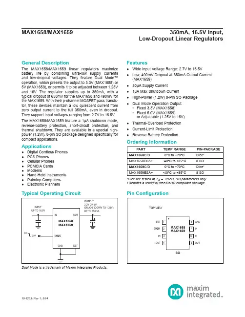
General DescriptionThe MAX1658/MAX1659 linear regulators maximize battery life by combining ultra-low supply currents and low-dropout voltages. They feature Dual Mode™ operation, which presets the output to 3.3V (MAX1658) or 5V (MAX1659), or permits it to be adjusted between 1.25V and 16V. The regulator supplies up to 350mA, with a typical dropout of 650mV for the MAX1658 and 490mV for the MAX1659. With their p-channel MOSFET pass transis-tor, these devices maintain a low quiescent current from zero output current to the full 350mA, even in dropout. They support input voltages ranging from 2.7V to 16.5V.The MAX1658/MAX1659 feature a 1μA shutdown mode, reverse-battery protection, short-circuit protection, and thermal shutdown. They are available in a special high-power (1.2W), 8-pin SO package designed specifically for compact applications.Applications●Digital Cordless Phones ●PCS Phones ●Cellular Phones ●PCMCIA Cards ●Modems●Hand-Held Instruments ●Palmtop Computers●Electronic PlannersFeatures●Wide Input Voltage Range: 2.7V to 16.5V ●Low, 490mV Dropout at 350mA Output Current(MAX1659) ●30μA Supply Current ●1μA Max Shutdown Current●High-Power (1.2W) 8-Pin SO Package ●Dual Mode Operation Output:• Fixed 3.3V (MAX1658) • Fixed 5.0V (MAX1659)or Adjustable (1.25V to 16V) ●Thermal-Overload Protection ●Current-Limit Protection ●Reverse-Battery ProtectionDual Mode is a trademark of Maxim Integrated Products.19-1263; Rev 1; 5/14*Dice are tested at T A = +25°C, DC parameters only.+Denotes a lead(Pb)-free/RoHS-compliant package.PART TEMP RANGE PIN-PACKAGE MAX1658C/D 0°C to +70°C Dice*MAX1658ESA+-40°C to +85°C 8 SO MAX1659C/D 0°C to +70°C Dice*MAX1659ESA+-40°C to +85°C8 SOLow-Dropout Linear RegulatorsTypical Operating CircuitPin ConfigurationOrdering InformationIN to GND ...............................................................-17V to +17V Continuous Output Current ..............................................500mA Output Short-Circuit Duration ...........................................Infinite SET, SHDN to GND ...............................................-17V to +17V OUT to GND ..............................................-0.3V to (VIN + 0.3V)Continuous Power Dissipation (Note 1)SO (derate 14.5mW/°C above +70°C) ............................1.2W Operating Temperature RangeMAX1658ESA/MAX1659ESA .........................-40°C to +85°C Junction Temperature ......................................................+150°C Storage Temperature Range ............................-65°C to +160°C Lead Temperature Range (soldering, 10sec) ..................+300°C(V IN = 5V (MAX1658), V IN = 6V (MAX1659); C OUT = 10μF; SHDN = IN; T A = T MIN to T MAX ; unless otherwise noted. Typical values are at T A = +25°C.) (Note 2)Note 1: See Operating Region and Power Dissipation section.PARAMETERSYMBOL CONDITIONSMIN TYPMAX UNITS Input Voltage RangeV INSET = OUT2.716.5VOutput VoltageV OUTSET = GND,0mA < ILOAD < 350mAMAX1658,5V ≤ V IN ≤ 16.5V 3.20 3.30 3.40VMAX1659,6V ≤ V IN ≤ 16.5V4.855.00 5.15Regulated Output Voltage Range (Note 3)1.2516V Maximum Output Current I OUT(MAX)350mA Current Limit I LIM 900mA Supply CurrentI Q3060μA Dropout Voltage (Note 4)ΔV DOI OUT = 1mA2mVI OUT = 350mAMAX16586501500MAX1659490875Line Regulation ΔV LNR MAX1658, V IN = 5V to 16.5V 0.03%/V MAX1659, V IN = 6V to 16.5V 0.05Load Regulation ΔV LDR I OUT = 0mA to 350mA0.003%/mA Startup Overshoot V OSH 0%V OUT Output Noise e n10Hz to 100kHz2.5mV P-P SHUTDOWN Logic-Low InputV INL SHDN 2.7V ≤ V IN ≤ 16.5V 0.4V Logic-High Input Threshold V INH SHDN 2.7V ≤ V IN ≤ 16.5V 2.0V Shutdown Input Bias Current I SHDN SHDN = GND or SHDN = IN 0.1μA Shutdown Supply Current I Q SHDN SHDN ≤ 0.4V 0.11μA Shutdown Exit Timet STARTV OUT = 5.0V120μs Low-Dropout Linear RegulatorsAbsolute Maximum RatingsStresses beyond those listed under “Absolute Maximum Ratings” may cause permanent damage to the device. These are stress ratings only, and functional operation of the device at these or any other conditions beyond those indicated in the operational sections of the specifications is not implied. Exposure to absolute maximum rating conditions for extended periods may affect device reliability.Electrical Characteristics(V IN = 5V (MAX1658), V IN = 6V (MAX1659); C OUT = 10μF; SHDN = IN; T A = T MIN to T MAX ; unless otherwise noted. Typical values are at T A = +25°C.) (Note 2)Note 2: Specifications to -40°C are guaranteed by design, not production tested.Note 3: Adjustable configuration only. V IN = 16.5V.Note 4: The dropout voltage is defined as (V IN - V OUT ) when V OUT is 100mV below the value of V OUT for V IN = V OUT + 2V.(V IN = 5V (MAX1658), V IN = 6V (MAX1659); SHDN = IN; SET = GND; C IN = 0.1μF; C OUT = 10μF tantalum; T A = +25°C; unless otherwise noted.)PARAMETERSYMBOLCONDITIONSMINTYPMAXUNITSSET INPUTSET Reference Voltage V SET I OUT = 10μA (Note 3) 1.1741.210 1.246V SET Input Leakage Current I SETT A = +25°C (Note 3)0.010.025μAT A = +85°C (Note 3)0.1THERMAL PROTECTION Thermal Shutdown Temperature T SD 165°C Thermal Shutdown HysteresisΔT SD10°C-8-7210100010k100100kMAX1659 POWER-SUPPLYREJECTION RATIO vs. FREQUENCY-56-64FREQUENCY (Hz)P S S R (d B )-48-32-40-24-16-10-9010100010k100100kMAX1658POWER-SUPPLYREJECTION RATIO vs. FREQUENCY-70-80FREQUENCY (Hz)P S R R (d B )-60-40-50-30-20Low-Dropout Linear RegulatorsElectrical Characteristics (continued)Typical Operating Characteristics(V IN = 5V (MAX1658), V IN = 6V (MAX1659); SHDN = IN; SET = GND; C IN = 0.1μF; C OUT = 10μF tantalum; T A = +25°C; unless otherwise noted.)0204060800369151218MAX1658SUPPLY CURRENT vs. INPUT VOLTAGEINPUT VOLTAGE (V)S U P P L Y C U R R E N T (µA )040801002060120140010020030040050150250350QUIESCENT CURRENT vs. LOAD CURRENTM A X 1658/59 t o c 09LOAD CURRENT (mA)Q U I E S C E N T C U R R E N T (µA )05001000150020003691215DROPOUT VOLTAGE vs. OUTPUT VOLTAGEOUTPUT VOLTAGE (V)D R O P O U T V O L T A GE (m V )200400600100300500700800100200300400DROPOUT VOLTAGE vs. LOAD CURRENTLOAD CURRENT (mA)D R O P O U T V O L T A GE (m V )BA100µs/divMAX1658LINE-TRANSIENT RESPONSEA: INPUT VOLTAGE (1V/div), V IN = 6V (HIGH), V IN = 5V (LOW)B: OUTPUT VOLTAGE (100mV/div)BAMAX1659LINE-TRANSIENT RESPONSEA: INPUT VOLTAGE (1V/div), V IN = 7V (HIGH), V IN = 6V (LOW)B: OUTPUT VOLTAGE (100mV/div)100µs/divV OUT = 5.0V0.9900.9940.9920.9960.9981.0000100200300400NORMALIZED OUTPUT VOLTAGEvs. LOAD CURRENTOUTPUT CURRENT (mA)O U T P U T V O L T A G E V N O M I N A L /V O U T (V )BA V OUT = 3.3VMAX1658LOAD-TRANSIENT RESPONSEMAX1658/59 toc13A: OUTPUT VOLTAGE (100mV/div)B: I OUT = 300mA (HIGH), I OUT = 40mA (LOW)200µs/divBAV OUT = 5VMAX1659LOAD-TRANSIENT RESPONSEMAX1658/59 toc12A: OUTPUT VOLTAGE (100mV/div)B: I OUT = 300mA (HIGH), I OUT = 40mA (LOW)200µs/divLow-Dropout Linear RegulatorsTypical Operating Characteristics (continued)(V IN = 5V (MAX1658), V IN = 6V (MAX1659); SHDN = IN; SET = GND; C IN = 0.1μF; C OUT = 10μF tantalum; T A = +25°C; unless otherwise noted.)PIN NAME FUNCTION1SET Output-Voltage Input. Connecting SET to ground selects the factory-preset 3.3V (MAX1658) or 5V (MAX1659) output voltage. For an adjustable output voltage, connect SET to a resistive voltage-divider from OUT to GND.2SHDN Shutdown Input. When SHDN is low, the device turns off and typically draws 0.1μA of supply current.3, 6, 7INUnregulated Input Supply Voltage, 2.7V to 16.5V input range. The IN pins also serve as heatsinks. Connect to a copper plane to achieve maximum thermal dissipation.4, 5OUT Regulated Output Voltage. Fixed or adjustable from 1.25V to 16V. Sources up to 350mA. For stable operation, bypass with a 10μF, low-ESR (<0.2Ω) capacitor from OUT to GND. For improved load-transient response, use a larger low-ESR capacitor.8GNDGroundBA0V3.3V100µs/divMAX1658 OVERSHOOT AND TIME EXITING SHUTDOWNMAX1658/59 toc14A: OUTPUT VOLTAGE (1V/div)B: SHDNPIN VOLTAGE (2V/div)BA0V5V100µs/divMAX1659 OVERSHOOT AND TIME EXITING SHUTDOWNMAX1658/59TOC15A: OUTPUT VOLTAGE (2V/div)B: SHDN PIN VOLTAGE (2V/div)10ms/div10Hz TO 100kHz NOISE, V OUT = 5V (1mV/div), I OUT = 165mAOUTPUT NOISE104103102101050kOUTPUT NOISE DENSITYvs. FREQUENCYFREQUENCY (Hz)O U T P U T N O I S E D E N S I T Y (n V R M S /√H z )Low-Dropout Linear RegulatorsTypical Operating Characteristics (continued)Pin DescriptionDetailed DescriptionThe MAX1658/MAX1659 are micropower, low-dropout linear regulators featuring Dual Mode operation, which allows them to deliver an adjustable (1.25V to 16.5V) or preset (3.3V for the MAX1658, 5V for MAX1659) output. They supply up to 350mA while requiring only 120μA of supply current (typically 30μA with no load). The devices include thermal-shutdown circuitry, output current limiting, a p-channel pass transistor, a Dual Mode compar-ator, and a feedback voltage-divider. Figure 1 shows the functional diagram.The 1.21V reference is connected to the amplifier’s inverting input. The error amplifier compares this reference with the selected feedback voltage and ampli-fies the difference. The error signal applies the drive to the p-channel pass transistor. If the feedback voltage is lower than the reference voltage, the transistor’s gate is pulled lower, increasing output current.The output voltage is fed back through an internal resistor network or an external user-selected network. The Dual Mode comparator examines the voltage at the SET pin and selects either the internal or external feedback path. If SET is below 65mV, internal feedback sets the MAX1658’s output voltage to 3.3V and the MAX1659’s to 5V. Otherwise, external feedback is used for an adjustable output between 1.25V and 16.5V. Additional features include internal current limiting, reverse-battery protection, thermal-overload protection, and a 1μA shutdown mode.Figure 1. Functional DiagramLow-Dropout Linear RegulatorsP-Channel Pass TransistorThe MAX1658/MAX1659 feature an internal p-channel MOSFET pass transistor. Using a MOSFET provides several advantages over similar pnp designs, including lower dropout voltage and extended battery life. Unlike bipolar transistors, MOSFETs reduce quiescent current, because they require no base current, particularly at heavy loads and in dropout. As a result, the MAX1658/MAX1659 operate at a low quiescent current even in dropout.Output-Voltage SelectionDual Mode operation allows the MAX1658/MAX1659 to operate at either a preset or a user-adjustable output voltage. The device compares the SET pin voltage with an internal 65mV reference. If the voltage is lower than 65mV (typically achieved by grounding SET), the device switches to an internal resistor-divider feedback network that sets the output voltage. The MAX1658’s preset output voltage is 3.3V and the MAX1659’s is 5V (Figure 2).If the SET pin is not below 65mV, the device switches to external feedback and SET becomes a feedback input. The feedback network can be configured to produce an output between 16V and the voltage reference (nominally 1.21V). Under regulation, the feedback mechanism adjusts the error signal such that the voltage at the SET pin equals the reference voltage. Therefore, to achieve the minimum output, connect SET directly to OUT. For other voltages, a resistive voltagedivider network is necessary. Figure 3 shows the topology of a typical circuitoperating in adjustable mode. The output voltage is set by the following equation:OUT SET R1V V 1 R2=+where V SET = 1.21V. Solving for R1 yields:OUT SET V R1 = R2 1V−The input leakage current of the SET input is lessthan 25nA. This allows the use of large resistors in the feedback network to minimize output current loss without compromising accuracy. R2 can be as high as 500kΩ in most applications.ShutdownA logic-low on the SHDN pin places the MAX1658/MAX1659 in shutdown. This mode deactivates all functions, including the pass transistor. The device consumes less than 1μA of supply current in shutdown, and its output becomes high impedance. The MAX1658/MAX1659 exit shutdown in 100μs.Output Current LimitThe MAX1658/MAX1659 include current-limiting circuitry that monitors and controls the pass transistor and limits output current to around 900mA. The output can be shorted to ground indefinitely without damaging the device.Figure 2. Preset Output ConfigurationFigure 3. Adjustable Output Configuration Using External Feedback ResistorsLow-Dropout Linear RegulatorsThermal-Overload ProtectionThermal-overload protection limits total power dissipation in the MAX1658/MAX1659. When the junction temperature exceeds T J = +165°C, the pass transistor deactivates, allowing the IC to cool. Once it has cooled by 10°C, the control logic enables operation. Under thermal overload, the output of the device pulses as the die heats up and then cools to operational levels. Prolonged operation under these conditions is not recommended.Operating Region and Power DissipationMaximum power dissipation of the MAX1658/MAX1659 depends on the thermal resistance of the package and circuit board, the temperature difference between the die and ambient air, and the rate of air flow. The power dissipation by the device is P = I OUT (V IN - V OUT ). The maximum power dissipation is:()()J A MAX JB BA T T P−= θ+θwhere (T J - T A ) is the temperature difference betweenMAX1658/MAX1659 die junction and the surrounding air, θJB is the thermal resistance of the package, and θBA is the thermal resistance through the printed circuit board, copper traces, and other materials to the surrounding air. The 8-pin SO package for the MAX1658/MAX1659 features a special lead frame with a lower thermal resistance and higher allowable power dissipation than a standard 8-pin SO package. The thermal resistance of this package is θJB = 69°C/W, compared with θJB = 170°C/W for a standard 8-pin SO package.The IN pins of the MAX1658/MAX1659 package perform the dual function of providing an electrical connection to IN and channeling heat away. Connect all IN pins to the input voltage using a large pad or power plane on the surface. Where this is impossible, connect to a copper plane on an adjacent layer. The pad should meet the dimensions specified in Figure 4.Figure 4 assumes the IC is soldered directly to the pad, has a +125°C maximum junction temperature and a +25°C ambient air temperature, and has no other heat sources. Use larger pad sizes for lower junction temperatures, higher ambient temperatures, or conditions where the IC is not soldered directly to a heat-sinking IN pad.The MAX1658/MAX1659 can regulate currents up to 350mA and operate with input voltages up to 16.5V, but not simultaneously. High output currents can onlybe sustained when input-output differential voltage is low, as shown in the following equation. Maximum power dissipation depends on packaging, board layout, temperature, and air flow. The maximum output current is:()()MAX A OUT(MAX)IN OUT P 125C T I V V 100C×°−=−×°where P MAX is derived from the T J = 125°C curve ofFigure 4.Reverse-Battery ProtectionThe MAX1658/MAX1659 feature reverse-battery protection. Under normal operation, a p-channel MOSFET connects the substrate of the device to IN. When the input voltage falls below ground (implying reverse-battery conditions), the p-channel switch turns off and disconnects the substrate from IN, disabling the device. The maximum reverse-battery voltage allowed is -17V. SHDN also withstands reverse-battery conditions and can be connected directly to IN with no loss of protection.Polarized input bypass capacitors become damaged under reverse-battery conditions. To ensure circuit reliability, use a nonpolarized capacitor at the input.The MAX1658/MAX1659 do not provide reverse-current protection. If V OUT is greater than V IN by more than 300mV, reverse current flows. Reverse-current protection can be added by connecting a Schottky diode in series with IN.AreaLow-Dropout Linear RegulatorsApplications InformationOutput Capacitor Selection and StabilityTo maintain stability, connect a ≥10μF capacitor with less than 200mΩ equivalent series resistance (ESR) from OUT to GND. Larger output capacitors improve load-transient response. Currents lower than 350mA make the use of smaller output capacitors possible. Table 1 shows the maximum output current typically achieved using various output capacitors. Output voltages higher than 3.3V require less output capacitance to remain stable.Input Bypass CapacitorThe use of a 0.1μF to 10μF input bypass capacitor is recommended. Larger capacitors provide better supply noise rejection and line-transient response, as well as improved performance when the supply has a high AC impedance. Polarized input bypass capacitors become damaged under reverse-battery conditions. If reverse input voltages are expected, use a nonpolarized capacitor at the input.Noise and PSRRThe MAX1658/MAX1659 exhibit 2.5mVp-p of noise during normal operation. This noise level is negligible in most applications.The MAX1658/MAX1659 are designed to maintain excellent power-supply rejection (55dB) at 50Hz/60Hz (or 50dB at 120Hz). These regulators are ideal for wall-cube applications that may contain significant ripple. Larger input and output capacitors further improve the circuit’s AC response. See the Power-Supply Rejection Ratio vs. Frequency graphs in the Typical Operating Characteristics .Table 1. Typical Load Current CapabilitiesOUTPUT CAPACITORLOAD CURRENT RANGE2.2μF tantalum 0mA to 120mA 4.7μF tantalum 0mA to 250mA 10μF tantalum0mA to 350mAPACKAGE TYPE PACKAGE CODE OUTLINE ND PATTERN NO.8 SOS8+10F21-004190-0096Low-Dropout Linear RegulatorsPackage InformationFor the latest package outline information and land patterns (footprints), go to /packages . Note that a “+”, “#”, or “-” in the package code indicates RoHS status only. Package drawings may show a different suffix character, but the drawing pertains to the package regardless of RoHS status.Chip InformationTRANSISTOR COUNT: 207REVISION NUMBER REVISION DATEDESCRIPTIONPAGESCHANGED 15/14Added lead(Pb)-free OPNs to Ordering Information and rebranded data sheet1–12Maxim Integrated cannot assume responsibility for use of any circuitry other than circuitry entirely embodied in a Maxim Integrated product. No circuit patent licenses are implied. Maxim Integrated reserves the right to change the circuitry and specifications without notice at any time. The parametric values (min and max limits) shown in the Electrical Characteristics table are guaranteed. Other parametric values quoted in this data sheet are provided for guidance.Low-Dropout Linear RegulatorsRevision HistoryFor pricing, delivery, and ordering information, please contact Maxim Direct at 1-888-629-4642, or visit Maxim Integrated’s website at .。
maxDPUTOOLS用户手册

maxDPUTools 用户手册
组属性................................................................................................... 1-11 设置组执行速率和优先级................................................................... 1-11 用定制块生成可重复使用的功能.............................................................. 1-12 用模板生成可重复使用的模型.................................................................. 1-12
maxTOOLS 组态工具用户手册
278597 Rev. A3C
目录
第 1 章....................................................................................................................................................1-1
建立一个新的组态...................................................................................................... 2-1 从头开始............................................................................................................... 2-1 maxDPUTools 画面的主窗口 ....................................................................... 2-1 树形显示........................................................................................................ 2-2 DPU 标签的树形目录............................................................................ 2-2 硬件标签................................................................................................. 2-3 定制标签................................................................................................. 2-4 模板标签................................................................................................. 2-4 表格细节显示......................................................................................... 2-5 缓冲器类型的表格细节......................................................................... 2-6 访问弹出菜单................................................................................................ 2-7 maxDPUTools 表格编辑功能 ....................................................................... 2-8 编辑记录................................................................................................. 2-8 使用制表键............................................................................................. 2-8 使用自动编辑功能................................................................................. 2-9 使用列编辑功能............................................................................................ 2-9 改变列宽............................................................................................... 2-10 重新排列列的次序............................................................................... 2-10 修改记录的排序方式........................................................................... 2-10 拷贝列的输入项................................................................................... 2-10 使用表格工具条.......................................................................................... 2-10 使用表格工具条的导航按钮............................................................... 2-10 取消编辑............................................................................................... 2-11 保存编辑............................................................................................... 2-11 树形目录的编辑功能.................................................................................. 2-11 移动一个功能块或组........................................................................... 2-11 拷贝一个功能块或组........................................................................... 2-12 选择和移动多个功能块或组............................................................... 2-12 选择和拷贝多个功能块或组............................................................... 2-12 随意选择和移动功能块....................................................................... 2-12 在两组态之间移动或拷贝功能块....................................................... 2-13
3D MAX各种材质参数设置

铜 186.110.64 有 45 40 中 40 10
18K金 234.199.135 有 45 40 中 65 10
24K金 218.178.115 有 45 40 中 65 10
未精练的金 255.180.66 有 35 40 中 45 25
黄金 242.192.86 有 45 40 中 65 10
C. 金属在颜色上的体现只在过度色时有,受灯光的影响很大。
2. 金属材质在3D中的调整方法:
A. 金属材质要选用金属的材质球(Multi-layer)在调整高光强度,和高光面积的大小。高光强度一般是很强的,通常我们调整在108~355之间
石墨 87.33.77 无 42 90 中 15 10
铁 118.119.120 有 35 50 低 25 20
铅锡锑合金 250.250.250 有 30 40 低 15 10
银 233.233.216 有 15 90 中 45 15
钠 250.250.250 有 50 90 低 25 10
三. 钢材金属材质的调整方法:
1. 金属材质的特性:
A. 金属材质是反光度很高的材质,受光线的影响最大的材质之一。同时它的镜面效果也是很强的,高精度抛光的金属和镜子的效果是相差无几。我们在做这种材质的时候就要用到光线追踪。
B. 金属材质的高光部分是很精彩的部分,有很多的环境色都容入在高光中,有很好的反射,镜面的效果。在暗部又很暗,几乎没有光线的影响成黑色的,金属是种反差效果很大的物质。
废白铁罐 229.223.206 有 30 40 低 45 30
不锈钢 128.128.126 有 40 50 中 35 20
磨亮的不锈钢 220.220.220 有 35 50 低 25 35
优迈系统调试指导书

XGM1 控制系统产品说明书调试指导手册目录1 控制系统概述 (4)1.1 总体框图 (4)2 调试指导 (4)2.1 检查控制柜 (5)2.2 接线检查 (5)2.3 绝缘检查 (5)2.4 检查输入电压 (5)2.5 检查控制变压器输出电压 (5)3 检修模式ALMCB 上电检查 (5)3.1 检查ALMCB 的输入输出电压 (5)3.2 上电检查LMCB 的状态 (6)4 A LMCB 驱动部分参数设置 (8)5 LMCB 驱动部分调试 (15)5.1 运行状态设置 (15)5.2 使用同步电机的主机 (16)5.3 使用异步电机的主机 (18)6 电梯运行方向检查 (19)7 点动运行模式 (19)7.1 紧急电动运行(ERO ) (19)7.2 轿顶检修运行(TCI ) (19)8 位置参考系统调整 (20)8.1 极限开关的调整 (20)8.2 调整轿顶光电开关和井道隔光板 (20)9 首次正常运行准备 (21)9.1 安全、门锁回路检查 (21)9.2 确认井道信号 (21)10 井道位置自学习 (21)11 DCS (门检测运行)操作 (22)12 正常运行 (22)13 正常运行的平层位置的调整 (23)14 起动力矩调整 (23)15 振动性能调整 (23)16 故障排除 (24)1控制系统概述新XGM1系统引用了ALMCB (逻辑控制板)作为电梯控制系统的核心,充分吸收了先进技术,利用高可靠性的串行通讯系统,将电梯的各个部件紧密的连在一起。
驱动部分则采用高精度的矢量变频技术,使电梯的运行更加平稳舒适,同时其流畅简洁的外观也令人赏心悦目。
ALMCB内部包括四个部分:逻辑控制部分、运动控制部分、门机部分、驱动控制部分,见图1。
图1逻辑控制功能框图1.1总体框图XGM1控制系统的基本框图和信号流程图,见图2。
T15 H 綁「脸审开]LZ,2LS^^^皿H门应荷号门性制图2控制系统的基本框图和信号流程图2调试指导提示:在动慢车之前,所有的机械部件都已经调试完成,具体请参考相关安装指导书。
斯派克max操作手册

SPECTRO MAXx中文操作手册1. 如何打开、关闭SPECTRO光谱仪按下列顺序开机,断电保护器---稳压器---光谱仪主机的POWER按钮----SOURCE按钮---计算机---氩气按开机的相反顺序可以关闭光谱仪2. 如何进入“Spectro Analyse MX”分析软件双击桌面上“Spectro Analyse MX”图标,或者从开始STAR菜单的Program file中找到“Spectro Analyse MX”程序项,点击后出现“Spectro Anal yse MX”,点击即可进入分析软件。
(如下图)3. 如何选择所应用的日常分析程序(F10)在键盘上按功能键F10会出现一个窗口(如下图)是用F7对铁基曲线进行标准化时用,不能用于试样的分析FE-01是用于对所有铁基合金样品进行分析的程序FE-10是用于对普通碳素合金钢进行分析的程序FE-30是用于对不锈钢和铬镍合金钢进行分析的程序FE-00是用F7对钴基曲线进行标准化时用,不能用于试样的分析4. 如何输入样品号、炉号、质量牌号、操作员(F9)在Measure Windows中,按键盘功能键F9会出现如下窗口Sample No:炉号Quality :样品的牌号Sample ID:样品的样号Operator :操作者如果没有的话,可以不填5. 如何做标准化(F7)在Measure Windows中,按键盘功能键F7会出现如下窗口按“Yes”后出现如下窗口在样品台上放好随机带来的国际标样“RH-18”(做之前一定要在砂带磨样机上磨好),点击“OK”,一共需要测试五次。
假如数据不好可以选择这个数据,然后按窗口边上“Delete a Measurement”删除后,重新进行测试。
五次测量后会出现如下窗口如果又出现一个对话框,则按跳出的“OK”就可以,随后出现询问是否打印标准化报告,按“Yes”打印,按“No”不打印见下图所示:出现表示标准化由于某种原因没有成功,假如出现的对话框上显示的是“Standardization was successful”表示标准化成功了,按“OK”就可以了6. 如何做类型标准化(F8)仪器标准化的作用是对仪器的整体进行校正,实际上相对是一个对仪器的粗调整;而类型标准化是根据不同的生产品种选择不同的控制样品进行对仪器的细调整。
斯派克max操作手册
SPECTRO MAXx中文操作手册1. 如何打开、关闭SPECTRO光谱仪按下列顺序开机,断电保护器---稳压器---光谱仪主机的POWER按钮----SOURCE按钮---计算机---氩气按开机的相反顺序可以关闭光谱仪2. 如何进入“Spectro Analyse MX”分析软件双击桌面上“Spectro Analyse MX”图标,或者从开始STAR菜单的Program file中找到“Spectro Analyse MX”程序项,点击后出现“Spectro Anal yse MX”,点击即可进入分析软件。
(如下图)3. 如何选择所应用的日常分析程序(F10)在键盘上按功能键F10会出现一个窗口(如下图)是用F7对铁基曲线进行标准化时用,不能用于试样的分析FE-01是用于对所有铁基合金样品进行分析的程序FE-10是用于对普通碳素合金钢进行分析的程序FE-30是用于对不锈钢和铬镍合金钢进行分析的程序FE-00是用F7对钴基曲线进行标准化时用,不能用于试样的分析4. 如何输入样品号、炉号、质量牌号、操作员(F9)在Measure Windows中,按键盘功能键F9会出现如下窗口Sample No:炉号Quality :样品的牌号Sample ID:样品的样号Operator :操作者如果没有的话,可以不填5. 如何做标准化(F7)在Measure Windows中,按键盘功能键F7会出现如下窗口按“Yes”后出现如下窗口在样品台上放好随机带来的国际标样“RH-18”(做之前一定要在砂带磨样机上磨好),点击“OK”,一共需要测试五次。
假如数据不好可以选择这个数据,然后按窗口边上“Delete a Measurement”删除后,重新进行测试。
五次测量后会出现如下窗口如果又出现一个对话框,则按跳出的“OK”就可以,随后出现询问是否打印标准化报告,按“Yes”打印,按“No”不打印见下图所示:出现表示标准化由于某种原因没有成功,假如出现的对话框上显示的是“Standardization was successful”表示标准化成功了,按“OK”就可以了6. 如何做类型标准化(F8)仪器标准化的作用是对仪器的整体进行校正,实际上相对是一个对仪器的粗调整;而类型标准化是根据不同的生产品种选择不同的控制样品进行对仪器的细调整。
Maxxyz模块用户手册说明书
This product is for professional use only. It is not for household use. It presents risks of lethal or severe injury due to electric shock. Read this user manual before powering or installing the Modules, follow the safety precautions listed below and observe all warnings in this manual and printed on the product If you have questions about how to operate the product safely, please contact your Martin supplier or call the Martin 24-hour service hotline on +45 8740 0000, or in the USA on 1888-tech-180.
Ultimax和Max控制台NC部件编程704-0111-302用户手册说明书
The following table lists the G codes, identifies the defaults (in the shaded areas), lists Modal (M) or Non-modal (N) types, identifies groups, and describes the G codes’ functions.Some G codes are strictly BNC or strictly ISNC, and are identified as such in this manual. Otherwise, the G codes apply to either dialect.G Code Type Group FunctionG00M01Positioning (Rapid Traverse)G01M Linear Interpolation (Cutting Feed)G02M Circular Interpolation/Helical CWG02.4M3D Circular Interpolation CWG03M Circular Interpolation/Helical CCWG03.4M3D Circular Interpolation CCWG04N00Dwell, Exact StopG05.1M19Surface Finish ParametersG05.2M19Data SmoothingG09N00Decelerate Axis to ZeroG10N Data SettingG11N Data Setting Mode CancelG15M17Polar Coordinates CancelG16M Polar CoordinatesG17M02XY Plane SelectionG18M ZX Plane SelectionG19M YZ Plane SelectionISNC G20M06Input in InchISNC G21M Input in mmG28N00Return to Reference PointG29N Return from Reference PointG31N Skip FunctionContinuedNC Part Programming Ultimax and Max Consoles704-0111-302NC Part Programming — 37G40M07Cutter Compensation CancelG41M Cutter Compensation LeftG42M Cutter Compensation RightG43M08Tool Length Compensation + DirectionG44M Tool Length Compensation - DirectionG45N00Tool Offset IncreaseG46N Tool Offset DecreaseG47N Tool Offset Double IncreaseG48N Tool Offset Double DecreaseG49M08Tool Length Offset Compensation CancelG50M11Scaling CancelG51M ScalingG50.1M18Mirroring CancelG51.1M MirroringG52N00Local Coordinate System SettingG53N Machine Coordinate System SelectionG54M14Work Coordinate System 1 SelectionG55M Work Coordinate System 2 SelectionG56M Work Coordinate System 3 SelectionG57M Work Coordinate System 4 SelectionG58M Work Coordinate System 5 SelectionG59M Work Coordinate System 6 SelectionG61M15Decelerates to Zero–Precision CorneringG64M Cancels Precision CorneringG65N12Macro Command, Subprogram CallG66M Modal Subprogram CallG67M Modal Subprogram Call CancelG68M16Coordinate RotationG69M Coordinate Rotation CancelBNC G70M06Input in InchBNC G71M Input in mmG73M09Peck Drilling CycleISNC G74M Left-handed Tapping CycleISNC G74M Rigid Tappingwith M2938 - NC Part Programming704-0111-302NC Part Programming Ultimax and Max ConsolesBNC G74M01Single-quadrant Circular InterpolationBNC G75M Multi-quadrant Circular InterpolationG76M09Bore Orient CycleG80M Canned Cycle CancelG81M Drilling Cycle, Spot BoringG82M Drilling Cycle, Counter BoringG83M Peck Drilling CycleG84M Tapping CycleISNC G84.2M Rigid Tapping CycleISNC G84.3M Rigid Tapping CycleM Rigid Tapping CycleISNC G84with M29G85M Boring CycleBNC G86M Bore Orient CycleISNC G86M Bore Rapid Out CycleBNC G87M Chip Breaker CycleISNC G87M Back Boring CycleBNC G88M Rigid Tapping CycleISNC G88M Boring Cycle Manual Feed Out, DwellG89M Boring Cycle Bore and DwellG90M03Absolute CommandG91M Incremental CommandG92N00Programming of Absolute Zero PointG93M05Inverse TimeG94M Feed per MinuteG98M10Return to Initial Point in Canned CycleG99M Return to R Point in Canned CycleTable 3.G Codes in order of CodesNC Part Programming Ultimax and Max Consoles704-0111-302NC Part Programming — 39。
广日GreenMax系统电梯调试手册V01
GreenMax 系统电梯调试手册 (电气部分)
实用文档
0
编制 校对 标准化 审定 批准
广州广日电梯工业有限公司 2005 年 12 月
实用文档
1
说明: 本调试手册所列的全部内容仅适用于 GreenMax 系统电梯(GreenMax 系统适用于以无齿同步电机为拖动系统的梯种)控制系统调试使用,不 作其它控制系统调试使用。
F11 插接器-7、F11 插接器-8 F12 插接器-5、F12 插接器-6
下
XHK1 F12 插接器-7、F12 插接器-8
7
厅门开关
FL1-11、FL1-12
所有厅门关上时 为 ON
8
消防开关
FL2-11、FL2-12
正常为 OFF
9 AC220V 输入
FL2-24~低压变电箱侧接线端子 FL2-25~低压变电箱侧接线端子
目录
一、键盘操作说明······························第 2 页 二、井道开关及上、下平层感应器的位置··········第 2 页 三、慢车、快车调试说明························第 4 页 四、变频器参数································第 21 页 五、PI 值调整说明·····························第 26 页 六、故障代码表································第 27 页 七、改进意见表································附 页
类别
平层感应器
隔磁板
类型、材质
永磁感应器(YG-3C)
Maxstar200DX中文简要使用手册-新版本
Maxstar 200 DX 简明使用手册一, 连接钨极氩弧焊的连接手工电弧焊的连接1, 负极 4, 远控插座 2, 出气管5, 进气管3, 正极1, 负极2, 正极 3, 出气管二,面板1, 参数调节旋钮6, 电流控制按钮2, 电流表7, 控制调节按钮3, 电压表8, 电源开关4, 焊接方法选择按钮9, 脉冲参数控制5, 输出控制按钮10, 焊接程序控制三,面板符号意义焊接方法高频起弧氩弧焊提升起弧氩弧焊手工电弧焊输出控制2步4步焊机输出主电流/峰值电流滞后断气/推力电流滞后断气时间推力电流调节脉冲控制脉冲功能开基值电流脉冲频率占空比焊接顺序控制起弧电流电流上升时间电流衰减时间收弧电流四、设置提前通气时间:1,焊接方法选择按钮2,滞后断气/电弧吹力调节按钮3,电源开关4,调节旋钮要设置提前通气时间,打开焊机电源开关,在软件版本消失前,同时按住按钮1和2,直到软件版本号消失,如图所示的指示灯亮,显示表显示如图数值,转动调节旋钮,则可以调节提前通气时间,调节范围:0-25S。
五、设置高频起弧参数:要设置高频起弧参数,打开焊机电源开关,在软件版本号消失之前,同时按住按钮1和2,直到焊机软件版本号消失并显示如右图所示:转动旋钮2,电流表会依次显示钨极尺寸:020(0.5mm ),.040(1.0mm),062(1.6mm),094 (2.4mm)或1, 焊接方法选择按钮 2, 电流调节按钮 3, 电源开关者125 (3.2mm),焊机出厂时设置的是094,即使用2.4mm的钨极。
一旦选定钨极规格,所有起弧参数如起弧电流,起弧时间,最小设定电流以及电流衰减时间等都一同设定。
如果需要手工设置这些参数,则旋转旋钮,直到电流表上出现GEN。
再次按下主电流按钮,则依次会出现:设置起弧(加热钨极的)电流,旋转旋钮可以改变数值大小(单位:A)设置起弧(加热钨极的)时间,旋转旋钮可以改变数值大小(单位:ms)设置起弧电流衰减时间,旋转旋钮可以改变数值大小(单位:ms)设置预置的最小电流,旋转旋钮可以改变数值大小(单位:A)六、恢复出厂设置:1,焊接方法选择按钮2,输出控制按钮3,电弧推力调节按钮4,焊机电源开关要恢复出厂设置,打开焊机电源开关,在软件版本号消失之前,同时按住1、2、3按钮,直到焊机软件版本号消失,则可恢复出厂设置。