
UIM240使用手册
控制端口 端口 1 2 3 4 5 6 符号 V+ GND VCC DIR STP ENA 说明 工作电压正极。电压:12 – 40VDC。(UIM24002 为 10 – 35 VDC) 工作电压地线,即 0V(工作电压正负极不可接错)。 共阳极输入端。脉冲、方向和脱机信号的正极连接到该端。 方向信号输入。高、低电平控制转向。悬空认为高电平。 步进脉冲输入。下降沿为一个有效脉冲。 脱机信号输入。低电平时转子处于自由状态;高电平或悬空时,电机受控。
电机驱动特性
宽电压输入(UIM24002:10~35VDC;UIM24004/24008:12~40VDC;) 电流输出 2A/4A/8A 峰值可调相电流 微步 1/2/4/8/16 细分 H 桥双极恒流,在线可控脱机/使能 输入信号光电隔离,标准共阳极单脉冲 自动电流减半 整步最高频率 12KHz ;16 细分最高频率 200KHz
使用手册
UIM240XX 并行口控制 微型一体化步进电机控制驱动器
UIM24002/04/08
[知识产权保护声明] 使用UIROBOT产品前请注意以下三点: • UIROBOT的产品均达到UIROBOT使用手册中所述的技术功能要求。 • UIROBOT愿与那些注重知识产权保护的客户合作。 • 任何试图破坏UIROBOT器件代码保护功能的行为均可视为违反了知识产权保护法案和条列。如果这种行为导致在未经UIROBOT授权 的情况下,获取软件或其他受知识产权保护的成果,UIROBOT有权依据该法案提起诉讼制止这种行为。 [免责声明] 本使用手册中所述的器件使用信息及其他内容仅为您提供便利,它们可能在未来版本中被更新。确保应用符合技术规范,是您自身应负 的责任。UIROBOT对这些信息不作任何形式的声明或担保,包括但不限于使用情况、质量、性能、适销性或特定用途的适用性的声明 或担保。 UIROBOT对因这些信息及使用这些信息而引起的后果不承担任何责任。 如果将UIROBOT器件用于生命维持和/或生命安全应用, 一切风险由买方自负。买方同意在由此引发任何一切伤害、索赔、诉讼或费用时,会维护和保障UIROBOT免于承担法律责任和赔偿。 未经UIROBOT同意,不得以任何方式转让任何许可证。 [商标和外观设计声明] UIROBOT 的名称和徽标组合为 UIROBOT Ltd.在中国和其他国家或地区的注册商标。 UIROBOT的UIM24XXX系列步进电机(控制)驱动器和UIM25XX系列转换控制器外观设计均以申请专利保护。
[ UIM240XX 产品订购说明 ] 在订购 UIM240XX 系列产品时请按以下格式提供产品号,以便我们准确及时地为您提供产品:
UID240XX 产品牌号
UIM 2
4 0
-
-
类别 UIM 电机控制
系列 240 并行口控制
峰值电流 02 = 2A 04 = 4A 08 = 8A
控制端口连接器
步进电机端口 端口 A+ / AB+ / B说明 步进电机的 A 相接线。 步进电机的 B 相接线。
警告:接错相将会永久性损坏驱动器! 同相的两根引线间电阻一般小于 100。不同相的引线间电阻大于几百 K,可以用万用表方便测得。
M40110923CN 第 4 页
UI Robot Technology Co. Ltd
在常温常压下>100MΩ 在常温常压下 0.5KV , 1 分钟
M40110923CN 第 6 页
UI Robot Technology Co. Ltd
UIM240XX 微型一体化步进电机驱动器
功能及使用
输入电源电压 驱动器内部的电源设计保证了可以适应较宽的输入电压范围,用户可根据各自的情况在 12~40VDC 之间 选择(UIM24002 使用 10V~35V) 。一般来说较高的额定电源电压有利于提高电机的高速性能,但却会加 大驱动器的损耗和温升。 自动电流消减 驱动器自动电流消减功能能够在侦测到没有步进脉冲的时候,自动将电流降低到设定电流的 30%左右,以 降低能量消耗和电机温升。要使用该功能,可将驱动器背面的拨码开关 1 拨至“ON”一侧。反之,则拨到 “1”一侧。 输出电流选择 UIM24002 / UIM24004 / UIM24008 分别能提供 2A / 4A / 8A 及以下的任意可调电流 (峰值) 。 实际使用时, 需根据电机的额定工作电流,通过驱动器腹部的微调电阻按如下方式设定(Va 的测量方式见下图) 。 UIM24002:映射电压 Va 在 0~2VDC 内线性对应 0~2A 工作电流。 UIM24004:映射电压 Va 在 1.5~4VDC 内线性对应 1.5~4A 工作电流。 UIM24008:映射电压 Va 在 1.5~4VDC 内线性对应 3~8A 工作电流。
注1:如果器件工作条件超过上述“绝对最大值”,可能会对器件造成永久性损坏。上述值仅为运行条件极大值,建议不要使器 件在该规范规定的范围以外运行。器件长时间工作在最大值条件下,其稳定性会受到影响。
工作电气性能(环境温度 25℃时) 供电电源电压 输出电机电流 驱动方式 励磁方式 最大输入脉冲频率 绝缘电阻 绝缘强度 通讯方式(环境温度 25℃时) 并口通讯 微步细分 使用环境及参数 冷却方式 工作场合 工作温度 工作湿度 工作震动 保存温度 尺寸及重量 外形尺寸 重量 42.3mm x 42.3mm x 16.5mm 0.1 kg 自然冷却 尽量避免粉尘、油雾及腐蚀性气体 -40 °C ~ 85 °C <80%RH,无凝露,无结霜 3G Max -50 °C ~ 150 °C 步进脉冲、方向、脱机三种信号 由板上拨码开关设定 12V – 40VDC(UIM24002 型为 10V – 35VDC) 峰值 2A / 4A / 8A 每相(Max ) (实际电流由可调电阻设定) 恒相流 PWM 控制 整步,半步,4 细分,8 细分,16 细分 Min 5K 80K Nor 6K 100K Max 12K 200K 测试条件 整步 16 细分
UI Robot Technology Co. Ltd.
M40110923CN 第 3 页
UIM24002/04/08
接线端口
图 0-1: 接线端口 电流调节电位器 映射电压测量点 细分拨码 1 细分拨码 2
电机端口 A+ ABB+ V+ GND VCC DIR STP ENA 控制端口 为避免接线端子螺钉意外丢失, 应随时将螺钉拧紧。
图 0-3: 光电隔离输入接口电路
3.3-24V
VCC 3 电流方向
UIM240XX 驱动器 500
用户 电路
附加电阻
STP,DIR 等 X 5~20mA
光电隔离共阴极输入 在多数情况下,UIM240XX 驱动器亦可使用共阴极接法。此时,共阳极输入端可作为共阴极输入端。因为 该类驱动器采用双向输入光电隔离,所以可使用共阴极接法。此时,电流由 STP/DIR/ENA 端口流入,从 VCC 端口流出。
M40110923CN 第 2 页
UI Robot Technology Co. Ltd
UIM240XX 微型一体化步进电机驱动器 UIM24002/04/08 并行口控制 微型一体化步进电机控制驱动器
微型一体化设计
小体积 42.3 mm x 42.3 mm x 16.4 mm (长 x 宽 x 高) 与电机一体化设计,亦可分立工作 全铝精铸外壳,坚固耐用,散热性能好
UIM24002/04/08
附录A
外形尺寸图
单位: mm
M40110923CN 第 8 页
UI Robot Technology Co. Ltd
UIM240XX 微型一体化步进电机驱动器
附录 B 控制驱动器安装示意图
42 电机(无法兰)安装方法 1. 2. 将 UIM 控制/驱动器用螺钉固定在电机上(两颗或者四颗螺钉) 将电机引线连接到电机接线端子台
3.3~5V
共阳极
3
VCC
用 户 机
方向信号 步进脉冲 脱机信号
4 5 6
DIR STP ENA
光电隔离输入接口电路
光电隔离共阴极输入 共用端/阳极电压可以直接使用 3.3-5VDC 供电。当使用高于 5V 的电压时,需要在各信号端附加限流电阻 以确保通过每个发光管的电流不超过 20mA。例如,使用 24V 时,需用 2K 附加限流电阻。每个信号端口 都需要使用单独限流电阻。 (计算阻值时,注意光电隔离发射二极管前向压降为 1.15V。 )
UI Robot Technology Co. Ltd.
M40110923CN 第 5 页
UIM24002/04/08
性能指标
绝对最大值(注 1) 供电电压 ................................................................................................................... 10V 至 40V 偏置电压下的环境温度 ........................................................................................... -40°C至 +85°C 储存温度............................................................................................................... -50°C至+150°C
整步 半步 4 细分 8 细分 16 细分
1 细分拨码 1 2 1 细分拨码 2 2
1 2 1 2
1
1
1
ON ON
ON ON
ON
ONONLeabharlann 2 1 22 1 2
飞利浦 MCM240 使用说明
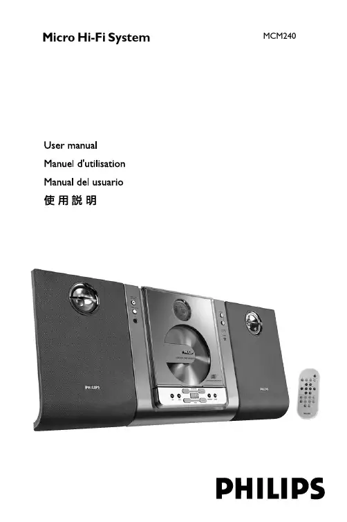
Micro Hi-Fi SystemMCM240lilIndex English------------------------------------------------6Français--------------------------------------------21Español---------------------------------------------3651目錄一般事項環保資訊 (52)隨機配件 (52)安全須知 (52)準備工作背面連接.............................................................53 – 54自選附加設備的連接 (54)將其他設備連接到本機使用遙控器之前 (54)更換遙控器電池(鋰電池 CR2025) (54)控制鍵主機和遙控器上的控制鍵 (55)基本功能開機 (56)將本機切換至待機模式 (56)省電自動待機 (56)調節音量與音效 (56)CD/MP3-CD 光碟操作裝入光碟 (57)基本的播放控制 (57)播放 MP3 光碟 (58)不同的播放模式:亂序 (SHUFFLE)和重複(REPEAT) 播放 (58)編輯光碟曲目播放清單 (58)查看曲目播放清單 (59)刪除曲目播放清單 (59)電台接收調諧選台 (60)預設電台 (60)自動預設電台手動預設電台選擇預設電台 (60)改變調諧頻階 (61)時鐘/計時器設定時鐘 (62)查看時鐘 (62)設定計時器 (62)開啟或關閉計時器(TIMER) (62)開啟或關閉關機計時器(SLEEP) (63)技術規格 (64)維護保養 (64)故障排除 (65)一般事項重要事項!請注意位於本機底部的電壓選擇器已被廠家預設為 220V。
若你的國家使用 110V-127V電壓,請在開啟本機前將電壓選擇器的電壓設定為 110V-127V。
I-240W-Q_I-240E-Q用户手册

GPON 终端用户手册
1 范围
本文档对于家庭网关设备 I-240W-Q 的操作使用介绍除 WLAN 和 USB 部 分外,均适用于 I-240E-Q(不带 WLAN 和 USB 的接口及相关功能)。
3 产品介绍 ............................................................................................ 3
3.1 产品简介 .................................................................................... 3 3.2 产品特点 .................................................................................... 3 3.3 产品外观 .................................................................................... 4 3.4 指示灯说明 ................................................................................ 4 3.5 接口说明 .................................................................................... 6 3.6 缺省设置 .................................................................................... 7
胜利仪器 VICTOR 240.240S.270.270S双通道系列示波器 说明书

2022.11版本V1.0.6深圳市驿生胜利科技有限公司版权所有,保留所有权利。
VICTOR产品受专利权的保护,包括已取得的和正在申请的专利。
本文中的信息将取代所有以前出版资料中的信息。
本手册信息在印刷时是正确的。
然而,深圳市驿生胜利科技有限公司将继续改进产品并且保留在任何时候不经通知的情况下变动规格的权利。
深圳市驿生胜利科技有限公司深圳市福田区泰然六路泰然大厦D座16楼Tel:400-090-0306TEL:*************82425036Web: E-mail:***********************保修概要本公司保证,本产品从本公司最初购买之日起3年(配件1年)期间,不会出现材料和工艺缺陷。
配件如表笔、适配器等保修期1年。
本有限保修仅适于原购买者且不得转让第三方。
如果产品在保修期内确有缺陷,则本公司将按照完整的保修声明所述,提供维修或更换服务。
如果在适用的保修期内证明产品有缺陷,本公司可自行决定是修复有缺陷的产品且不收部件和人工费用,还是用同等产品(由本公司决定)更换有缺陷的产品。
本公司作保修用途的部件、模块和更换产品可能是全新的,或者经维修具有相当于新产品的性能。
所有更换的部件、模块和产品将成为本公司的财产。
为获得本保证承诺的服务,客户必须在适用的保修期内向本公司通报缺陷,并为服务的履行做适当安排。
客户应负责将有缺陷的产品装箱并运送到本公司指定的维修中心,同时提供原购买者的购买证明副本。
本保证不适用于由于意外、机器部件的正常磨损、在产品规定的范围之外使用、使用不当或者维护保养不当或不足而造成的任何缺陷、故障或损坏。
本公司根据本保证的规定无义务提供以下服务:a)维修由非本公司服务代表人员对产品进行安装、维修或维护所导致的损坏;b)维修由于使用不当或与不兼容的设备连接造成的损坏;c)维修由于使用非本公司提供的电源而造成的任何损坏或故障;d)维修已改动或者与其他产品集成的产品(如果这种改动或集成会增加产品维修的时间或难度)。
福禄克 PRV240FS 说明页 说明书
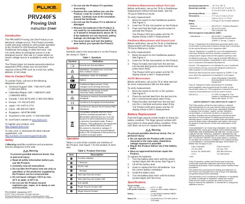
PRV240FSProving UnitInstruction Sheet IntroductionThe PRV240FS Proving Unit (the Product) is an electronic voltage source. This Product provides a safe and easy method to verify proper operation of the T6-600/T6-1000 Electrical Tester with FieldSense technology or other test tools. Useit to verify either an energized source or a de-energized source. Also use it in cases where no known voltage source is available to verify a test tool.The Product does not require personal protective equipment (PPE) unless your environment requires minimal PPE such as a hard hat, safety glasses, or ear plugs.How to Contact FlukeTo contact Fluke, call one of the following telephone numbers:●Technical Support USA: 1-800-44-FLUKE(1-800-443-5853)●Calibration/Repair USA: 1-888-99-FLUKE(1-888-993-5853)●Canada: 1-800-36-FLUKE (1-800-363-5853)●Europe: +31 402-675-200●Japan: +81-3-6714-3114●China: +86-400-921-0835●Singapore: +65-6799-5566●Anywhere in the world: +1-425-446-5500Or, visit Fluke's website at .To register your product, visit.To view, print, or download the latest manual supplement, visit/usen/support/manuals. SafetyA Warning identifies conditions and procedures that are dangerous to the user.WarningTo prevent possible electrical shock, fire,or personal injury:●Read all safety information before youuse the Product.●Carefully read all instructions.●Do not alter the Product and use only asspecified, or the protection supplied bythe Product can be compromised.●Do not touch voltages >30 V ac rms,42 V ac peak, or 60 V dc.●Do not use the Product aroundexplosive gas, vapor, or in damp or wetenvironments.PN 4919689 September 2017© 2017 Fluke Corporation. All rights reserved.Product specifications are subject to change without notice.All product names are trademarks of their respective companies.●Do not use the Product if it operatesincorrectly.●Examine the case before you use theProduct. Look for cracks or missingplastic. Carefully look at the insulationaround the terminals.●Do not use the Product if it is altered ordamaged.●Remove the batteries if the Product isnot used for an extended period of time,or if stored in temperatures above 50 °C.If the batteries are not removed, batteryleakage can damage the Product.●You must close and lock the batterydoor before you operate the Product.SymbolsSymbols used in the instructions or on the Productare shown in Table 1.OperationTable 2 is a list of the controls and interface ofthe Product. See Figure 1 for the location of eachitem.Table 2. Product OverviewItem DescriptionA Function selectionB+ TerminalC AC/DC LEDD − TerminalE Test Lead Ground ContactF Test Lead Ground Contact LEDG Fork saddleH Finger Ground Contact LEDI Finger Ground ContactFieldSense Measurement without Test LeadBefore verification, set up the T6 for a FieldSensemeasurement without the test leads. See theT6Quick Reference Guide.To verify measurement:1. Move the switch to the FieldSense position.See Figure 3.2. Insert the T6 fork into position on the Product.3. Push and hold the finger ground contact toactivate the Product.The Product LED turns green and the T6display shows a 240 V measurement.FieldSense Measurement with Ground LeadBefore verification, set up the T6 for a FieldSensemeasurement with the ground lead. See theT6Quick Reference Guide.To verify measurement:1. Move the switch to the FieldSense position.See Figure 4.2. Insert the T6 fork into position on the Product.3. Place the black test lead from the test toolinto the test lead ground contact terminal andpress down firmly.The Product LED turns green and the T6display shows a 240 V measurement.AC/DC MeasurementBefore verification, set up the T6 or other test toolfor ac/dc measurement with the test leads.To verify measurement:1. Move the switch to the AC or DC position.See Figure 5.2. Place the red test lead from the test tool intothe (+) terminal and press down firmly.3. Place the black test lead from the test toolinto the (-) terminal and press down firmly.The Product LED turns green and the T6display shows a 240 V measurement.Battery ReplacementPush the finger ground contact button to check thebattery condition. The finger ground contact LEDturns green to show good battery condition. If theLED does not turn on, replace the batteries.WarningTo prevent possible electrical shock, fire, orpersonal injury:●Do not operate the Product with coversremoved or the case open. Hazardousvoltage exposure is possible.●Repair the Product before use if the batteryleaks.●Have an approved technician repair theProduct.To replace the batteries:1. Turn the battery-door latch until the unlocksymbol aligns with the arrow. See Figure 2.2. Lift off the battery door.3. Insert or replace the four AA batteries. Usethe correct battery orientation.4. Install the battery door.5. Turn the battery-door latch until the lockedsymbol aligns with the arrow.SpecificationsOutput voltage240 V ac rms or dc ...........±10 % ≥1 MΩLED power indicator.........Turns on when output voltage ispresentBattery ...................................4 x AA Alkaline batteries NEDA15 A IEC LR6Battery life .............................3 hr based on a 10 s test cycle or1100 testsOperating temperature.....-10 °C to +50 °COperating humidity...........0 % to 90 % (0 °C to 35 °C)0 % to 70 % (35 °C to 55 °C)Operating altitude.............2000 mDimensions .......................11.7 cm x 7.4 cm x 4.5 cm(4.6 in x 2.9 in x 1.75 in)Weight................................0.32 kg (12 oz) includes batteriesSafetyGeneral ............................IEC 61010-1, Pollution Degree 2Measurement ...................IEC 61010-2-030240 Vrms/240 VdcElectromagnetic Compatibility (EMC)International ......................IEC 61326-1: ControlledElectromagnetic EnvironmentCISPR 11: Group 1, Class AGroup 1: Equipment has intentionally generated and/or usesconductively-coupled radio frequency energy that is necessaryfor the internal function of the equipment itself.Class A: Equipment is suitable for use in all establishmentsother than domestic and those directly connected to a low-voltage power supply network that supplies buildings usedfor domestic purposes. There may be potential difficulties inensuring electromagnetic compatibility in other environmentsdue to conducted and radiated disturbances.Caution: This equipment is not intended for use in residentialenvironments and may not provide adequate protection toradio reception in such environments.Emissions that exceed the levels required by CISPR 11 canoccur when the equipment is connected to a test object.Korea (KCC) .......................Class A Equipment (IndustrialBroadcasting & CommunicationEquipment)Class A: Equipment meets requirements for industrialelectromagnetic wave equipment and the seller or usershould take notice of it. This equipment is intended for use inbusiness environments and not to be used in homes.USA (FCC) ..........................47 CFR 15 subpart B. Thisproduct is considered an exemptdevice per clause 15.103.LIMITED WARRANTY AND LIMITATION OF LIABILITYThis Fluke product will be free from defects in materialand workmanship for one year from the date of purchase.This warranty does not cover fuses, disposable batteries,or damage from accident, neglect, misuse, alteration,contamination, or abnormal conditions of operation orhandling. Resellers are not authorized to extend any otherwarranty on Fluke’s behalf. To obtain service during thewarranty period, contact your nearest Fluke authorized servicecenter to obtain return authorization information, then sendthe product to that Service Center with a description of theproblem.THIS WARRANTY IS YOUR ONLY REMEDY. NO OTHERWARRANTIES, SUCH AS FITNESS FOR A PARTICULARPURPOSE, ARE EXPRESSED OR IMPLIED. FLUKE IS NOTLIABLE FOR ANY SPECIAL, INDIRECT, INCIDENTAL ORCONSEQUENTIAL DAMAGES OR LOSSES, ARISING FROMANY CAUSE OR THEORY. Since some states or countriesdo not allow the exclusion or limitation of an implied warrantyor of incidental or consequential damages, this limitation ofliability may not apply to you.Fluke Corporation Fluke Europe B.V.P.O. Box 9090P.O. Box 1186Everett, WA 98206-90905602 BD EindhovenU.S.A.The Netherlands11/99Fluke Corporation certifies this Product was tested andverified with applicable calibration procedures during themanufacturing process. Fluke’s quality system controls theseprocedures.The instruments used during the testing and calibration ofthis Product are traceable to SI units through internationallyrecognized measurement standards.This document is not a certificate of calibration or traceability.To obtain a certificate of calibration contact the nearestFluke service center to process an order to have yourProduct returned for calibration. A nominal fee is charged forcalibration service.。
UIM243XX使用手册(电压控制).

使用手册UIM243XXA/B 电压调速微型一体化步进电机控制驱动器第 2页M432130315CN UI Robot Technology Co. Ltd[知识产权保护声明 ]使用 UIROBOT 产品前请注意以下三点:• UIROBOT 的产品均达到 UIROBOT 使用手册中所述的技术功能要求。
• UIROBOT 愿与那些注重知识产权保护的客户合作。
• 任何试图破坏 UIROBOT 器件代码保护功能的行为均可视为违反了知识产权保护法案和条列。
如果这种行为导致在未经 UIROBOT 授权的情况下,获取软件或其他受知识产权保护的成果, UIROBOT 有权依据该法案提起诉讼制止这种行为。
[免责声明 ]本使用手册中所述的器件使用信息及其他内容仅为您提供便利,它们可能在未来版本中被更新。
确保应用符合技术规范,是您自身应负的责任。
UIROBOT 对这些信息不作任何形式的声明或担保,包括但不限于使用情况、质量、性能、适销性或特定用途的适用性的声明或担保。
UIROBOT 对因这些信息及使用这些信息而引起的后果不承担任何责任。
如果将 UIROBOT 器件用于生命维持和 /或生命安全应用, 一切风险由买方自负。
买方同意在由此引发任何一切伤害、索赔、诉讼或费用时,会维护和保障 UIROBOT 免于承担法律责任和赔偿。
未经 UIROBOT 同意,不得以任何方式转让任何许可证。
[商标和外观设计声明 ]UIROBOT 的名称和徽标组合为 UIROBOT Ltd.在中国和其他国家或地区的注册商标。
UIROBOT 的 UIM24XXX 系列步进电机(控制驱动器和 UIM25XX 系列转换控制器外观设计均以申请专利保护。
[ UIM243XXA/B产品订购说明 ]在订购 UIM243XX 系列产品时请按以下格式提供产品号,以便我们准确及时地为您提供产品:UID24302产品牌号注:⑤如果不填,可以省略该方框。
各选项默认值为:T(螺纹接线端子, A (片上电位器, 1(J1短接以及 1(J2短接。
I-240W-Q家庭网关维护手册

I-240W-Q家庭网关维护手册登陆I-240W-Q●打开浏览器, 输入“http://192.168.1.1” (I-240W-Q 默认IP地址)。
●连接时需要一个用户名和密码。
●默认的超级用户名和密码为“telecom admin” and “nE7jA%5m”。
当你以超级用户名登陆后,你可以查询,配置和修改所有的设置。
为了使你做的配置和修改生效,有时你必需重新启动。
系统状态设备信息在“设备信息”选项下,将显示如下页面。
这个页面包含以下信息:●设备型号:●设备标识号:●硬件版本:●软件版本:用户侧信息宽待语音信息宽待语音信息远程管理状态网络网络-宽带设置点击网络-宽带设置-Internet连接,配置PPPoE选择模式RouteVlan ID:如果启用Vlan,输入VLAN 标记的值,VLAN 标记仅仅对PPPoE, MER and Bridge 是有效的。
PPP 用户名: ISP 提供正确的用户名.PPP Password: ISP提供正确的密码PPPoE Service Name: ISP 提供PPPoE服务名称选择模式BridgeVlan ID:如果启用Vlan,输入VLAN 标记的值,VLAN 标记仅仅对PPPoE, MER and Bridge 是有效的绑定设置LAN侧地址配置WLAN配置在这个页面你可以配置基本的无线网络设置。
你可以启用或禁用无线功能,隐藏访问点,设置无线网络名(也就是SSID)。
下面是不同选项的说明:●启用无线: 如果启用无线,隐藏访问点,SSID,BSSID,信道,54g™速率,多播速率,54g™模式,发送功率,将会显示出来。
●隐藏访问点:Hide Access Point: 选取这个选项,如果你希望隐藏你路由器的访问点,使得中端无法通过被动扫描来获得你的SSID。
●SSID: SSID (Service Set Identification)一个无线网络中所有设备共享的唯一的名字。
美格仕MR-240數碼錄音機使用手冊说明书
● 播放中或待機狀態下向音量 (+),音量 (-) 方向推 JOG 按鍵,螢幕上會表示音量等級, 可以調節音量。
● 開機後,音量為 11 級以上時會自動調節到 10 級,此為防止聽力損傷。
Įࢰณ̈į
Įࢰณ̂į
11. 查看錄音時間
● 待機狀態下,短按模式按鍵可顯示選好的錄音文件時間,錄音文件會有 1~3 秒左右誤差。
和 “PLAY” 圖示會閃燈同時播放文件 10 秒。 (3) 在播放文件 10 秒鐘狀態下,短按刪除 (ERASE) 按鍵進行刪除文件,進行中按其他按
鍵或刪除按鍵會取消此功能。
★全部文件和資料夾刪除請參照模式設定。 ĮӁੵពϯ൪ࢬį
注意
★刪除的文件無法恢復,刪除前請確認是否有重要的文件。
★刪除文件後,文件數量會減少一個,文件號碼會自動前移。
例:如果刪除 001,002 會變成 001,003 變成 002。
)Ӂੵ݈͛Іཱིቅ*
Ӂੵ
)Ӂੵ͛ޢІཱིቅ*
15. 上傳 / 下載文件
● 使用 USB 線將耳機插口與 PC USB 接線端連接(如右圖 ),
連接後 LCD 螢幕上會顯示
資訊。
● 待機數分鐘後,電腦會將本產品自動辨識為卸除式儲存裝置。
A , B 文件夾:A-R001.MP3 或 B-R001.MP3,PCM 文件夾:PCM-R001.wav ( 如果開始錄音後 3 秒以內停止的話,不會儲存文件) ● 出廠錄音模式設定於 MP3 格式 “HQ”。 ● 如果記憶體不足超過能保存的數量會表示 “FULL”。
ĮMP3ॾё!ᐂࢰ/ޞ፟ېၗį ĮPCMॾё!ᐂࢰ/ޞ፟ېၗį
資訊。
● 長按播放按鍵 3 秒以上本機會進入到待機狀態,您可以錄音,播放。 ● 使用 PC USB 電源進入到待機狀態時您不可上傳 / 下載檔案。 ● 將本機從電腦分離後再連接時,進入到 USB 連接狀態您可以上傳 / 下載檔案。
I-240W-Q_I-240E-Q用户手册
I-240W-Q I-240E-Q 用户手册目录1 范围 (1)2注意事项 (2)3产品介绍 (3)3.1 产品简介 (3)3.2 产品特点 (3)3.3 产品外观 (4)3.4 指示灯说明 (4)3.5 接口说明 (6)3.6 缺省设置 (7)4 安装与连线 (7)4.1 安装在墙面上 (7)4.2 连接线缆 (10)连接到局域网 (11)连接光纤 (11)连接电源线 (11)4.3 无线连接 (11)4.4 上电检查 (14)5 设备功能 (15)5.1 业务功能 (15)5.2 PON 接口功能 (15)PON 口物理参数 (15)GPON 服务质量功能 (15)5.3 以太网接口功能 (16)5.4 POTS 接口功能 (16)5.5 2.4G 无线接入接口 (17)5.6 USB 接口 (17)5.7 操作,管理和维护功能 (17)6 设备应用模式 (19)7 网络配置管理介绍 (20)7.1 登录ONU 前的准备 (20)7.2 登录ONU (21)7.3 系统状态 (22)7.3.1 设备信息 (22)7.3.2 网络侧信息 (23)7.3.3 用户侧信息 (24)7.3.4 宽带语音信息 (25)7.4 网络 (27)7.4.1 WLAN 配置 (27)7.4.2 远程管理 (30)7.5 安全 (31)7.5.1 广域网访问设置 (31)7.5.2 防火墙 (32)7.5.3 MAC 过滤 (33)7.6 应用 (34)7.7 管理 (35)7.7.1 用户管理 (35)7.7.2 设备管理 (35)7.8 帮助 (37)8 技术指标和参数 (38)8.1 技术规格 (38)8.2 遵循的标准 (39)9 FAQ 和故障排除 (40)1范围本文档对于家庭网关设备I-240W-Q 的操作使用介绍除WLAN 和USB 部分外,均适用于I-240E-Q(不带WLAN 和USB 的接口及相关功能)。
INA240EVM 用户指南说明书
INA240EVM User's Guide User's GuideLiterature Number:SBOU177September20162SBOU177–September 2016Submit Documentation FeedbackCopyright ©2016,Texas Instruments IncorporatedINA240EVM User's GuideAll trademarks are the property of their respective er's GuideSBOU177–September 2016INA240EVM User's GuideThis user’s guide describes the characteristics,operation,and use of the INA240EVM evaluation module.This guide discusses how to set up and configure the hardware.Throughout this document,the terms evaluation board ,evaluation module ,and EVM are synonymous with the INA240EVM .This document includes an electrical schematic,printed circuit board (PCB)layout drawings,and a parts list for the EVM. Overview3SBOU177–September 2016Submit Documentation FeedbackCopyright ©2016,Texas Instruments IncorporatedINA240EVM User's Guide1OverviewThe INA240device is a voltage output current shunt monitor that senses drops across shunts at specified common-mode voltages from –4V to 80V,independent of the supply voltage.NOTE:Note that this EVM limits the maximum common-mode voltage to 70V with clamping diodesD1and D2.The device operates from a single 2.7-V to 5.5-V power supply,drawing a typical supply current ofapproximately 1mA.The INA240EVM package includes one large PCB that can be broken apart into four separate PCBs,one for each of the four gain versions (INA240A1/A2/A3/A4).The EVM includes test points for external hardware connections,placeholder pads to add filtering components,and surface-mount resistors for ease of setting the reference.1.1INA240EVM Kit ContentsTable 1lists the contents of the INA240EVM kit.The included hardware is pictured on the front page that shows only one of the four INA240devices and the associated EVM hardware.Contact the nearest Texas Instruments Product Information Center if any component is missing.Take care to check the INA240Product Folder on the TI web site at for any further information regarding this product.Table 1.INA240EVM Kit ContentsITEMQUANTITYINA240A1EVM test board 1INA240A2EVM test board 1INA240A3EVM test board 1INA240A4EVM test board11.2Related Documentation from Texas InstrumentsThe following documents provide information regarding Texas Instruments'integrated circuits used in the assembly of the INA240EVM.This user's guide is available from the TI web site under literature number SBOU177.Any letter appended to the literature number corresponds to the document revision that is current at the time of the writing of this document.Newer revisions may be available from the TI web site ( ),or by calling the Texas Instruments'Literature Response Center at (800)477-8924or the Product Information Center at (972)644-5580.When ordering,identify the document by title and literature number.Table 2lists related documentation for this device.Table 2.Related DocumentationDOCUMENTLITERATURE NUMBERINA240Wide Common-Mode Range,Voltage Output,High-or Low-Side Bidirectional,Zero-Drift,Current-ShuntMonitorSBOS662INA240EVM Hardware 4SBOU177–September 2016Submit Documentation FeedbackCopyright ©2016,Texas Instruments IncorporatedINA240EVM User's Guide2INA240EVM HardwareThe INA240EVM requires a 2.7-V to 5.5-V power supply.Connect the VIN+and VIN–pins across an external shunt resistor in series with a –4-V to 70-V supply to determine the current flowing through the e a voltmeter on the OUT pin to measure the voltage output.The REF1and REF2pins set the output reference.2.1Theory of Operation for the INA240EVMA block diagram of the INA240EVM test board hardware is shown in Figure 1.The INA240test board contains test points that provide access to all eight pins of the INA240device for evaluation.A footprint is provided for the input filtering circuitry.The REF1and REF2pins are equipped with jumpers to set the output reference to VS,GND,half VS,or any desired external reference level.Figure 1.INA240EVM Test Board Block Diagram2.2INA240EVM FeaturesThe INA240EVM provides a basic functional evaluation of the INA240.The fixture layout is not intended to be a model for the target circuit,or laid out for electromagnetic compatibility (EMC)testing.The layout of the INA240EVM printed circuit board (PCB)provides the following features:•Simple access to all device pins •Multiple input signal options •Space for optional input filtering •Configurable reference pins INA240EVM Hardware5SBOU177–September 2016Submit Documentation FeedbackCopyright ©2016,Texas Instruments IncorporatedINA240EVM User's GuideThe INA240EVM connects to both sides of a remote shunt resistor to measure current,or omits the shunt resistor and applies a differential voltage directly to the device inputs.This flexibility allows the testing of device operation in a simulated manner and an actual application.See INA240Wide Common-Mode Range,Voltage Output,High-or Low-Side Bidirectional,Zero-Drift,Current-Shunt Monitor (SBOS662)for comprehensive information about the INA240family.INA240EVM Hardware 6SBOU177–September 2016Submit Documentation FeedbackCopyright ©2016,Texas Instruments IncorporatedINA240EVM User's Guide2.3Quick-Start Setup and UseFollow the procedure listed below to set up and use the INA240EVM:1.Connect an external dc supply voltage between2.7-V and 5.5-V to the VS test point.2.Connect the desired input to input test points,IN+and IN-.This input is a remote shunt resistor or a differential voltage source with a common-mode voltage of –4V to 70V referenced to GND.Note that the INA240device has a rated common-mode voltage of 80V,however the full 80V is unavailable on the EVM because the input is limited by the D1and D2clamping diodes.2.4Voltage InputsThe IN+and IN–test points connect to a remote shunt resistor or a differential voltage source.The voltage differential is multiplied by the device gain of the INA240device.There are four devices in this family,which include:the INA240A1with 20-V/V gain,the INA240A2with 50-V/V gain,the INA240A3with 100-V/V gain,and the INA240A4with 200-V/V gain.The full-scale sense input voltage (V SENSE )is defined as VIN+–VIN–,and has a maximum input of (V+–0.20)per gain to achieve linear output.The minimum voltage output is 10mV.2.5Setting the ReferenceThe INA240output is referenced to the voltage level defined by the REF1and REF2pins.The tworeference pins independently connect to VS,GND,or an external source.It is possible to set the reference level to VS,GND,half VS,or an arbitrary level through external sources. Schematic,PCB Layout,and Bill of Materials7SBOU177–September 2016Submit Documentation FeedbackCopyright ©2016,Texas Instruments IncorporatedINA240EVM User's Guide3Schematic,PCB Layout,and Bill of Materials 3.1SchematicFigure 2shows the complete schematic of the INA240test board.Only the EVM associated withINA240A1is shown.C1and C3are bypass capacitors for VS.C2,R1,and R2create an optional filter for the VIN+and VIN–inputs.R3is an optional shunt resistor for the INA input.R4through R7are jumpers that enable the flexibility in configuring the reference level.The reference is set by splitting VS by default.D1and D2are clamps that limit the maximum common-mode voltage to 70V,although the INA240is rated at 80V.Figure 2.INA240EVM Test Board SchematicSchematic,PCB Layout,and Bill of Materials 8SBOU177–September 2016Submit Documentation FeedbackCopyright ©2016,Texas Instruments IncorporatedINA240EVM User's Guide3.2PCB LayoutFigure 3shows the component placement on the INA240EVM test board.There are no components on the bottom layer.Figure 4and Figure 5illustrate the top and bottom layers of the test board,respectively.Figure 3.INA240EVM Component PlacementFigure 4.PCB Top Layer Schematic,PCB Layout,and Bill of Materials9SBOU177–September 2016Submit Documentation FeedbackCopyright ©2016,Texas Instruments IncorporatedINA240EVM User's GuideFigure 5.PCB Bottom LayerSchematic,PCB Layout,and Bill of Materials 10SBOU177–September 2016Submit Documentation FeedbackCopyright ©2016,Texas Instruments IncorporatedINA240EVM User's Guide3.3Bill of MaterialsTable 3lists the bill of materials (BOM)for the INA240test board,which includes four identical PCBs,one for each of the gain versions in the INA240family.Table 3.INA240Test Board BOMQUANTI TYREFDES DESCRIPTIONPART NUMBER MANUFACTURER 4C1CAP,CERM,0.1µF,16V,+/-5%,X7R,06030603YC104JAT2A AVX 4C3CAP,CERM,1µF,25V,+/-10%,X5R,080508053D105KAT2A AVX 8D1,D2Diode,TVS,Uni,70V,600W,SMB SMBJ70A-13-F Diodes Inc.16R1,R2,R4,R7RES,0,5%,0.1W,0603ERJ-3GEY0R00V Panasonic 16H9,H10,H11,H12Bumpon,Hemisphere,0.44×0.20,ClearSJ-5303(CLEAR)3M1U1Wide Common-Mode Range,Voltage Output,High or Low-Side Bi-Directional Zero-Drift Current Shunt Monitor,PW0008AINA240A1PW ERJ-6GEY0R00V 1U2Wide Common-Mode Range,Voltage Output,High or Low-Side Bi-Directional Zero-Drift Current Shunt Monitor,PW0008AINA240A2PW Texas Instruments 1U3Wide Common-Mode Range,Voltage Output,High or Low-Side Bi-Directional Zero-Drift Current Shunt Monitor,PW0008AINA240A3PW Texas Instruments 1U4Wide Common-Mode Range,Voltage Output,High or Low-Side Bi-Directional Zero-Drift Current Shunt Monitor,PW0008AINA240A4PWTexas InstrumentsIMPORTANT NOTICETexas Instruments Incorporated and its subsidiaries(TI)reserve the right to make corrections,enhancements,improvements and other changes to its semiconductor products and services per JESD46,latest issue,and to discontinue any product or service per JESD48,latest issue.Buyers should obtain the latest relevant information before placing orders and should verify that such information is current and complete.All semiconductor products(also referred to herein as“components”)are sold subject to TI’s terms and conditions of sale supplied at the time of order acknowledgment.TI warrants performance of its components to the specifications applicable at the time of sale,in accordance with the warranty in TI’s terms and conditions of sale of semiconductor products.Testing and other quality control techniques are used to the extent TI deems necessary to support this warranty.Except where mandated by applicable law,testing of all parameters of each component is not necessarily performed.TI assumes no liability for applications assistance or the design of Buyers’products.Buyers are responsible for their products and applications using TI components.To minimize the risks associated with Buyers’products and applications,Buyers should provide adequate design and operating safeguards.TI does not warrant or represent that any license,either express or implied,is granted under any patent right,copyright,mask work right,or other intellectual property right relating to any combination,machine,or process in which TI components or services are rmation published by TI regarding third-party products or services does not constitute a license to use such products or services or a warranty or endorsement e of such information may require a license from a third party under the patents or other intellectual property of the third party,or a license from TI under the patents or other intellectual property of TI.Reproduction of significant portions of TI information in TI data books or data sheets is permissible only if reproduction is without alteration and is accompanied by all associated warranties,conditions,limitations,and notices.TI is not responsible or liable for such altered rmation of third parties may be subject to additional restrictions.Resale of TI components or services with statements different from or beyond the parameters stated by TI for that component or service voids all express and any implied warranties for the associated TI component or service and is an unfair and deceptive business practice. TI is not responsible or liable for any such statements.Buyer acknowledges and agrees that it is solely responsible for compliance with all legal,regulatory and safety-related requirements concerning its products,and any use of TI components in its applications,notwithstanding any applications-related information or support that may be provided by TI.Buyer represents and agrees that it has all the necessary expertise to create and implement safeguards which anticipate dangerous consequences of failures,monitor failures and their consequences,lessen the likelihood of failures that might cause harm and take appropriate remedial actions.Buyer will fully indemnify TI and its representatives against any damages arising out of the use of any TI components in safety-critical applications.In some cases,TI components may be promoted specifically to facilitate safety-related applications.With such components,TI’s goal is to help enable customers to design and create their own end-product solutions that meet applicable functional safety standards and requirements.Nonetheless,such components are subject to these terms.No TI components are authorized for use in FDA Class III(or similar life-critical medical equipment)unless authorized officers of the parties have executed a special agreement specifically governing such use.Only those TI components which TI has specifically designated as military grade or“enhanced plastic”are designed and intended for use in military/aerospace applications or environments.Buyer acknowledges and agrees that any military or aerospace use of TI components which have not been so designated is solely at the Buyer's risk,and that Buyer is solely responsible for compliance with all legal and regulatory requirements in connection with such use.TI has specifically designated certain components as meeting ISO/TS16949requirements,mainly for automotive use.In any case of use of non-designated products,TI will not be responsible for any failure to meet ISO/TS16949.Products ApplicationsAudio /audio Automotive and Transportation /automotiveAmplifiers Communications and Telecom /communicationsData Converters Computers and Peripherals /computersDLP®Products Consumer Electronics /consumer-appsDSP Energy and Lighting /energyClocks and Timers /clocks Industrial /industrialInterface Medical /medicalLogic Security /securityPower Mgmt Space,Avionics and Defense /space-avionics-defense Microcontrollers Video and Imaging /videoRFID OMAP Applications Processors /omap TI E2E Community Wireless Connectivity /wirelessconnectivityMailing Address:Texas Instruments,Post Office Box655303,Dallas,Texas75265Copyright©2016,Texas Instruments Incorporated。
优爱宝 微型智能步进电机驱动器 说明书
超小体积/高性能/8A峰值电流/多种通讯接口电机一体化设计,自主知识产权适配42/57/85/110等各款步进电机优爱宝UIM24002型 / UIM24004型 / UIM24008型并口系列微型步进电机驱动器● 体积小 42.3 mm x 42.3 mm x 13.5 mm ● 与电机一体化设计,亦可分立于电机工作● 10~40VDC供电,2A/4A/8A峰值可调电流,1~16 细分● H桥双极恒流,在线可控脱机● 输入信号光电隔离,标准共阳极单脉冲● 全密闭机壳产品特点UIM24002 / UIM24004 / UIM24008 是一系列超小型高性能的步进电机驱动器。
其最大特点在于体积小,驱动能力强。
加上对应的法兰后,能直接固定在 42 / 57 / 85 / 110 等系列的步进电机上。
其本身厚度小于14 mm。
UIM24002 能提供 0~2A 可调峰值电流;UIM24004 能提供 0~4A 可调峰值电流;UIM24008 能提供 0~8A 可调峰值电流。
其高速电流补偿功能,能补偿电机高速转动时反电动势造成的影响。
除UIM24002使用 10V ~35V 外,直流供电这个系列的驱动器使用 10V ~40V 直流供电。
驱动器外壳为全铝合金铸件,坚固耐用,散热性能好。
产品简介性能指标绝对最大参数工作电气性能(环境温度25℃时)通讯方式(环境温度25℃时)长期工作在绝对最大参数或以上可能损坏驱动器供电电压 40VDC (UIM24002型为35VDC)储藏环境温度 -20℃ ~ +125℃工作温度-20℃ ~ +85℃供电电源电压 10V ~ 40VDC (UIM24002型为8V ~ 35VDC)输出电机电流 峰值2A / 4A / 8A 每相(Max ) 驱动方式 恒相流PWM 控制励磁方式 整步,半步,4 细分,16 细分绝缘电阻 在常温常压下>100MΩ绝缘强度在常温常压下0.5KV , 1 分钟并口通讯步进脉冲、方向、脱机 三种信号微部细分 由板上拨码开关设定使用环境及参数冷却方式 自然冷却使用环境 场合 尽量避免粉尘、油雾及腐蚀性气体温度 -20 ℃ ~ +50 ℃湿度 <80%RH,无凝露,无结霜震动 1G Max保存温度 -20 ℃ ~ +125 ℃外形尺寸 42.3mm x 42.3mm x 13.5mm 重量0.1 kg实际电流由可调电阻设定U IM 240xx 驱动器10~40V直流电源步进电机A+ A- B+ B-1 2 DC+ DC-用户主机3.3~5V 方向 步进脉冲 脱机共用端 5 4 63典型接线图驱动器外观尺寸与一元硬币比较图UIM24104 / UIM24108是基于RS232通讯的小体积智能型步进电机驱动器。