A.749(18)船舶完整稳性英文版
中文IMO resolution (2010-1-1 to 2010-7-1) list

MSC.270(85)
MSC.201(81)
1974 SOLAS公约修正 案 ADOPTION OF AMENDMENTS TO THE INTERNATIONAL CONVENTION FOR THE SAFETY OF LIFE AT SEA, 1974, AS AMENDED MEPC.184(59) 经修订的废气清洁系统 导则 2009 GUIDELINES FOR EXHAUST GAS CLEANING SYSTEMS MSC.207(81) LAS规则 ADOPTION OF AMENDMENTS TO THE INTERNATIONAL LIFE-SAVING APPLIANCE (LSA) CODE MEPC.181(59) 经修订MARPOL附则VI 的2009年港口国检查导 则 2009 GUIDELINES FOR PORT STATE CONTROL UNDER THE REVISED MARPOL ANNEX VI MSC.201(81) 1974 SOLAS公约修正 案 ADOPTION OF AMENDMENTS TO THE INTERNATIONAL CONVENTION FOR THE SAFETY OF LIFE AT SEA, 1974, AS AMENDED MSC.269(85) 1974SOLAS公约修正 案 ADOPTION OF AMENDMENTS TO THE INTERNATIONAL CONVENTION FOR THE SAFETY OF LIFE AT SEA, 1974, AS AMENDED MEPC.185(59) VOC管理计划制定导则 GUIDELINES FOR THE DEVELOPMENT OF A VOC MANAGEMENT PLAN
船舶稳性英文稿
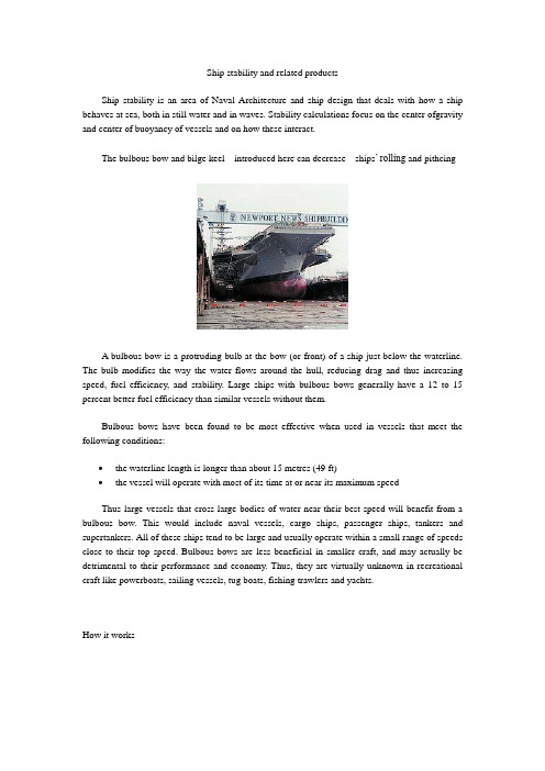
Ship stability and related productsShip stability is an area of Naval Architecture and ship design that deals with how a ship behaves at sea, both in still water and in waves. Stability calculations focus on the center ofgravity and center of buoyancy of vessels and on how these interact.The bulbous bow and bilge keel introduced here can decrease ships’ rolling and pithcingA bulbous bow is a protruding bulb at the bow (or front) of a ship just below the waterline. The bulb modifies the way the water flows around the hull, reducing drag and thus increasing speed, fuel efficiency, and stability. Large ships with bulbous bows generally have a 12 to 15 percent better fuel efficiency than similar vessels without them.Bulbous bows have been found to be most effective when used in vessels that meet the following conditions:∙the waterline length is longer than about 15 metres (49 ft)∙the vessel will operate with most of its time at or near its maximum speedThus large vessels that cross large bodies of water near their best speed will benefit from a bulbous bow. This would include naval vessels, cargo ships, passenger ships, tankers and supertankers. All of these ships tend to be large and usually operate within a small range of speeds close to their top speed. Bulbous bows are less beneficial in smaller craft, and may actually be detrimental to their performance and economy. Thus, they are virtually unknown in recreational craft like powerboats, sailing vessels, tug boats, fishing trawlers and yachts.How it worksGraphic demonstrating the how the bulbous bow influences water flowIn a conventionally shaped bow, a bow wave forms immediately before the bow. When a bulb is placed below the water ahead of this wave, water is forced to flow up over the bulb. If the trough formed by water flowing off the bulb coincides with the bow wave, the two partially cancel out and reduce the vessel's wake. While inducing another wave stream saps energy from the ship, canceling out the second wave stream at the bow changes the pressure distribution along the hull, thereby reducing wave resistance. The effect that pressure distribution has on a surface is known as the form effect.Some explanations note that water flowing over the bulb depresses the ship's bow and keeps it trimmed better. Since many of the bulbous bows are symmetrical or even angled upwards which would tend to raise the bow further, the improved trim is likely a by-product of the reduced wave action as the vessel approaches hull speed, rather than direct action of water flow over the bulb.A sharp bow on a conventional hull form would produce waves and low drag like a bulbous bow, but waves coming from the side would strike it harder. Also, in heavy seas, water flowing around the bulb dampens pitching movements like a squiggle keel. The blunt bulbous bow also produces higher pressure in a large region in front, making the bow wave start earlier.The addition of a bulb to a ship's hull increases its overall wetted area. The problem is that as wetted area increases, so does drag. At greater speeds and in larger vessels it is the bow wave that is the greatest force impeding the vessels forward motion through the water. Thus the beneficial effects of Bulbous bows have a range at which they are seen, generally the upper end of performance for the vessel. For a vessel that is small or spends a great deal of its time at a slow speed, the increase in drag will not offset the benefit in dampening bow wave generation. As the wave counter effects are only significant at the vessel's higher range of speed, bulbous bows are not energy efficient when the vessel cruises outside of these ranges, specifically at lower speeds.DevelopmentThe bulbous bow concept is credited to David W. Taylor, a naval architect who served as Chief Constructor of the Navy [USA] during the First World War. The concept (known as a bulbous forefoot) was first introduced in his design of the USS Delaware, which entered service in 1910. The bow design did not initially enjoy wide acceptance. This all changed in the 1920s, with Germany's launching the Bremen and the Europa. They were referred to as Germany's North Atlantic grey hounds, two large commercial ocean liners that competed for the trans-Atlantic passenger trade. Both ships won the coveted Blue Riband, the Bremen in 1929 with a crossingspeed of 27.9 knots (51.7 km/h; 32.1 mph), and the Europa exceeding her in 1930 with a crossing speed of 27.91 knots.The design began to be incorporated elsewhere, as seen in the U.S. built Malolo, President Hoover and President Coolidge, passenger liners launched in the late 1920s and early 1930s. Still the idea was largely viewed as experimental by many ship builders and owners.In 1935 the French superliner Normandie coupled a bulbous forefoot with massive size and a redesigned hull shape. She was able to achieve speeds in excess of 30 knots (56 km/h). The Normandie was famous for many things, among which included her clean entry into the water and markedly reduced bow wave. Normandie's great rival, the British liner Queen Mary achieved equivalent speeds with a non-bulbous traditional stem and hull design. However, a crucial difference lay in the fact that Normandie achieved these speeds with approximately thirty percent less engine horsepower than Queen Mary — and with a corresponding reduction in fuel use.Bulbous bow designs were also independently developed and used by the Japanese Navy. A modest bulbous bow was used in a number of their ship designs, including the light cruiser Ōyodo and the carriers Shōkaku and Taihō. A far more radical bulbous bow design solution was incorporated into their massively large Yamato class battleships, including the Y amato, Musashi and the aircraft carrier Shinano.The modern bulbous bow was developed by Dr. Takao Inui at the University of Tokyo, during the 1950s and 1960s, independently of Japanese naval research. Inui based his research on earlier findings by scientists made after Taylor discovered that ships fitted with a bulbous forefoot exhibited substantially lower drag characteristics than predicted. The bulbous bow concept was first definitively studied by Thomas Havelock, Cyril Wigley and Georg Weinblum, including Wigley's 1936 work "The Theory of the Bulbous Bow and its Practical Application" which examined the issues of wave production and dampening. Inui's initial scientific papers on the effect of bulbous bow on wavemaking resistance were collected into a report published by the University of Michigan in 1960. His work came to widespread attention with his paper "Wavemaking Resistance of Ships" published by the Society of Naval Architects and Marine Engineers in 1962.[6] It was eventually found that drag could be reduced by about 5%. Experimentation and refinement slowly improved the geometry of bulbous bows, but they were not widely exploited until computer modelling techniques enabled researchers at the University of British Columbia to increase their performance to a practical level in the 1980s.Sonar domesSome warships specialized for anti-submarine warfare use a specifically shaped bulb as a hydrodynamic housing for a sonar transducer, which resembles a bulbous bow, but the hydrodynamic effects are only incidental. The transducer is a large cylinder or sphere composed of a phased array of acoustic transducers.[7] The entire compartment is flooded with water and the acoustic window of the bulb is made of fiber-reinforced plastic or another material (such as rubber) transparent to the transmitted and received underwater sounds. The transducer bulb places thesonar equipment at the greatest possible distance from the ships own noise generating propulsion system.Bilge keelA bilge keel is used to reduce the hull's tendency to roll. Bilge keels are employed in pairs (one for each side of the ship). A ship may have more than one bilge keel per side, but this is rare. Bilge keels increase hydrodynamic resistance to rolling, making the ship roll less. Bilge keels are passive stability systems.On commercial shipping the bilge keel is the form of a strake, or small keel or blister,running along much of the length of the hull. They are typically fitted one on each side, low down on the side of the hull, so as not to increase the draft of the vessel. In battleships they were often quite large and used as part of the torpedo protection system.A bilge keel is often in a "V" shape, welded along the length of the ship at the turn of the bilge. Although not as effective as stabilizing fins, bilge keels have a major advantage in their low impact on internal ship arrangements. Unlike fins, bilge keels do not have any components inside the hull that would adversely affect cargo or mission spaces. Like fins, bilge keels have the disadvantage of increasing the hydrodynamic resistance of the vessel, thus hindering forward motion.Design considerationsWhen designing a bilge keel, there are important decisions to consider. To minimize hydrodynamic drag, the bilge keel should be placed in way of a flowline where it does not oppose crossflow. For such a usage the ends of the bilge keel should be tapered and properly faired into the hull. Also, a bilge keel should not protrude from the hull so far that the device could be damaged when the vessel is alongside a pier, even with a few degrees of adverse heel. Bilge keels on commercial vessels should not protrude below the baseline either, where they could bedamaged or fouled by grounding. Note that small bilge keels are often fitted to smaller fishing boats precisely to protect the hull on drying moorings and to help keep the vessel uprightEffectivenessIt is constructed from flat plate so as to present a sharp obstruction to roll motion. The roll damping provided by bilge keels is more than that of barehull ships, but falls short of other roll damping devices. Nevertheless it is considered prudent Naval Architecture to install a bilge keel whenever possible as it is the only device effective in the severest of seas. Bilge keels can also be used in conjunction with other roll damping devices.On sailing yachtsBilge keels are often fitted to smaller sailing yachts. Bilge keels minimise the draft of the vessel compared to a single fin keel thus enabling it to negotiate shallower water. Bilge keels on sailing yachts extend below the lowest point of the hull extending slightly outwards. Such an arrangement also enables the vessel to stand upright on firm sand or mud at drying moorings without the need for detachable legs, and is simpler than retractable fin keels while giving the hull greater protection. Bilge keels are not as effective as central fin keels in preventing leeway (sideways slippage) caused by crosswinds but are preferred by many small craft owners due to their other advantages.。
风帆助航渔船的稳性及经济性分析

风帆助航渔船的稳性及经济性分析苏朝君;马坤【摘要】Sail-assisted ship is an important way to save energy. The paper chooses a squid fishing vessel as research object, selecting NACA0006 sail and arc-shaped sail based on the characteristics of the ship, then using Fluent software to set up sail models, and numerically simulate air dynamic of these two kinds of sails. We can estimate energy-saving per year and the amount of reducing carbon dioxide emissions of the sail-assisted ships according to the results of software. By analysis the stability of sail-assisted squid fishing vessel, it is certain that sail-assisted squid fishing vessel is able to meet stability requirements, as long as reasonable installation and operation of sails.%风帆助航是船舶节能减排的重要途径.本文以1条鱿鱼钓船作为研究对象,根据该船的特点选择NACA0006型帆和圆弧型帆作为辅助风帆,然后利用Fluent软件建立所选风帆模型,对这2种风帆的空气动力性能进行数值模拟计算.根据软件的计算结果估算风帆助航时鱿鱼钓船的每年节油量以及所减少的二氧化碳排放量.通过对风帆助航鱿鱼钓船的稳性进行计算分析,可以确定只要合理地安装和操作风帆,风帆助航渔船是能满足稳性要求的.【期刊名称】《舰船科学技术》【年(卷),期】2012(034)007【总页数】6页(P55-60)【关键词】风帆助航;鱿鱼钓船;数值模拟;稳性;经济性【作者】苏朝君;马坤【作者单位】大连理工大学船舶CAD工程中心,辽宁大连116024;大连理工大学船舶CAD工程中心,辽宁大连116024;大连理工大学工业装备结构分析国家重点实验室,辽宁大连116024【正文语种】中文【中图分类】U664.31随着世界石油资源的日益枯竭和国际油价飞涨,船舶的燃油费用在航运成本中所占的比例越来越高。
船舶破损控制手册的编制

船舶破损控制手册的编制1.船舶破损控制手册编制的法律依据:1.1SOLAS公约的有关规定第Ⅱ-1章第19条“破损控制资料”的第一款。
1.2海安会1245通函(MSC.1/Circ.1245)《向船长提供破损控制图和资料的指南》。
2. 破损控制2.1 破损控制图(见附件2-《DAMAGE CONTROL BOOKLET》最后一页)2.1.1 在船上的放置位置:破损控制图应永久张贴在驾驶室或放在驾驶室易于查阅处。
另外,破损控制图还应永久张贴在货物控制室或放在货物控制室易于查阅处。
2.1.2 破损控制图:为清楚地显示控制图所要求的内容,破损控制图应有合适的比例,但应不小于1:200。
为特殊需要建议采用相同大小的图表。
破损控制图应包括船内轮廓,每层甲板俯视图,以及显示船舶的水密分隔、所有内部水密装置的位置、船舶外壳上的所有门,开启关闭指示器、所有舱底泵和压载泵以及它们的控制装置和相关的阀的位置等内容(请见本手册附图)。
2.1.3对破损控制图的熟悉和掌握:所有的高级船员(包括驾驶员、轮机员在内,以下称高级船员)都要熟悉和掌握船舶破损控制图的内容和控制要求。
为了遵守法规、确保生命、财产的安全,船长应充分重视,并组织全体高级船员学习了解本船破损控制图的全部内容。
2.2 破损控制手册及日常监控管理2.2.1 编制目的:为了满足SOLAS公约的要求,给高级船员提供包含有船舶破损相关资料的小册子,以便他们熟悉和掌握。
平时按职责分工做好预防性的控制工作;一旦船舶发生破损时,可给包括船长在内的高级船员提供有关船舶水密舱室以及维护舱室边界和保持分隔有效性装置的准确信息,判断船舶进水情况的严重性,并立即采取响应的措施,以便快速减轻,可能的话,使船舶损失的稳性得到恢复。
2.2.2 编制方法:本船破损控制图中所述的内容在本手册中重复列出。
在本手册中还包括了控制破损后果的一般指导,规定了有关破损控制要求项目的日常监护分工,确保船舶的破损情况在控制中。
CCS船舶设计建造标准一览表

2008修正案(以MSC.260(84)决议通过,2010年1月1日生效)
2008 Amendments(by MSC.260(84),effective date on 1January 2010)
2006Amendments(by MSC.201(81),effective date on 1 July 2010)
10.2
2006修正案(以MSC.216(82)决议附件3修改,2010年7月1日生效)
2006 Amendments (by MSC.216(82) annex 3,effective date on 1 July 2010)
12.1
1981修正案
1981 Amendments
12.2
1987修正案
1987 Amendments
12.3
1989修正案
1989 Amendments
12.4
1993修正案
1993 Amendments
12.5
2001修正案(以A.910(22)通过)
2001 Amendments (by A.910(22))
2008修改通报
2008 Amendments
7
CCS 2009浮船坞入级规范
Rules for classification of floating docks 2009,CCS
8
中华人民共和国船舶检验局1999国际航行海船法定检验技术规则
The technical regulations for statutory survey of international seagoing ships 1999, Register of shipping of the P. R. China and its
船上应保存的文件资料汇总
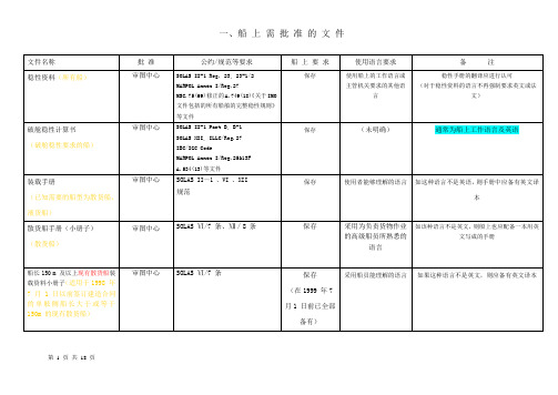
一、船上需批准的文件第 1 页共29 页第 2 页共29 页第 3 页共29 页第 4 页共29 页第 5 页共29 页第 6 页共29 页第7 页共29 页第8 页共29 页第9 页共29 页二、船上需验船师确认的文件第10 页共29 页第11 页共29 页第12 页共29 页三、船上张贴的其他文件和图第13 页共29 页第14 页共29 页第15 页共29 页第16 页共29 页四、保存在船上的其他记录、文件第17 页共29 页第18 页共29 页第19 页共29 页第20 页共29 页五、航海出版物、日志、记录簿、产品证书等第21 页共29 页第22 页共29 页第23 页共29 页第24 页共29 页六、船上应保存的图纸、文件资料(1)*(规范2007修改通报)(2007.4.1生效)第25 页共29 页第26 页共29 页六、船上应保存的图纸、文件资料(2)(规范2007修改通报UR Z23)(2008.1.1生效,建造合同)*提供:船上、船东/岸基管理部门、CCS(2008修改通报要求)第27 页共29 页*:1、2007.1.1及以后安放龙骨船,船上、岸基管理部门应保存上述(1)图纸第1~12项。
2、2007.4.1 及以后建造合同船,船上、船东和/或岸基管理部门还应保存上述(2)13~16项文件资料。
3、2008.1.1后检验(以检验工作控制号给出日期)的船舶,船上、岸基管理部门应保存的图纸文件资料应包括上述(1)和(2)的内容,――提前执行2008修改通报“新建船舶的船体检验(UR Z23)”部分。
第28 页共29 页4、2008.4.1 及以后建造合同船,(1)和(2)的图纸、文件资料,应提供CCS 归档。
5、上述(1)和(2)的内容部分重复;并与前面的有关手册内容重复。
第29 页共29 页。
4.船舶稳性
上海海事大学交通运输学院-刘红版权所有
15
上海海事大学交通运输学院-刘红版权所有
11
4.8. Inclining Experiment
倾斜试验的目的 试验方法及原理
上海海事大学交通运输学院-刘红版权所有
12
Байду номын сангаас
4.9. Stability at Large Angles of Inclination and Metacentric Stability 大倾角稳性与初稳性的比较 大角度倾斜时的回复力矩 静稳性曲线 稳性交叉曲线
Stable Equilibrium Neutral Equilibrium Unstable Equilibrium Conditions that Have Ship Initial Stability
上海海事大学交通运输学院-刘红版权所有 4
4.3.Initial Metacnetric Height and Initial Stability Formula
上海海事大学交通运输学院-刘红版权所有
10
2. The Effect of Loading and Unloading a Large Number of Cargos on Ship Floating and Stability
大量装卸(一般超过10%排水量): 大量装卸(一般超过 排水量) 排水量 步骤: 步骤:
上海海事大学交通运输学院-刘红版权所有 13
4.10. Dynamic Stability
动稳性与静稳性的区别 动稳性的衡量标准 静稳性曲线的应用 动稳性曲线 动稳性曲线与静稳性曲线的关系
上海海事大学交通运输学院-刘红版权所有 14
4.11. Criterion of Stability
船上应保存的文件资料
一、船上需批准的文件第 1 页共18 页第 2 页共18 页第 3 页共18 页第 4 页共18 页第 5 页共18 页第 6 页共18 页二、船上需验船师确认的文件第7 页共18 页第8 页共18 页三、船上张贴的其他文件和图第9 页共18 页第10 页共18 页第11 页共18 页四、保存在船上的其他记录、文件第12 页共18 页第13 页共18 页五、航海出版物、日志、记录簿、产品证书等第14 页共18 页第15 页共18 页第16 页共18 页六、船上应保存的图纸、文件资料(1)*(规范2007修改通报)(2007.4.1生效)第17 页共18 页六、船上应保存的图纸、文件资料(2)(规范2007修改通报UR Z23)(2008.1.1生效,建造合同)*提供:船上、船东/岸基管理部门、CCS(2008修改通报要求)*:1、2007.1.1及以后安放龙骨船,船上、岸基管理部门应保存上述(1)图纸第1~12项。
2、2007.4.1 及以后建造合同船,船上、船东和/或岸基管理部门还应保存上述(2)13~16项文件资料。
3、2008.1.1后检验(以检验工作控制号给出日期)的船舶,船上、岸基管理部门应保存的图纸文件资料应包括上述(1)和(2)的内容,――提前执行2008修改通报“新建船舶的船体检验(UR Z23)”部分。
4、2008.4.1 及以后建造合同船,(1)和(2)的图纸、文件资料,应提供CCS 归档。
5、上述(1)和(2)的内容部分重复;并与前面的有关手册内容重复。
第18 页共18 页。
IMO文件包括的所有船舶完整稳性规则-2008英文版
广
州
番
粤 禺
新
造
船
有
限
公
司
专
用
MSC 85/26/Add.1 ANNEX 2 Page 2 ANNEX INTERNATIONAL CODE ON INTACT STABILITY, 2008 (2008 IS CODE) CONTENTS PREAMBLE INTRODUCTION 1 Purpose 2 Definitions PART A – MANDATORY CRITERIA
广
州
番
粤 禺
Considerations for watertight and weathertight integrity Hatchways Machinery space openings Doors Cargo ports and other similar openings Sidescuttles, window scuppers, inlets and discharges Other deck openings Ventilators, air pipes and sounding devices Freeing ports Miscellaneous
Chapter 1 – General 1.1 Purpose 1.2 Application Chapter 2 – 2.1 2.2 2.3 2.4 2.5COMMENDATIONS FOR CERTAIN TYPES OF SHIPS AND ADDITIONAL GUIDELINES
imo文件包括的所有船舶完整稳性规则2008英文版道客巴巴
MSC 85/26/Add.1 ANNEX 2 RESOLUTION MSC.267(85) (adopted on 4 December 2008) ADOPTION OF THE INTERNATIONAL CODE ON INTACT STABILITY, 2008 (2008 IS CODE) THE MARITIME SAFETY COMMITTEE,
渔业船舶稳性校核及检查概述
第五篇稳性校核及检查第1章通则1.1 《规则》及本局同意的国际海事组织制定的现行船舶稳性标准是船舶稳性资料审查的依据。
各种渔业船舶适用的完整及破舱稳性标准见表1.1。
表1.1 稳性标准1.2 国际渔业船舶应按IMO稳性标准进行衡准。
非国际渔业船舶按《规则》规定的稳性标准衡准,也可按IMO稳性标准衡准。
第2章倾斜试验与空船排水量测量2.1 倾斜试验的目的在于确定空船排水量和重心的实际位置。
船舶应尽可能在接近完工状态(空船状态)下,进行倾斜试验。
如船舶限于条件,难以达到空船状态,可同意有不包括油、水在内的少量多余或不足物件。
多余或不足物件的重量一般应不超过空船排水量的0.5%。
2.2 新建船舶完工时,除另有规定者外,必须进行倾斜试验。
2.3 同一船厂按同一审批图纸建筑的同型船,除首制船外,可进行空船排水量测量以替代倾斜试验。
2.4 关于空船排水量占设计排水量75%以上的船舶,不管其是否为后续姐妹船,均应要求做倾斜试验。
2.5 后续姐妹船的空船排水量测量结果应与做倾斜试验的首制船进行比较,若其空船排水量与首制船相差超过2%,或重心纵向位置相差超过1%船长时,该船应重新进行倾斜试验。
2.6 若后续姐妹船的空船排水量及重心的纵向位置与首制船相差均不超过0.5%时,则首制船的完工稳性报告及装载手册可直接用于该船。
否则,用于完工稳性及装载手册的空船排水量及重心应依照倾斜试验及空船排水量测量结果进行偏于安全的计算后得出。
2.7 若后续姐妹船与首制船略有差不,且重量及重心相差已知,为便于按本篇2.5条的规定进行比较,应对首制船的重量重心进行调整计算以作为比较的基础。
2.8 如参考类似船舶的现有数据能明显地表示该船的尺度比例及布置,在一切可能的装载情况下均具有大于规定要求的初重稳距时,经验船部门同意,该船可免作倾斜试验。
2.9 倾斜试验应按本局同意的IMO RES.A·749(18)第7章“空船排水量和重心的确定”及其附录Ⅰ“倾斜试验实施指南”的要求进行。