减压控制阀设计说明书
减压控制阀的设计

*******学院毕业课题(设计)题目减压控制阀的设计指导教师院系班级学号姓名年月日摘要随着工业技术的不断发展,使得越来越多的机器设备使用上了高效的液压系统,在不同规格,不同型号,不同大小的液压设备里,我们都可以发现一个共同的控制元件—液压控制阀。
它的性能和寿命在很大程度上决定了液压系统的稳定性。
但是我发现仅仅是安装了液压控制阀还是完全不够的,有些机器还会发生机械元件过热,推进器失灵,没有过载保护而产生的机器毁坏。
而这些事故都是因为液压系统压力过大而产生的问题。
本文将着重研究减压控制阀的设计,并对减压阀结构进行探究。
意在不断优化减压阀的整体性能。
关键词:压力控制阀, 技术调节阀, 管式连接, 阀芯目录1引言 (1)1.1压力控制阀的介绍 (1)1.2减压控制阀的介绍 (1)1.2减压阀的运行机制 (2)1.4减压阀的生活作用 (2)2减压控制阀的设计 (3)2.1定比减压阀 (3)2.2减压阀研究优化设计 (5)2.3定差减压阀 (6)2.4导阀和主阀研究的重要性 (7)3 减压控制阀的导阀设计 (8)3.1主要结构尺寸确定 (9)3.2先导锥阀角2的选定 (11)3.3减压阀的定值输出方式 (12)4主阀弹簧的设计 (12)4.1弹簧外径的计算 (14)4.2弹簧曲度系数计算 (15)4.3弹簧的工作圈数 (16)5减压阀设计中有关注意事项 (17)6研究课题的优化设计 (18)6.1观点 (18)参考文献 (19)致谢 (20)第一章引言液压元件减压处理技术在功率密度、结构组成、响应速度、调速保护、过载保护、电液整台等方面都具有一定的优势,使其成为现代传动的重要技术手段和不可替代的关键基础技术之一,这些应用已经遍及了国民经济各个领域。
压力控制阀的介绍:压力控制阀是指用来对液压系统中液流的压力进行控制与调节的阀。
压力控制阀是控制和调节液流压力的阀的总称,简称压力阀。
它是采取使作用在阀芯上的液压力与阔芯弹簧力相平衡的方法,建立和维持被控液体的工作压力。
电子比例、直动减压 解压气缸阀门的产品说明说明书

Electro-proportional, direct-acting, pressure reducing/relieving valve with drain to port 4Capacity: 5 gpm (20L/min.)Functional Group:Products : Cartridges : Electro-Proportional : Reducing/Relieving : 4-Port, Direct Acting, Low Leakage, Externally Drained Model: PSDPProduct DescriptionThis electro-proportional, direct-acting reducer/reliever valve reduces a high primary pressure at the inlet (port2) to a constant reduced pressure at port 1, with a full flow relief function from port 1 to tank (port 3). Thevalve is biased to the relieving mode. Energizing the coil connects port 2 to port 1. Increasing the current tothe coil will proportionally increase the reduced pressure at port 1. If pressure at port 1 exceeds the settinginduced by the coil, pressure at port 1 is relieved to port 3. Draining port 4 makes the valve insensitive topressure at port 3. This valve is closed in the transition between reducing and relieving resulting in very lowconsumption of oil. Optional full manual control is available.Technical FeaturesMaximum pressure at port 3 should be limited to 3000 psi (210 bar). For optimum performance, an amplifier with current sensing andadjustable dither should be used. Dither should be adjustable between100 - 250 Hz.Full reverse flow from reduced pressure (port 1) to inlet (port 2) may cause the main spool to close. If reverse free flow is required in the circuit, consider adding a separate check valve to the circuit. Uses for the 'L and K' manual screw adjustment include: emergency valve setting during power failure or alternatively boosting the valve settingAll spring ranges are tested for correct operation with 5000 psi (350 bar) inlet pressure. With the 'L and K' adjustment screw, all ranges are factory set at zero (adjustment screw fully backed out). With the coil de-energized, clockwise adjustment of the screw will increase the spring bias load up to the maximum setting for that range. With the coil energized, any mechanical pressure setting is directly additive to the coil induced value.Suitable for accumulator circuits since the absence of pilot control flow results in reduced secondary circuit leakage. By controlling the pressure at the drain (port 4), the effective setting of the valve can be increased over the nominal valve setting.Direct acting concept provides highly reliable operation in contaminated systems, especially at dead headed conditions. Pressure on the drain (port 4) is directly additive to the valve setting at a 1:1 ratio and should not exceed 3000 psi (210 bar).Leakage specified in Technical Data is out of port 3 with a supply pressure of 2000 psi (140 bar) and the valve set at mid range. This leakage is directly proportional to pressure differential and inversely Incorporates the Sun floating style construction to minimize the possibility of internal parts binding due to excessive installation torqueand/or cavity/cartridge machining variations.Downloadproportional to viscosity expressed in centistokes.The transition from reducing to relieving is closed. The result is very low leakage. However, there is a transitional step increase in pressure between reducing and relieving modes. This step equals about 5% ofthe high end of the adjustment range, independent of the valve setting.PSDP-MDN-***Control Operating Range Seal Material CoilStandard OptionsL Standard Screw Adjustment M Manual Override (Standard) Standard OptionsB100 - 1200 psi (7 - 80 bar)D50 - 500 psi (3,5 - 35 bar)E25 - 250 psi (1,7 - 18 bar)Standard OptionsN Buna-NV Viton***See Coil Options BelowStandard Coil Options (View All)DIN 43650 3 pin(Hirschman)SAE J858A AMP Junior Timer Twin Lead Metri-Pack Deutsch DT04-2P *** no coil 612AMP Junior Timer 12 VDC 812Metri-Pack 12 VDC212DIN 43650 3 pin(Hirschman) 12 VDC624AMP Junior Timer 24 VDC 824Metri-Pack 24 VDC224DIN 43650 3 pin(Hirschman) 24 VDC712Twin Lead 12 VDC 912Deutsch DT04-2P 12 VDC524SAE J858A 24 VDC 724Twin Lead 24 VDC 924Deutsch DT04-2P 24 VDC Embedded Coil Options (Click Here)2B12A DIN 43650 3 pin(Hirschman) commandcommon on fourth pin 12VDC 0-20 mA 2C24V DIN 43650 3 pin(Hirschman) +5V referenceon fourth pin 24 VDC 0-10V4A12A Deutsch DT04-6P allfunctions enabled (separatecommand common, 5 vreference, and an enable) 12VDC 0-20 mA2B12V DIN 43650 3 pin(Hirschman) commandcommon on fourth pin 12VDC 0-10V 2D12A DIN 43650 3 pin(Hirschman) enable input onfourth pin 12 VDC 0-20 mA4A12V Deutsch DT04-6P allfunctions enabled (separatecommand common, 5 vreference, and an enable) 12VDC 0-10V2B24A DIN 43650 3 pin(Hirschman) commandcommon on fourth pin 24VDC 0-20 mA 2D12V DIN 43650 3 pin(Hirschman) enable input onfourth pin 12 VDC 0-10V4A24A Deutsch DT04-6P allfunctions enabled (separatecommand common, 5 vreference, and an enable) 24VDC 0-20 mA2B24V DIN 43650 3 pin(Hirschman) commandcommon on fourth pin 24VDC 0-10V 2D24A DIN 43650 3 pin(Hirschman) enable input onfourth pin 24 VDC 0-20 mA4A24V Deutsch DT04-6P allfunctions enabled (separatecommand common, 5 vreference, and an enable) 24VDC 0-10V2C12A DIN 43650 3 pin(Hirschman) +5V referenceon fourth pin 12 VDC 0-20mA 2D24V DIN 43650 3 pin(Hirschman) enable input onfourth pin 24 VDC 0-10V4F12V Deutsch DT04-6Pprogrammable ramps,separate rise and fall 12VDC 0-10V2C12V DIN 43650 3 pin(Hirschman) +5V referenceon fourth pin 12 VDC 0-10V 2F12V DIN 43650 3 pin(Hirschman) programmableramps, separate rise and fall12 VDC 0-10V4F24V Deutsch DT04-6Pprogrammable ramps,separate rise and fall 24VDC 0-10V2C24A DIN 43650 3 pin(Hirschman) +5V referenceon fourth pin 24 VDC 0-20mA 2F24V DIN 43650 3 pin(Hirschman) programmableramps, separate rise and fall24 VDC 0-10VAdditional Options (Click Here)Additional Coils512SAE J858A 12 VDCStainless options not available for this modelCopyright © 2002-2012 Sun Hydraulics Corporation. All rights reserved.Terms and Conditions - ISO Certification - Statement of Privacy。
阀门设计说明范文

阀门设计说明范文一、引言阀门是一种用于控制流体的机械装置,广泛应用于各种工业领域,包括石油、化工、电力、水处理、制药等。
阀门的设计和选择对流体的控制和安全起着关键作用。
本文将介绍阀门的设计要求、原则和流程。
二、设计要求1.流体参数:需要考虑的参数包括流量、压力、温度和介质性质。
2.使用环境:阀门的使用环境决定了其材料、密封和防护等要求。
3.控制要求:根据流体控制要求选择适当的阀门类型,如截止阀、调节阀、安全阀等。
4.安全要求:阀门在使用过程中应满足相关的安全标准,如阀座密封要求不漏气、阀杆不泄露等。
5.经济性:在设计阀门时要考虑成本和维护费用,平衡性能和经济之间的关系。
三、设计原则1.流体力学原理:根据流体力学原理确定阀门的结构形式、通径尺寸和流通方式。
2.密封原理:保证阀门的密封性能,采用合适的密封结构和材料,避免泄漏。
3.材料选择:根据介质性质和使用环境选择适合的材料,包括阀体、阀瓣、密封面等。
4.先进技术:借鉴和运用先进的技术,如CAD、CAM、仿真等,提高设计效率和质量。
5.标准符合:确保阀门设计符合国家和行业标准,如GB、API、ANSI 等。
6.可靠性和耐久性:确保阀门设计具有良好的可靠性和耐久性,减少故障和维护次数。
四、设计流程1.确定设计任务:明确阀门的使用条件、控制要求和安全标准。
2.设计方案选择:根据流体参数和使用环境选择合适的阀门类型和结构形式。
3.参数计算:根据流体力学、强度学和密封原理进行参数计算,包括通径尺寸、力矩、密封面压力等。
4.结构设计:进行阀门的结构设计,包括阀体外形、阀瓣形状、阀杆尺寸等。
5.材料选择:根据介质性质和使用环境选择适合的材料,进行密封面、阀座、阀杆等的材料选择。
6.CAD绘图:使用CAD软件进行绘图,生成三维模型,并进行结构优化和分析。
7.模型制造:根据CAD模型进行模型制造和装配,进行实际测试和性能验证。
8.试验验证:对阀门进行相关试验,如压力试验、密封试验、流量特性试验等。
Ruelco RV-1 压力解压阀说明书

OPERATIONThe Ruelco RV -1 Relief Valve is a stainless steel, soft seat, poppet relief valve capable of relieving pressures from 50 psi to 1,250 psi. The size of the valve makes it ideal for small spaces while the stainless steel construction allows the valve to operate in highly corrosive systems.FEATURES• 316 stainless steel construction • Externally adjustable• Wide adjustable ranges using only three springs • 100% tested •Compact designPHONE: 504-340-0055 FAX: 504-340-0056EMAIL:****************1209 DISTRIBUTORS ROW NEW ORLEANS, LA 70123DIMENSIONSSPECIFICATIONSFEMALE INLETPARTS LISTPHONE: 504-340-0055 FAX: 504-340-0056EMAIL:****************1209 DISTRIBUTORS ROW NEW ORLEANS, LA 70123ITEM QUANTITYDESCRIPTION MATERIAL 1 1 SPRING CAP 316 ST. STL. 2 1 LOCK NUT 316 ST. STL. 3 1 SPRING HOUSING 316 ST. STL. 4A 1 BLUE SPRING SPRING WIRE 4B - RED SPRING SPRING WIRE 4C - GOLD SPRING SPRING WIRE 5 1 SPRING PLATE 316 ST. STL. 6* 1 BODY SEAL NITRILE 7 1 RELIEF VALVE BODY316 ST. STL. 8 1 SEAL GUIDE 316 ST. STL. 9* 1 HEAD SEAL FLUROCARBON10 1 OUTER SLEEVE 316 ST. STL. 11* 1 PISTON SEAL NITRILE 121PISTON17-4 PH ST. STL* INDICATES ITEMS IN THE REPAIR KITREPAIR KIT•75-023-000OTHER TEMPERATURE RANGES AND SEAL COMPOUNDS AVAILABLE UPON REQUESTORDERING CODEOPERATIONThe Ruelco RV -1 Relief Valve is a stainless steel, soft seat, poppet relief valve capable of relieving pressures from 250 psi to 10,000 psi. The size of the valve makes it ideal for small spaces while the stainless steel construction allows the valve to operate in highly corrosive systems.FEATURES• 316 stainless steel construction • Externally adjustable• Wide adjustable ranges using only three springs •100% testedPHONE: 504-340-0055 FAX: 504-340-0056EMAIL:****************1209 DISTRIBUTORS ROW NEW ORLEANS, LA 70123DIMENSIONSSPECIFICATIONSFEMALE INLETPARTS LISTPHONE: 504-340-0055 FAX: 504-340-0056EMAIL:****************1209 DISTRIBUTORS ROW NEW ORLEANS, LA 70123ITEM QUANTITYDESCRIPTION MATERIAL 1 1 SPRING CAP 316 ST. STL. 2 1 LOCK NUT 316 ST. STL. 3 1 SPRING HOUSING 316 ST. STL. 4A 1 BLUE SPRING SPRING WIRE 4B - RED SPRING SPRING WIRE 4C - GOLD SPRING SPRING WIRE 5 1 SPRING PLATE 316 ST. STL. 6* 1 BODY SEAL NITRILE 7 1 RELIEF VALVE BODY316 ST. STL. 8 1 SEAL GUIDE 316 ST. STL. 9* 1 HEAD SEAL FLUROCARBON 10 1 OUTER SLEEVE316 ST. STL. 11* 1 PISTON SEAL NITRILE 121PISTON17-4 PH ST. STL* INDICATES ITEMS IN THE REPAIR KITREPAIR KIT•75-015-000OTHER TEMPERATURE RANGES AND SEAL COMPOUNDS AVAILABLE UPON REQUESTORDERING CODEOPERATIONThe Ruelco RV -1 Relief Valve is a stainless steel, soft seat, poppet relief valve capable of relieving pressures from 250 psi to 15,000 psi. The size of the valve makes it ideal for small spaces while the stainless steel construction allows the valve to operate in highly corrosive systems.FEATURES• 316 stainless steel construction • Externally adjustable• Wide adjustable ranges using only three springs •100% testedPHONE: 504-340-0055 FAX: 504-340-0056EMAIL:****************1209 DISTRIBUTORS ROW NEW ORLEANS, LA 70123DIMENSIONSSPECIFICATIONSPARTS LIST PHONE: 504-340-0055FAX: 504-340-0056 EMAIL:****************1209 DISTRIBUTORS ROW NEW ORLEANS, LA 70123ITEM QUANTITY DESCRIPTION MATERIAL 11SPRING CAP316 ST. STL.21LOCK NUT316 ST. STL.31SPRING HOUSING316 ST. STL.4A1BLUE SPRING SPRING WIRE 4B- RED SPRING SPRING WIRE 4C- GOLD SPRING SPRING WIRE 51SPRING PLATE316 ST. STL.6*1BODY SEAL NITRILE71RELIEF VALVE BODY17-4 PH ST. STL.81SEAL GUIDE316 ST. STL.9*1HEAD SEAL URETHANE 101OUTER SLEEVE316 ST. STL.11*1PISTON SEAL NITRILE121PISTON17-4 PH ST. STL * INDICATES ITEMS IN THE REPAIR KITREPAIR KIT• 75-034-000OTHER TEMPERATURE RANGES AND SEAL COMPOUNDS AVAILABLE UPON REQUEST ORDERING CODE。
霍尼韦尔(Honeywell)93-01 693-01组合压力减小与电磁阀闭合阀门说明书

Model No. 93-01/693-01COMBINATION PRESSURE REDUCING & SOLENOID SHUTOFF VALVE Sizes 1 1/4” - 24”FunctionThe Combination Pressure Reducing & Solenoid Shutoff Valve automatically reduces a higher inlet pressure to a steady lower downstream pressure regardless of changing flow rate and/or varying inlet pressure.“Tying” of equipment into packages for the purpose of thwarting competition shall be considered to be in non-compliance with these specifications. Manufacturers shall price items under different subsections or sections separately.Main ValveThe valve shall be hydraulically operated, single diaphragm-actuated, globe or angle pattern. The valve shall consist of three major components: the body with seat installed, the cover with bearings installed and the diaphragm assembly. The diaphragm assembly shall be the only moving part and shall form a sealed chamber in the upper portion of the valve, separating operating pressure from line pressure. Packing glands and/or stuffing boxes are not permitted and there shall be no pistons operating the main valve or pilot controls.Main Valve BodyNo separate chambers shall be allowed between the main valve cover and body. Valve body and cover shall be of cast material. Ductile Iron is standard, other materials shall be available. No fabrication or welding shall be used in the manufacturing process. Total shipping weight shall be equal or greater in all respects to the Hytrol 100-01/100-20 body.The valve shall contain a resilient, synthetic rubber disc, with a rectangular cross-section contained on three and one-half sides by a disc retainer and forming a tight seal against a single removable seat insert. No O-ring type discs (circular, square, or quad type) shall be permitted as the seating surface. The disc guide shall be of the contoured type to permit smooth transition of flow and shall hold the disc firmly in place. The disc retainer shall be of a sturdy one-piece design capable of withstanding opening and closing shocks. It must have straight edge sides and a radius at the top edge to prevent excessive diaphragm wear as the diaphragm flexes across this surface. No hourglass-shaped disc retainers shall be permitted and no V-type or slotted type disc guides shall be used.The diaphragm assembly containing a non-magnetic 303 stainless steel stem of sufficient diameter to withstand high hydraulic pressures shall be fully guided at both ends by a bearing in the valve cover and an integral bearing in the valve seat. The seat shall be a solid, one-piece design and shall have a minimum of a five-degree taper on the seating surface for a positive, drip-tight shut off.No center guides shall be permitted. The stem shall be drilled and tapped in the cover end to receive and affix such accessories as may be deemed necessary. The diaphragm assembly shall be the only moving part and shall form a sealed chamber in the upper portion of the valve, separating operating pressure from line pressure.The flexible, non-wicking, FDA approved diaphragm shall consist of nylon fabric bonded with synthetic rubber compatible with the operating fluid. The center hole for the main valve stem must be sealed by the vulcanized process or a rubber grommet sealing the center stem hole from the operating pressure. The diaphragm must withstand a Mullins Burst Test of a minimum of 600 psi per layer of nylon fabric and shall be cycle tested 100,000 times to insure longevity. The diaphragm shall not be used as the seating surface. The diaphragm shall be fully supported in the valve body and cover by machined surfaces which support no less than one-half of the total surface area of the diaphragm in either the fully opened or fullyclosed position.The main valve seat and the stem bearing in the valve cover shall be removable. The cover bearing and seat in 6” and smaller size valves shall be threaded into the cover and body. The valve seat in 8” and larger size valves shall be retained by flat head machine screws for ease of maintenance. The lower bearing of the valve stem shall be contained concentrically within the seat and shall be exposed to the flow on all sides to avoid deposits. To insure proper alignment of the valve stem, the valve body and cover shall be machined with a locating lip. No “pinned” covers to the valve body shall be permitted. Cover bearing, disc retainer, and seat shall be made of the same replacement of the main valve body shall be possible without removing the valve from the pipeline. Packing glands and/or stuffing boxes shall not be permitted and components including cast material shall be of North American manufacture.The valve manufacturer shall warrant the valve to be free of defects in material and workmanship for a period of three years accordance with all applicable instructions. Electrical components shall have a one year warranty.The valve manufacturer shall be able to supply a complete line of equipment from 1 1/4” through 24”sizes and a complete selection of complementary equipment. The valve manufacturer shall also provide a computerized cavitation chart which show flow rate, differential pressure, percentage of valve opening, Cv factor, system velocity and if there will be cavitation damage.Material SpecificationValve Size:Main Valve Body and Cover:Main Valve Trim:End Detail:Pressure Rating:Temperature Range:Rubber Material:Coating:Desired Options:Pilot Control SystemThe pressure reducing pilot control shall be a direct-acting, adjustable, spring-loaded, normally open, diaphragm valve designed to permit flow when controlled pressure is less than the spring setting. The pilot control is held open by the force of the compression on the spring above the diaphragm and it closes when the delivery pressure acting on the underside of the diaphragm exceeds the spring setting. The pilot control system shall include a fixed orifice. No variable orifices shall be permitted. The pilot system shall include an opening speed control on all valves 3” and smaller on the Model 93-01 and 4” and smaller on the model 693-01, as standard equipment.The pilot control shall have a second downstream sensing port which can be utilized to install a pressure gauge.The valve shall include a 3-way Nema IV Solenoid to intercept the pressure reducing control toclose/open the main valve. The solenoid shall have a warranty of 1 year.A full range of spring settings shall be available in ranges of 0 to 450 psi.A direct factory representative shall be made available for start-up service, inspection and necessaryadjustments.Material Specification for Pilot Control:Pressure Rating:Trim:Rubber Material:Tubing and Fittings:Adjustment Range:Operating Fluids:Desired Options:This valve shall be a Cla-Val Co. Model No. 93-01/693-01 Combination Pressure Reducing & SolenoidShutoff Valve as manufactured by Cla-Val Co., Newport Beach, CA92659-0325.。
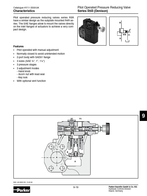
巴克兰公司的压力减压阀值系列R5R的说明说明书
H4
47.6
90
52.4
96
58.7
109
R5R06 ¾" SAE61 ¾" SAE61
9-23
L1
L2
24.6
22.2
26.5
26.2
34.0
30.2
Port size R5R08
1" SAE61 1" SAE61
G¼" G¼"
L3
d1
d2
152
19
10.5
171
25
10.5
179
32
12.5
R5R10 1¼" SAE61 1¼" SAE61
5
0
50
Minimum pressure curve
100
150
Flow Q [l/min]
9 Reduced pressure pA versus flow Q Series R5R10 1)
1) Measured at 350 bar primary pressure pB.
R5R_UK.INDD RH_13.03.08
Pressure stages Nominal flow Fluid Fluid temperature Viscosity permitted Viscosity recommended Filtration Electrical (solenoid) Duty ratio Solenoid connection Protection class
9
NG
B1
H1
H2
06
60
131.6
37
08
可调式减压阀说明书

Y X 741X-可调式减压阀使 用 说 明 书株洲南方阀门股份有限公司一、用途10 1625 40安装在供水管网上,将较高的上游压力降为符合使用要求的下游工作压力。
无论上游压力和流量如何改变,预定的下游压力都能保持恒定不变。
二、特点1、减压稳压效果好。
外设独立的压力反馈系统,利用液压原理进行控制。
出口压力不受进口压力及流量变化的影响,既可减动压,又可减静压。
2、操作维护方便。
只需调节先导阀的调节螺栓,就能获得精确稳定的出口压力,关键零件均采用优质材料,基本无需维护。
3、过流面积大,阻力损失小。
采用流线型、宽阀体设计。
4、在压力降低较大的场所下,可采用特殊阀板设计,减少噪声和振动。
三、技术参数1、公称压力:1.0MPa 1.6MPa 2.5MPa 4.0MPa2、出口压力:PN1.0MPa调节范围0.1~0.8MpaPN1.6MPa调节范围0.2~1.4MpaPN2.5MPa调节范围0.3~2.0MpaPN4.0MPa调节范围1.0~3.5Mpa3、适用介质:清水4、适用温度:0~80℃四、结构示意图减压阀是由主阀和导阀控制系统组成。
主阀由阀体、膜片、阀杆、阀板等主要零件组成;导阀控制系统由闸阀、减压导阀、过滤器、压力表、调节阀、附管组成。
图一结构原理图1、闸阀2、过滤器3、先导阀4、压力表五、工作原理可调式减压阀是通过出口压力的变化反馈到导阀上,再由导阀来控制主阀板的开度,使预定的下游压力保持不变。
当出口压力大于导阀的设定值时,出口压力水从控制管进入导阀膜片下腔内,推动导阀阀杆上移,导阀阀板开度减小,从而导致从控制管进入导阀再到主阀控制室上腔的压力水的压力升高,推动阀杆下移,主阀板的开度随之减小,阀后压力降低。
当出口压力小于导阀的设定值时,导阀膜片下腔的压力降低,导阀阀杆下移,其阀板开度增大,进口压力水从控制管进入导阀再到出口端,使主阀上腔压力降低,主阀板的开度随之增大,阀后压力增高。
六、安装注意事项1、安装前需冲洗管道。
自力式减压阀说明书
ZZYP型自力式减压阀运行维护手册ZZYP型自力式减压阀一、用途与特点ZZYP型自力式减压阀(简称调压阀)是利用被调介质自身能量实现自动调节的执行器产品。
该产品最大特点,能在无电、无气的场所工作,是一种节能产品。
压力设定值可在运行中随意调整。
常规产品采用快开流量特性,亦可采用线性、等百分比流量特性。
动作灵敏,减压比一般情况下最大可达10,最小为1.25,广泛应用于石油、化工、电力、冶金、食品、轻纺、居民楼群等各种工业设备中的气体、液体、蒸汽等介质低压差减压、稳压(用于控制阀后压力),或泄压、稳压(用于控制阀前压力)的自动控制。
二、结构与原理1、结构(图1)调压阀主要由执行机构、调节机构、导压管与接管等四部分组成。
执行机构有薄膜式(用于被调压力≤0.6Mpa)、活塞式(用于被调压力>0.6Mpa)、波纹管式(用于高温或腐蚀性流体),调节机构为单座(波纹管平衡)型式(控制压力≤1.0MPa)。
产品外形图图12、原理(图2)图2a结构为单座式,阀后压力控制,初始状态常开。
原理:介质由箭头方向进入阀体,经阀芯、阀座节流后输出。
另一路经冷凝器(介质为蒸汽时使用)冷却后,引入执行机构膜室,其压力作用在膜片有效面积上产生一个推力,带动阀杆、阀芯位移,使节流口面积发生变化,达到减压稳压目的。
若阀后压力高于设定值,则作用在膜片上的力增大,压缩弹簧,带动阀芯位移,减小调压阀开度,直至阀后压力下降到设定值。
同理,若阀后压力低于设定值,由于弹簧反作用力,带动阀芯位移,增大调压阀开度,直至阀后压力上升到设定值图2b结构为单座式,阀前压力控制,初始状态常闭。
原理:介质由箭头方向进入阀体,另一路经冷凝器(介质为蒸汽时使用)冷却后,引入执行机构膜室,其压力作用在膜片有效面积上产生一个推力,带动阀杆、阀芯位移,使阀门开启度增大,若阀前压力高于设定值,则作用在膜片上的力增大,压缩弹簧,带动阀芯位移,增大调压阀开度,直至阀前压力下降到设定值。
- 1、下载文档前请自行甄别文档内容的完整性,平台不提供额外的编辑、内容补充、找答案等附加服务。
- 2、"仅部分预览"的文档,不可在线预览部分如存在完整性等问题,可反馈申请退款(可完整预览的文档不适用该条件!)。
- 3、如文档侵犯您的权益,请联系客服反馈,我们会尽快为您处理(人工客服工作时间:9:00-18:30)。
毕业设计(论文)说明书题目:减压控制阀的设计系名机械工程系专业机械设计制造及其自动化学号6012201230学生姓名周翔指导教师朱家玲2016年5月20日摘要随着工业技术的发展,液压系统在当今机械领域用途越来越广泛,各种大、中、小型液压设备中,液压减压阀是系统中的一个关键性的压力控制元件,它们的性能和寿命在很大程度上决定着整个液压系统的平稳性和工作能力。
设计中对减压阀结构进行了探讨,并且比较了两种方案的优劣特点,选择了管式螺纹连接定值输出减压阀。
在现有的减压阀基础上通过改变主阀芯的材料,从而提高减压阀的灵敏度,使产品在满足设计条件要求的情况下,更加经济合理化。
在这次毕业设计中主要参考了DR50型先导式减压阀的相关产品的结构和技术参数,并以其为基础,重新设计了先导式定值输出液压减压阀阀芯的结构参数,通过计算和不断优化使减压阀的部分或整体性能有所提高完善。
关键词:先导式减压阀;管式连接;阀芯结构参数AbstractAlong with the development of the technology industry, Hydraulic system in tod- ay's machinery field use more and more widely, In all the big or small hydraulic equi- pment, Hydraulic pressure reducing valve is system of a key pressure control compo- nents.This design mainly in the market today of the pressure reducing valve for the fo- undation, Pilot type setting value output pressure reducing valve design. In the gradu- ation design process adopted some of the pressure reducing valve about new technolo- gy and new ideas, And used topilot type setting value output pressure reducing valve design, In the design of pressure reducing valve structure were discussed.In the graduation design main reference the forerunner of the pressure reducing valve DR50 type of related products structure and technical parameters, And as the f- oundation, To guide the design of hydraulic pressure reducing valve setting value ou- tput valve core structure parameters, Through calculation and continuous optimization of the pressure reducing valve to part or whole performance improved perfect.Key words:Pilot Operated Reducing Valves;Tube Type Conjunction;The Valve Core Structure Parameters目录第一章引言 (1)第二章减压阀 (3)2.1 减压阀的简介 (3)2.2 定值减压阀 (3)2.3 定比减压阀 (5)2.4 定差减压阀 (6)2.5 我国引进的德国力士乐公司压力阀系列 (7)第三章设计方案的分析与选定 (9)3.1 设计的目的及范围 (9)3.2 设计的任务要求 (9)3.3 设计的总体思路 (9)3.4 设计方案的对比与确定 (10)第四章减压阀的结构设计及计算 (12)4.1 减压阀的设计内容 (12)4.2 减压阀的设计步骤 (12)4.2.1 主要结构尺寸的初步确定 (12)4.2.2 主阀弹簧的设计 (14)4.2.3 先导阀弹簧的设计计算 (17)第五章减压阀结构材料的选择及回油路的设计205.1 减压阀主要构件的材料选择 (20)5.1.1 阀体(壳体)的材料选择 (20)5.1.2 阀芯与阀套的材料选择 (20)5.1.3 先导式减压阀的远程控制口K的用途 (20)5.1.4 液压阀主要构件加工工艺 (20)5.2 减压阀回油路的设计 (21)5.2.1 减压回路的工作原理 (21)5.2.2 减压阀设计应该注意事项 (22)5.2.3 减压阀常见的故障及诊断排除 (22)第六章减压阀的性能指标及造型 (25)6.1 减压阀的主要静态性能指标 (25)6.2 减压阀的动态性能 (26)6.3 减压阀的设计造型图 (27)第七章结论 (29)参考文献 (30)外文资料中文译文致谢第一章引言液压技术在功率密度、结构组成、响应速度、调速保护、过载保护、电液整台等方面都具有一定的优势,使其成为现代传动的重要技术手段和不可替代的关键基础技术之一,这些应用已经遍及了国民经济各个领域。
我国的液压工业兴起于第一个五年计划(1953~1957年),由于机床制造工业发展的迫切需求,50年代初期,上海机床厂、天津液压件厂仿造了苏联的各类低压泵、阀。
随后,以广州机床研究所为主的工厂,在引进消化国外中低压元件制造技术的基础上,自主创新了2.5MPa和6.3MPa公称压力的中低压液压阀系统(简称广州型),并迅速投入到生产当中。
到了60年代初期,为了让液压工程机械从中低压向高压方向得到稳定发展,以山西榆次液压件厂为主的工厂,引进了日本油研公司的21MPa公称压力的中高压系列的液压阀。
1977年,正式完成了公称压力为31.MPa的新系列高压阀的设计。
建国以来,我国在液压行业及制造生产液压阀方面,从无到有取得了较好的成绩。
经过几十年的发展,减压阀的种类各式各样,非常全面,液压阀方面的国家标准也很完善了,针对减压阀的技术参数已形成了系列化,标准化。
至此之后,液压阀的发展奠定了良好的基础。
近些年的液压阀技术和生产呈现出百花齐放的趋势。
这也为行业的发展提供了良好的条件,早期、中期的技术引进,现阶段液压阀的技术发展不断向技术创新方面转型。
与国际技术先进厂家的合作之后,尽管在液压阀方面有了长足的进步,但是国内的技术力量和生产水平与国外同类产品的比较中,品种以及性能指标依然有差距。
国外液压阀的生产设计兴起较早,并且经过了长期的技术积累并不断的取得技术进步,国外的液压阀技术已形成了强大、优秀的发展体系,液压设备能传达很大的力与力矩,单位功率重量轻,结构尺寸小,在同等功率下,反应速度快、准、稳;大范围内能够简单的实现无级变速的功能;容易放大功率;方便避免过载;使其更加润滑,寿命更长,制造成本更低。
所以,世界各国均将液压阀应用在机械设备、施工机械、机械工业、汽车工业、金属矿物工业、农业机械、船舶交通、铁道、飞机、坦克、导弹、火箭、雷达等国防工业中。
不管液压系统有多么的简单,液压阀都不可取代;同一工艺目的的液压机械设备,不同的多种液压系统方案都是由液压阀的不同组成和使用而形成的,所以液压技术中品种与规格最多、应用最广泛、最活跃的元件是液压阀;作为液压阀一种的减压阀在液压系统中起着关键的作用。
液压系统设计的是否合理、安装维护的是否便利以及能否按照要求正常运行,所采用的各种液压阀的性能优劣及其参数匹配是否合理都是其正常运行的关键因素。
减压阀的功能主要是通过调节,将进口压力减至某一需要的出口压力,凭借着其介质本身的能量,使出口压力自动保持阀门的稳定性,这些都属于压力控制阀的类型。
液压系统中,使用最多的减压阀主要有定值输出减压阀、定差减压阀和定比减压阀。
在近代液压技术发展过程中,定值输出减压阀实用的更为广泛。
与定差减压阀、定比减压阀相比,定值输出减压阀的优点体现在结构简单、尺寸小、重量轻、流量均匀、噪声低等方面。
在各类液压阀中,定值输出减压阀的二次压力(出口压力)是恒定值,这个是它的主要功能,具有匀速平稳进给运动的液压系统可以保持输出油路压力恒定,所以必须使用减压阀。
减压阀是液压系统中的一类关键控制元件。
本课题基于现有减压阀的制造与设计技术,针对本次毕业设计要求的大压强、大流量进行设计,从设计的角度来说,应该注意解决现有减压阀存在的一些问题,还需要对减压阀阀芯进行改造。
并运用三维软件对设计的减压阀进行建模。
通过设计造型以实现用途与外观的完美结合。
第二章减压阀2.1 减压阀的简介减压阀是能够将出口压力调节到低于进口压力的控制阀。
减压阀可以减低系统中任一分支液压油路的压力,用来满足液压设备执行元件的需要,常见于各种液压控制系统、夹紧系统、辅助系统及润滑系统中。
按调节要求的不同其可以分为定值减压阀、定比减压阀和定差减压阀。
定压减压阀控制出口压力为定值,使液压系统中某一部分比供油压力更低的稳定压力;定比减压阀可以控制它的进、出口压力保持恒定的比例;定差减压阀可以控制进、出口压力差为恒定的大小。
2.2 定值减压阀定值减压阀的结构和工作原理:定压输出减压阀分为直动式和先导式两种结构形式,直动式减压阀很少拿来单独的使用。
在先导式减压阀中,由于先导级供油引入方式的异同,有先导级减压出口供油和减压进口供油两种结构形式。
图2-1 工作原理图工作原理如图2-1:进口压力P1经减压口减压后压力变为出口压力P2,出口压力油经主阀体上的通道6和底座8上的通道进入主阀芯9的下腔,再经过主阀芯上的阻尼孔进入主阀芯的上腔和先导阀的前腔,然后再通过锥阀座4中的阻尼孔后,作用到先导锥阀3上。
当出口压力低于调定压力时,先导阀口关闭,主阀芯下端的阻尼孔中没有油液流动,主阀芯上、下两端的油压力相等,主阀芯在弹簧力的作用下处于最下端位置,减压口全开,不起减压作用,即P 1≈P 2。
当出口压力超过调定压力时,出油口部分液体经过阀座上的通道、主阀芯阻尼孔、主阀腔、先导阀口、先导阀上的泄漏油口L 流回油箱。
阻尼孔有油液通过,产生压力损失,使主阀芯上下腔产生压力(P 2>P 1),此压力差所产生的作用力大于主阀弹簧力时,主阀上移,使节流口(减压口)关小,减压作用增强,直到主阀芯稳定到某一平衡位置,此时出口压力P 2取决于先导阀弹簧所调定的压力值。