TK-3217(C)
fleetsync信令使用方法

状态信息呼叫
可以预先存储50个状态代码,用 编码器选择发出。当收到代码时, 显示预先设置对应的字符。
10 START
101-1001
101-1002
不用讲话,只要默契,意思就可 以清晰的表达了。对会场内 外的沟通可以有帮助吧。
.
个别选呼
虽然没有键盘,但可以预先存 储100个呼叫ID。通过选择不同 的呼叫ID,可以实现个别选呼, 而无需按键拨号。
.
语音加密功能
101-1001
101-1002
把钱取回来!!
把钱取回来!
(已加密)
(已加密) 101-1003
(未加密)
“噜噜…”
这说的是什么呀?
.
电池电量显示
显示屏
是否想了解电池消耗 情况,如果不防备, 在重要的通话过程中, 电量突然不够了,可 够着急的了。
.
电池电量显示
显示屏
我的大显示屏上有专 门的电池电量显示, 你可以随时观察它, 该换电池时候就要及 时更换。
.
电池电量显示
显示屏
注意:当使用建伍
公司生产的KNB-29N的 时候,电量显示准确度 最高。使用其他电池时 会有误差,仅供参考噢。
.
声控发射.免提电话
两手在做别的工作,又要 和对方讲话,碰这种时候 可能还不少呢. 例如: 开车的时候. 操作计算机的时候. 怎么办?
.
声控发射.免提电话
利用我内置的声控发射 功能,就可以完成这样 的操作.免提通话可以 解放双手,方便吧! 如果要用耳机,使用普 通音道耳机/送话器就 可以了.便宜不少呢!
.
如果有这方面的问题或要 求,我内置的 FleetSync/FleetSyncⅡ的 信令体系可以帮助您,试 试吗?
KOYO ELECTRONICS INDUSTRIES CO., LTD. GC7系列可编程触摸面板

352Visit our websitehttp://www.koyoele.co.jp/english/KOYO ELECTRONICS INDUSTRIES CO., LTD.GENERAL CATALOG 2014Latest catalog (free) is available online.Visual ScopeGC7FeaturesProgrammable Touch Panel (GC Type)Inherited the GC-5 display.- 10.4-inch TFT color Model number: GC-76LC - 5.7-inch STN color Model number: GC-73LCL-R- 5.7-inch STN monochrome Model number: GC-73LM-RFeatures- Shifted from the GC50 series.The applications of the GC-50 series (GC-53LC3, GC-53LM3, and sGC-56LC2) are partially inherited.The applications can be replaced within restrictions.Restrictions from the GC50 Series1. Drawing softwarePrepare ScreenCreator5 Ver3.0 or later.You can download the drawing software from Koyo Electronics' websitefree of charge.2. Panel cutout dimensionsThe panel cutout dimensions are not changed.The display can be installed in the existing holes for attaching the controlpanel as is.3. DimensionsThe 5.7-inch type is 7.1 mm thicker in depth. The 0.4-inch type is 3.0 mm wider in width.Since the location and size of mounting brackets and external connectionconnectors are different, make sure that there are no interfering parts inside and outside the board.4. Power SupplyThe 5.7-inch type is connected to the main body, not by terminal blockbut by connector (bundled item). The 10.4-inch type has been changed to 24 V DC speci cation.If you use the GC7 at 100 V/200 V AC, use the optional EA-AC orprepare a commercial AC/DC power supply. (If the EA-AC is used, the depth of the product becomes the main body + 36.1 mm.)5. Con firmation of PLC modelsPLCs that can be used are largely limited. Also, the shapes of connectionconnectors are different. (M:N communications also cannot be used.)6. Con firmation of peripheral devicesThe GC70 series has only one serial port.Also note that there are no parallel ports or RAS output / reset input.- ScreenCreator5 is usable.The ScreenCreator5 drawing software has been upgraded. You can draw in the same way as with the GC-50 series.7. Touch panel operationSince an analog-type touch panel is used, there are the following restrictions.- You cannot press two, three, or four points at the same time. - The resolution of the touch panel is different.Since the GC50 series has a different resolution (16 x 12 or 32 x 24) from the GC70 series (1,024 x 1,024), the operational feeling may be different.8. When K-BASIC is usedThere are restrictions on usable instruction words.9. When option products are usedThe digital I/O cannot be used.The backup data in a CF card is not compatible. If the data is backed up by a CF card for the GC50 series, restore the screen data to ScreenCreator5 once. Each setting data needs to be reset for the GC70 series.10.How to download screen dataScreen data can be transferred via USB.11.OtherThere may be restrictions in addition to the items mentioned above.Viewing angle of the screen, appearance of reduced / enlarged characters, appearance of the black-and-white type (difference between blue type LCD and black-and-white mode), etc.* When you change models, it is recommended that you check the operations using actual equipment once.353KOYO ELECTRONICS INDUSTRIES CO., LTD.GENERAL CATALOG 2014The specifications and prices described in this catalog were valid when the catalog was issued.For the latest information, contact our sales persons or see our website.Visual Scope GC7SpecificationsHow to Transfer SoftwareRead the screen data project using ScreenCreator5 (Ver3.0 or later).Change the target panel to the new model (GC-73LM-R / GC-73LCL-R / GC-76LC) using ScreenCreator5 (Ver3.0 or later).Recompile the screen data using ScreenCreator5 (Ver3.0 or later).Download the compilation data to the new model using ScreenCreator5 (Ver3.0 or later).* In a new model, it is not necessary to change to the download mode at hardware side like previous models.If the computer and the display are connected via a USB cable and the data is downloaded from a computer, the display automatically changes to the download mode and automatically restarts after the completion of the download.Each Part Names and Descriptions1 Power supply (24 V DC) Can be used for the power supply in the same conditions as GC-53L 3.2 CF card slotThe screen data can be uploaded/downloaded from a CF card.3 AC power supply module (Option) Can be used with a power supply under the same conditions as the GC-56LC2.4 Various LEDs You can check the power supply / status / transmission and reception.5 Battery Retain clock data / SRAM.6 Serial port For connection to a PLC7 USB A port The screen data can be uploaded/downloaded from a USB memory. 8 USB B port The screen data can be uploaded/downloaded from drawing software.Cable length: 3 mNot in Use4 Various LEDs3 AC Power Supply Module (Option)7 USB A Port8 USB B Port5 Battery6 Serial Port2 CF Card Slot 1StandardExpansion (Option is installed)354Visit our websitehttp://www.koyoele.co.jp/english/KOYO ELECTRONICS INDUSTRIES CO., LTD.GENERAL CATALOG 2014Latest catalog (free) is available online.Visual Scope GC7Specifications*1 Since this display uses a cold-cathode tube for the backlight, the brightness widely uctuates according to the conditions shown below. Consider the described brightness as a target. Ambient temperature, installation angle of the product, elapsed time since power-on, duration of use of the product, and number of product power supply ON/OFF cycles *2 Only the speci c card can be used.* Regarding the EA-AC speci cations, see P.349.355KOYO ELECTRONICS INDUSTRIES CO., LTD.GENERAL CATALOG 2014The specifications and prices described in this catalog were valid when the catalog was issued.For the latest information, contact our sales persons or see our website.Visual Scope GC7SpecificationsSupported PLCs as of May 2012Largely restricted compared with the GC50 series.If devices other than those above are connected, it is impossible to shift to the GC70 series.356Visit our websitehttp://www.koyoele.co.jp/english/KOYO ELECTRONICS INDUSTRIES CO., LTD.GENERAL CATALOG 2014Latest catalog (free) is available online.Visual ScopeHole12.1inch15.0inch357KOYO ELECTRONICS INDUSTRIES CO., LTD.GENERAL CATALOG 2014The specifications and prices described in this catalog were valid when the catalog was issued.For the latest information, contact our sales persons or see our website.Visual Scope GC7Correlation。
超米特电子有限公司产品说明书

1US Headquarters TEL +(1) 781-935-4850FAX +(1) 781-933-4318 • Europe TEL +(44) 1628 404000FAX +(44) 1628 404090Asia Pacific TEL +(852) 2 428 8008FAX +(852) 2 423 8253South America TEL +(55) 11 3917 1099FAX +(55) 11 3917 0817Superior elongation and tensilestrength help to prevent tearing in use due to mishandling. Typical properties for CHO-SEAL 1310 and 1273 materi-al are shown on pages 33 and 32respectively.High Shielding PerformanceCHO-SEAL 1310 material provides more than 80 dB of shielding effectiv-ness from 100 MHz to 10 GHz, while CHO-SEAL 1273 material provides more than 100 dB.Low Volume ResistivityBoth materials have exceptionally low volume resistivity, which makes them well suited for grounding appli-cations in which a flexible electrical contact is needed.Low Compression GasketSpacer gaskets are typicallydesigned to function under low deflec-tion forces. Chomerics uses design tools such as Finite Element Analysis (FEA) to accurately predict compres-sion-deflection behavior of various cross section options. Refer to page16.LCP Plastic SpacerLiquid crystal polymer (LCP)spacers, including those made with Vectra A130 material, provide aCHO-SEAL ®1310 or 1273Conductive ElastomersWith EMI spacer gaskets, shielding and grounding are provided by Chomerics’CHO-SEAL 1310 and 1273 conductive elastomers, specifi-cally formulated for custom shape molded parts. They provide excellent shielding and isolation against electro-magnetic interference (EMI), or act as a low impedance ground path between PCB traces and shielding media. Physically tough, these elas-tomers minimize the risk of gasket damage, in contrast to thin-walled extrusions or unsupported molded gaskets.Silicone-based CHO-SEAL 1310and 1273 materials offer excellent resistance to compression set over a wide temperature range, resulting in years of continuous service. CHO-SEAL 1310 material is filled with silver-plated-glass particles, while 1273 utilizes silver-plated-copper filler to provide higher levels of EMI shielding effectiveness.EMI Spacer GasketsThe unique design of Chomerics’EMI spacer gaskets features a thin plastic retainer frame onto which a conductive elastomer is molded. The elastomer can be located inside or outside the retainer frame, as well as on its top and bottom surface. EMI spacer gaskets provide a newapproach to designing EMI gaskets into handheld electronics such as dig-ital cellular phones. Board-to-board spacing is custom designed to fit broad application needs. Customized cross sections and spacer shapes allow for very low closure forcerequirements and a perfect fit in any design or device.Robotic InstallationSpacer gaskets can be installed quickly by robotic application. Integral locater pins in the plastic spacer help ensure accuratepositioning in both manual and pick-and-place assembly. Benefits include faster assembly and lower labor costs.The integrated conductive elastomer/plastic spacer gasket is a low cost,easily installed system for providing EMI shielding and grounding in small electronic enclosures.Figure 1Single Piece EMI Gasket/Locator PinsCHO-SEAL 1310 or 1273 Conductive Elastomer (Inside)Plastic Spacer Around Outsideor InsideApplications for EMI Spacer GasketsThe spacer gasket concept is especially suited to digital and dual board telephone handsets or other handheld electronic devices. It provides a low impedance path between peripheral ground traces on printed circuit boards and components such as:•the conductive coating on a plastic housing•another printed circuit board •the keypad assemblyTypical applications for EMI spacer gaskets include:•Digital cellular, handyphone and personal communications services (PCS) handsets •PCMCIA cards•Global Positioning Systems (GPS)•Radio receivers•Other handheld electronics, e.g.,personal digital assistants (PDAs)•Replacements for metal EMI shield-ing “fences” on printedcircuit boards in wireless tele-communications devicesstable platform for direct, highprecision molding of conductive elas-tomers. The Vectra A130 material described in Table 1 has excellent heat deflection temperature character-istics (489°F, 254°C). For weight con-siderations, the LCP has aspecific gravity of only 1.61. This plas-tic is also 100% recyclable.Typical EMI Spacer Gasket Design ParametersThe EMI spacer gasket concept can be considered using the design parameters shown in Table 2. Some typical spacer gasket profiles are shown below.Figure 2Typical Spacer Gasket Profiles3US Headquarters TEL +(1) 781-935-4850FAX +(1) 781-933-4318 • Europe TEL +(44) 1628 404000FAX +(44) 1628 404090Asia Pacific TEL +(852) 2 428 8008FAX +(852) 2 423 8253South America TEL +(55) 11 3917 1099FAX +(55) 11 3917 0817Finite Element AnalysisChomerics, a division of the Parker Hannifin Corporation’s Seal Group, is the headquarters of Parker Seal’s Elastomer Simulation Group. This unit specializes in elastomer finite element analysis (FEA) using MARC K6 series software as a foundation for FEA capability.Benefits of FEA include:•Quickly optimizing elastomer gasket designs•Allowing accurate predictions of alternate elastomer design concepts •Eliminating extensive trial and error prototype evaluationTypical use of FEA in EMI spacer gasket designs is to evaluate the force vs. deflection requirements of alternate designs.For example, onespacer design features a continuous bead of con-ductive elastomer molded onto a plastic spacer. An alternative designemploys an “interrupted bead,” where the interrup-tions (gaps left on the plastic frame) are sized to maintain the requiredlevel of EMI shielding. Figure 4illustrates these alternative designs.Gasket DeflectionFigure 5 compares the effect of continuous and interrupted elastomer gasket designs in terms of the force required to deflect the conductive elastomer. This actual cellular handset application required a spacer gasket with interrupted bead to meet desired deflection forces.Chomerics Designand Application ServicesChomerics will custom design a spacer for your application. Advice,analysis and design assistance will be provided by Chomerics Applications and Design engineers at no additional fee. Contact Chomerics directlyat the locations listed at the bottom of the page.Figure 3FEA Example of an EMISpacer Gasket Cross SectionFigure 4Continuous (top) and InterruptedElastomer GasketsFigure 5Typical Spacer Gasket Deflection。
西门子安全继电器3TK2807
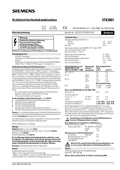
Betrieb nur im Einbauraum mit IP 54 zulässig (z. B. Schaltschrank)!-NOT-AUS-Schaltungen-Schaltungen zur Überwachung von Schutzeinrichtungen (z.B. Schutz-gittern)-Schaltungen, bei denen gesteuertes Stillsetzen gemäß DIN EN 60204-1, VDE 0113 Teil 1: (1998-11) STOP-Kategorie 1 erforderlich ist.Bei Geräten, deren Netzspannung gleich der Steuerspannung ist, ist unbedingt die DIN EN 60204-1, VDE 0113 Teil 1: (1998-11), Punkt 9.1.1 zu beachten!Die interne Steuerung der Schützsicherheitskombination ist nach DIN EN 60204-1, VDE 0113 Teil 1: (1998-11), Absatz 9.4.2.2 ausgeführt, so dass im Falle eines Fehlers in einem Hilfsschütz die Funktion des Sicherheitsstrom-kreises erhalten bleibt. Die Versorgungsspannung muss den Anforderungen der DIN EN 60204-1, VDE 0113 Teil 1: (1998-11) entsprechen (der Anschluss “A2“ muss an die mit dem Schutzleitersystem verbundene Seite des Steuerstromkreises angeschlossen werden). Bei jedem EIN- und AUS-Zyklus der zu schaltenden Maschine werden die Schaltglieder der Hilfs-schütze auf korrektes Öffnen und Schließen überprüft. Dies geschieht z.B. durch:-Ab- und Zuschalten der Steuerspannung durch den Hauptschalter -Betätigen und Entriegeln der NOT-AUS-Einrichtung -Öffnen und Schließen des Schutzgitters.Geräteschaltpläne und Anschlussbeispiele , siehe Bild III :a Innenschaltbild (DC-Ansteuerung), Prinzipdarstellung b Schutztür-Schaltung (2kanalig)c NOT-AUS-Schaltung (2kanalig)d Schutztür-Schaltung (2kanalig)Automatischer Anlauf mit zwangsöffnenden Schaltern.e NOT-AUS-Schaltung (2kanalig mit einem Zusatzbaustein 3TK29...).Hinweis: Eine 1kanalige Ansteuerung der Schützsicherheitskombination ist realisierbar, indem man die Schutzeinrichtung zwischen den Anschluss X1 und den verbundenen Anschlüssen X3; X5 schaltet.Die außenliegende Ansteuerung ist beispielhaft, sie muss durch eine Risi-kobewertung durch den Anwender festgelegt werden.Weitere Applikationen auf Anfrage.Maßbilder (Maße in mm), siehe Bild I .Seitlicher Mindestabstand zu geerdeten Teilen: 3 mm (siehe Bild IIa ).Anschluss, siehe Bild IIb .Plombierabdeckung, siehe Bild IIc .Bei der Montage Schützsicherheitskombination abdecken, wenn Fremdkörper (z.B. Bohrspäne) auf die Geräte gelangen können. Bei Verschmutzungsgefahr, starkem Staubanfall oder aggressiver Atmo-sphäre Schützsicherheitskombination in Gehäuse einbauen.Reinigung: Staubablagerungen entfernen (absaugen!).Die Betriebszustände des Gerätes:“NETZ“ zeigt an, dass das Gerät an Spannung liegt.“KANAL 1“ und “KANAL 2“ leuchten, wenn der EIN-Taster betätigt wurde und die NOT-AUS- bzw. Schutztüreinrichtung geschlossen ist.Warnung:Gefährliche elektrische Spannung!Kann zu elektrischem Schlag und Verbrennungen führen.Vor Beginn der Arbeiten Anlage und Gerät spannungsfrei schalten.AnwendungsbereicheFunktionsbeschreibung und AnschlusshinweiseMontageBetriebBeim Einlegen der Drahtbrücken sind die EGB-Richtlinien zu beachten. Erdungsmanschetten anlegen!Kurzschlußschutz für Freigabekreis und Meldekreis:Schweißfreie Absicherung bei -Sicherungseinsätze Absicherung der Sicherheitskombination:-G-Sicherung -Sicherungsautomat Typ A, B, C -Schutzschalterklemmen Typ 8 WA101110 Befestigungslaschen für Schraubbefestigung (Bestell-Nr.: 3RB 1900-0B).Weitere Daten und Bestell-Nr. für Zubehör siehe Katalog NSK.ZubehörSchützsicherheitskombination 3TK2807DIN EN 60439 Teil 1/ VDE 0660 Teil 500 (04.94)BetriebsanleitungBestell-Nr.: 3ZX1012-0TK28-7AA1Operation permissible in switchgear cabinet with degree of protection IP 54 only!-EMERGENCY OFF circuits-Circuits for monitoring protective devices (e.g. protective screens)-Circuits requiring controlled stopping as defined by DIN EN 60204-1, VDE 0113 Part 1: (1998-11), Stop-Category 1.In the case of equipment whose supply voltage is the same as the control voltage, the instructions given in DIN EN 60204-1, VDE 0113 Part 1: (1998-11), Point 9.1.1, must be followed!The internal control circuit of the contactor safety combination is designed according to DIN EN 60204-1, VDE 0113 Part 1: (1998-11), para. 9.4.2.2, so that in the case of a fault in one of the contactor relays the function of the safety circuit is maintained. The supply voltage must meet the require-ments of the DIN EN 60204-1, VDE 0113 Part 1: (1998-11) (the terminals “A2“ must be connected to that side of the control current circuit which is linked to the protective conductor system). The contacts of the contactor relays are checked for proper opening and closing in every ON and OFF cycle of the machine to be switched. This is, for instance, done by:-connecting and disconnecting the control voltage with the main switch -activating and deactivating the EMERGENCY-OFF unit -opening and closing of the protective screen.For circuit diagrams and connection examples , see Fig. III :a Internal circuit diagram (DC control), schematic diagram b Protective door circuit (2-channel)c EMERGENCY OFF circuit (2-channel)d Protective door circuit (2-channel)Automatic starting with positively opening switches.e EMERGENCY OFF circuit (2-channel with a 3TK29... supplementarymodule).Note: Single-channel control of the contactor safety combination is possi-ble by conneting the protective device between X1 and X3; X5. A link must be inserted between X3; X5.The external control circuit connections are shown for example only; the actual connections must be defined by the user on the basis of a risk assessment.Further applications available upon request.For dimension drawings (dimensions in mm), see Fig. I .Minimum clearances from earthed parts on the sides: 3 mm (see Fig. IIa ).Connection, see Fig. IIb .Sealed cover, see Fig. IIc .Cover the contactor safety combination during installation if foreign particles, such as swarf, can fall onto it. Install contactor safety combinations in a housing if they are exposed to dirt, dust or aggressive atmospheres.Cleaning: Remove dust with a vacuum cleaner.Operating states of the unit:“LINE“ indicates that voltage is applied to the unit.“CHANNEL 1“ and “CHANNEL 2“ light up when the ON button is pressed and the EMERGENCY OFF circuit or protective door circuit is closed.WARNING:HAZARDOUS VOLTAGECAN CAUSE ELECTRICAL SHOCKAND BURNS.DISCONNECT POWER BEFORE PROCEEDING WITH ANY WORK ON THIS EQUIPMENT.ApplicationFunctions and connectionsInstallationOperationthe event of an interference voltage occuring in the supply or signal cables.The guidelines on the handling of electrostatic sensitive devices (ESDs) must be followed. Earthing sleeves must be used!Short-circuit protection for signal circuit and enable circuit:No-weld fuse protection at short-circuit current -Fuse-links Fusing of contactor safety combination:-M.C.B., type G -M.C.B., type A, B, C -Protective circuit-breaker terminals type 8 WA101110 fixing lugs for screw fastening (Order No.: 3RB 1900-0B).For further data and order numbers for accessories see Catalog NSK.AccessoriesContactor Safety Combination3TK2807DIN EN 60439 Part 1/ VDE 0660 Part 500 (04.94)InstructionsOrder No.: 3ZX1012-0TK28-7AA12IIIaIII aIIbIIc2x(1 ... 2,5 mm 2)1x4 mm 2102x(0,75 ... 1,5 mm 2)0,8x5 ... 6 mm0,8 ... 1,2 Nm/7 ... 11 lb.inR1UH1K1K2K3K4K1K3H3K2tH2tK1K3K1K2H4K4K5H5K3K2K1K5K4978777655343332313142434445466788898X5X3X1A1 (+)A2 (-)X2X4K5III bIII cK3K2K1K5K4978777655343332313142434445466788898X5X3X1A1 (+)F1A2 (-)X2X4KM1KM2(MC)KM1KM2NL1/L+N;L-L1L2L3M(MC)KM1KM2F2F3F4F5F6F7III dIII eTechnische Änderungen vorbehalten.Subject to change without prior notice.© Siemens AG 1995Bestell-Nr./ Order No.: 3ZX1012-0TK28-7AA1Printed in the Federal Republic of GermanyTechnical Support:Tel: ++49 (0) 9131-7-43833 (8°° - 17°° MEZ)Fax: ++49 (0) 9131-7-42899E-mail: NST.technical-support@erl7.siemens.de Internet: www.ad.siemens.de/support。
敦泰触摸IC参数对照表
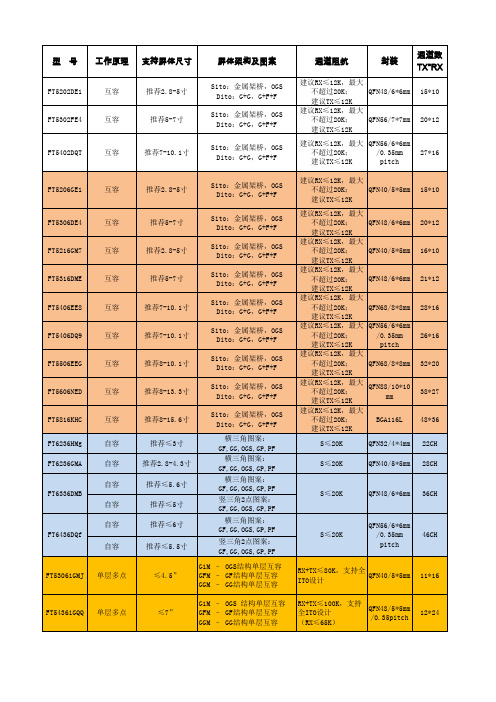
20*12
FT5402DQT
互容
推荐7-10.1寸
27*16
FT5206GE1
互容
推荐2.8-5寸
Sito:金属架桥,OGS Dito:G+G,G+F+F Sito:金属架桥,OGS Dito:G+G,G+F+F Sito:金属架桥,OGS Dito:G+G,G+F+F Sito:金属架桥,OGS Dito:G+G,G+F+F Sito:金属架桥,OGS Dito:G+G,G+F+F Sito:金属架桥,OGS Dito:G+G,G+F+F Sito:金属架桥,OGS Dito:G+G,G+F+F Sito:金属架桥,OGS Dito:G+G,G+F+F Sito:金属架桥,OGS Dito:G+G,G+F+F 横三角图案: GF,GG,OGS,GP,PF 横三角图案: GF,GG,OGS,GP,PF 横三角图案: GF,GG,OGS,GP,PF 竖三角2点图案: GF,GG,OGS,GP,PF 横三角图案: GF,GG,OGS,GP,PF 竖三角2点图案: GF,GG,OGS,GP,PF G1M – OGS结构单层互容 GFM – GF结构单层互容 GGM – GG结构单层互容 G1M – OGS 结构单层互容 GFM – GF结构单层互容 GGM – GG结构单层互容
工作电流:6mA 待机电流:4mA 睡眠电流:30uA
工作温度: -20~+85 储存温度: -55~+150 工作温度: -20~+85 储存温度: -55~+150
低温甲醇洗设备一览表

T设计=-75/+50℃
F=89M2
1
壳侧:低温碳
钢
管侧:低温碳 钢
20
E-1020
含硫甲醇厚氨冷器
壳程:P设计=FV 1.6 MPa(G)
T设计=-45/+50℃
管程:P设计=6.1MPa(G)
T设计=-45/+60℃
F=57M2
1
壳侧:低温碳
P设计=1.5MPa(G)
T设计=-60/+50℃
Q=240M3/h
2
外壳:不锈钢
序号
设备位号
设备名称和详细规格
数量
材料
备注
31
T-1001A/B
CO2吸收塔
P设计=5.8MPa(G)
T设计=-70,-45/+50℃
浮阀塔盘,(1800/2200)IDX66000Hmm
2
外壳:低温碳
钢
塔盘:不锈钢 浮阀:不锈钢
34
T-1004
甲醇再生塔
P设计=0.4MPa(G)
T设计=120℃
浮阀塔盘,(3400/2400)IDX21550Hmm
外壳:碳钢
塔盘:不锈钢
浮阀:不锈钢
35
T-1005
甲醇/水分离塔
P设计=0.4MPa(G)
T设计=170℃
复合塔板,(1000)IDX22475Hmm
外壳:碳钢
塔盘:不锈钢
浮阀:不锈钢
T设计=-45/+50℃
卧式,2600IDX8000Lmm
1
低温碳钢
39
V-1004
甲醇中间贮罐
维克托利克公司产品说明书
ALWAYS REFER TO ANY NOTIFICATIONS AT THE END OF THIS DOCUMENT REGARDING PRODUCT INSTALLATION, MAINTENANCE OR SUPPORT.(By Others)Series 78USeries 786Series 78TSUPPLY1.0 PRODUCT DESCRIPTIONAvailable Sizes• ½ – 2”/DN15 – DN50Maximum Working Pressure • 400 psi/2758 kPa/27.6 bar Operating Temperature Range• –4°F to +230°F/–20°C to +110°CFunction• Provides simplified coil circuit installation that meets optimal hydronic system design requirements Application• Hot and cold water, including treated and untreated water systems • This KOIL-KIT ™ Coil Pack includes:• (1) Series 78T Ball Valve Union Combination – Sweat x Sweat • (1) Series 78U Union Port Fitting – Sweat x Male Union • (1) TA Series 786H Balancing Valve – Sweat x SweatNOTE• The Series 78T includes a PT port and a blow-down valve. The Series 78U includes a PT port and a manual air vent.2.0 CERTIFICATI N/LISTINGSProduct designed and manufactured under the Victaulic Quality Management System, as certified by LPCB in accordance with ISO-9001:2008.Series 78T/78U Manual Koil-Kit ™ Coil Pack with TA Series 786H Sweat Globe Style Valve08.63System No.Location Submitted ByDateSpec Section Paragraph ApprovedDateSeries 78T Ball Valve Union Combination Body: Dezincification resistant (DZR) brass alloy Union: DZR brass with EPDM O-ring Tailpiece: DZR brassStem: BrassStem O-Ring Seals: EPDMHandle: Steel with vinyl gripSeries 78U Union Port FittingBody: DZR brass alloyUnion: DZR brass with EPDM O-ringSeals: EPDM O-ringTailpiece: DZR brass alloyTA Series 786H Balancing ValveValve Body and Bonnet: AMETAL® DZR brass alloy Sealing (Body/Bonnet): EPDM O-ringValve Plug: AMETAL®Seat Seal: EPDM O-ringSpindle: AMETAL®Slip Washer: Polytetrafluoroethylene (PTFE) Spindle Seal: EPDM O-ringSpring: Stainless steelHand Wheel: Polyamide and TPEMeasuring Points: AMETAL®Measuring Point Seals: EPDMMeasuring Point Caps: Polyamide and TPENOTE• AMETAL® is the dezincification-resistant brass alloy of IMI TA.Series 78T Ball Valve Union CombinationNOTE• Optional tailpieces may be ordered for reductions and for changing end configurations from sweat to threaded or threaded to sweat. If needed, specify optional tailpiece when ordering.Series 78U Union Port FittingNOTE• Optional tailpieces may be ordered for reductions and for changing end configurations from sweat to threaded or threaded to sweat. If needed, specify optional tailpiece when ordering.4.3 OPTIONAL PARTSSeries 78T/78U Union Tailpieces (Optional)Female Tailpiece Sweat Tailpiece Male TailpieceHose End Drain Valve (Optional)A hose end drain valve is factory-installed on the Series 78T.4.5 OPTIONAL PARTSProbe Port (Optional)For Series 78T and Series 78UHandle Extension (Optional)For Series 78T4.7 OPTIONAL PARTSAir VentA manual air vent is factory-installed on the Series 78U. This product can also be mounted on the Series 78T or provided loose for other piping needs.C V /K V values for flow of water at +60°F/+16°C are shown in the table.Formulas for C V and K V valuesΔP = Q 2/C V 2 ΔP = Q 2/K V 2Q = C V × √ΔPQ = K V × √ΔPSeries 78T Ball Valve Union CombinationSeries 78U Union Port FittingFlow CoefficientC v K v Q (Flow)GPM m3/hr ΔP (Pressure Drop)psibarWhere:TA Series 786H Balancing Valve Valve Selection GuideNOTES• Balancing valves should be sized in accordance with the GPM/LPM flows (and not in relation to pipeline size). Sizing balancing valves based on the minimumor maximum flow rates is not recommended. Valves should be sized using the nominal flow rate only. The Minimum Flow is calculated from the minimum open setting of the valve and a minimum pressure drop 1 Ft. WG (= 3 kPa). The Nominal Flow is calculated from the maximum open setting of the valve and the minimum recommended pressure drop, 2 Ft. WG (= 6 kPa). The Maximum Flow is calculated from the maximum open setting of the valve and the maximum pressure drop, 20 Ft. WG (= 60 kPa). A computer program, TA-Select, is available for calculation of valve handwheel pre-set position and other applications.• For information regarding Allen Wrench sizes see the Material Specifications section on page 3.• Measuring Accuracy: The hand wheel zero position is calibrated and must not be changed. Valves have an accuracy of flow measurement of 2% to 3% whenused within their recommended flow range and installed in accordance with the figure below.• For the most accurate results, a Series 734 TA SCOPE or Series 73M CMI should be used. However, any differential pressure meter may be used.The illustration relates to the accuracy of differential pressure measurement and is not an installation requirement.2 D 10 D2 D 5 D 5.2 PERF RMANCETA Series 786H Balancing Valve Cv Values for Various Handle SettingsThe values below may be used when calculating and sizing a piping system.1C V = GPM at a ΔP of 1 psi/7 kPa) through the valve at any given setting.1 psi = 2.31 ft. of H 2O 2Full open valve.For liquids other than water, the flow values from the balancing wheel can be adjusted as follows:Divide the flow rate by the square root of the specific gravity.This applies to liquids having, on the whole, the same viscosity as water, i.e. most water/glycol mixtures and water/brine solutions at room temperature. At low temperatures, the viscosity increases and laminar flow may occur in certain valves. The risk increases with small valves, low settings and low differential pressures.A computer program (Hy-Select) is available for calculation of pre-setting values and other applications. When the flow setting is verified or changed to the final setting, the memory stop should be set. Contact Victaulic for further information. When Δp and the design flow rate are known, use the formula shown to calculate the C V value.A computer program, Hy-Select, is available from Victaulic for calculation of pre-setting values and other applications.5.4 PART CODES08.63 11841 Rev B Updated 04/2020 © 2020 Victaulic Company. All rights reserved.User Responsibility for Product Selection and SuitabilityEach user bears final responsibility for making a determination as to the suitability of Victaulic products for a particular end-use application, in accordance with industry standards and project specifications, and the applicable building codes and related regulations as well as Victaulic performance, maintenance, safety, and warninginstructions. Nothing in this or any other document, nor any verbal recommendation,advice, or opinion from any Victaulic employee, shall be deemed to alter, vary, supersede, or waive any provision of Victaulic Company's standard conditions of sale, installation guide, or this disclaimer.Intellectual Property RightsNo statement contained herein concerning a possible or suggested use of any material, product, service, or design is intended, or should be constructed, to grant any license under any patent or other intellectual property right of Victaulic or any of its subsidiaries or affiliates covering such use or design, or as a recommendation for the use of suchmaterial, product, service, or design in the infringement of any patent or other intellectual property right. The terms “Patented” or “Patent Pending” refer to design or utility patents or patent applications for articles and/or methods of use in the United States and/or other countries.NoteThis product shall be manufactured by Victaulic or to Victaulic specifications. Victaulic recommends all products to be installed in accordance with current IMI TA installation/assembly instructions. Victaulic and IMI TA reserve the right to change productspecifications, designs and standard equipment without notice and without incurring obligations.InstallationReference should always be made to the current IMI TA installation/assembly instructions for the product you are installing. For coupling and strainer installation, reference should always be made to the I-100 Victaulic Field Installation Handbook for the product you are installing. Handbooks are included with each shipment of Victaulic products for complete installation and assembly data, and are available in PDF format on our website at WarrantyRefer to the Warranty section of the current Price List or contact Victaulic for details.TrademarksVictaulic and all other Victaulic marks are the trademarks or registered trademarks of Victaulic Company, and/or its affiliated entities, in the U.S. and/or other countries.7.0 REFERENCE MATERIALS08.16: Victaulic Balancing Valves - TA Series 786H/787H/788/789 and Series 78KH I-KOIL-KIT: Victaulic KOIL-KIT™ Coil Pack Installation and Maintenance Instructions11。
混凝土强度标准值
附表22注:1.计算现浇钢筋混凝土轴心受压及偏心受压构件时,如截面的长边或直径小于 300mm ,则表中混凝土 的强度设计值应乘以系数 0.8;当构件质量(如混凝土成型、截面和轴线尺寸等)确定保证时,可不受此限制;2.离心混凝土的强度设计值应按有关专门标准取用。
2) E 2.20 2.55 2.80 3.00 3.15 3.25 3.35 3.45 3.55 3.60 3.65 3.70 3.75 3.80c γ ρ γ ρ0.740.800.860.931.0注:如采用蒸汽养护时,养护温度不宜超过 600C ,如超过时,应按计算需要的混凝土强度设计值提高 20%。
2)E c f1.1 1.2 1.3 1.4 1.5 1.55 1.6 1.65 1.7 1.75 1.8 1.851.92)2)注:1.钢绞线直径 d系指钢绞线外接圆直径,即钢绞线标准 GB/T5224中的公称直径 Dg;2.各种直径钢绞线、钢丝、钢筋的公称截面面积如附录 B所示。
3.消除应力光面钢丝直径 d为 4~9mm,消除应力螺旋肋钢丝直径 d为 4~8mm。
2)注:1.在钢筋混凝土结构中,轴心受拉和小偏心受拉的钢筋抗拉强度设计值大于300N/mm2时,仍应按300N/mm2取用;2.构件中配有不同种类的钢筋时,每种钢筋应采用各自的强度设计值。
2)注:当预应力钢绞线、钢丝的强度标准值不符合表 4.2.2—2的规定时,其强度设计值应进行换算。
2)钢绞线10注:必要时钢绞线可采用实测的弹性模量。
2)注:1.当纵向受拉钢筋采用闪光接触对焊接头时,其接头处钢筋疲劳应力幅限值应按表中数值乘以系数0.8;2.RRB400级钢筋须经试验严正吼,方可用于需做疲劳验算的构件。
注:当f 2)ρ p 不小于 0.9 时,不必作钢筋疲劳验算。
附表 13混凝土构件中纵向受力钢筋的最小配筋百分率 min (%)注:1.轴心受压构件、偏心受压构件全部纵向钢筋的配筋率以及各类构件一侧受压钢筋的配筋率应按构件的全截面面积计算;轴心受拉构件及小偏心受拉构件一侧受拉钢筋的配筋率应按构件的全截面面积计算;受弯梁类构件、大偏心受拉构件一侧受拉钢筋的配筋率应按全截面面积扣除受压边缘面积//( b f − b) h f 后的截面面积计算。
赛米控丹佛斯 分立晶闸管 SKT 883 数据表
Capsule Thyristor ThyristorsSKT 883Features∙Hermetic metal case with epoxy insulator∙Capsule package for double sided cooling∙Off-state and reverse voltages up to 1800 V∙Amplifying gateTypical Applications *∙DC motor control(e.g. for machine tools)∙Controlled and half-controlled rectifiers(e.g. for battery charging)∙AC controllers(e.g. for temperature control)∙Recommended snubbernetworke.g. for V RMS≤ 400 V:R = 33 Ω/32 W, C = 1 µFSKTV RSMVV RRM, V DRMVI TRMS = 1800 A (maximum value for continuous operation)I TAV = 880 A (sin. 180 DSC; T c = 85 ºC)500 400 SKT 883/04D900 800 SKT 883/08D1300 1200 SKT 883/12E1700 1600 SKT 883/16E1900 1800 SKT 883/18ESymbol Condition Values Units I TAVI DI RMSsin. 180 ; T C = 100 (85) ºC2 x P8/180; T a = 45 ºC; B2/B62 x P8/180F; T a = 35 ºC; B2/B62 x P8/180; T a = 45 ºC; W1C624 (880)470 / 6851345 / 1870525AAAAI TSM T vj = 25º C ; 10 ms 19000 AT vj = 125º C ; 10 ms 15500 Ai2t T vj = 25º C ; 8,3...10 ms 1805000 A2s T vj = 125º C ; 8,3...10 ms 1200000 A2s V T T vj = 25º C, I T = 2400 A max. 1,51 VV T(TO)T vj = 125º C max. 0,85 Vr T T vj = 125º C max. 0,26 mΩI DD; I RD T vj = 125º C; V DD = V DRM; V RD = V RRM max. 90 mA t gdt grT vj = 25º C; i G = 1A; di G/d t = 1 A/µsV D = 0,67 * V DRM12µsµs (d i/d t)cr(d V/d t)crt qI HI LT vj = 125°CT vj = 125°C; D (E)T vj = 125°CT vj = 25°C; typ. / maxT vj = 25°C; R G = 33 Ω; typ. / maxmax. 125500 (1000)100 (200)150 / 500300 / 2000A/µsV/µsµsmAmA V GTI GTV GDI GDT vj = 25°C; d.c.T vj = 25°C; d.c.T vj = 125°C; d.c.T vj = 125°C; d.c.min. 3min. 200max. 0,25max. 10VmAVmA R th(j-c)R th(j-c)R th(j-c)R th(c-s)T vjT stgcont.; DSCsin. 180; DSC / SSCrec. 120; DSC / SSCDSC / SSC3032 / 6637 / 775 / 10-40...+125-40...+125mK/WmK/WmK/WmK/W°C°C F Mounting force ( SI units ) 13 … 17 kN m approx. 280 g Case B23Fig. 1L Power dissipation vs. forward current Fig. 4 Forward characteristicsFig. 6 Forward current vs. case temperature Fig. 1R Power dissipation vs. ambient temperature Fig. 5 Surge overload current vs. timeFig. 7 Transient thermal impedance vs. timeFig. 9 Gate trigger characteristicsDimensions in mmOrdering code: 38588600 (1 pair) G / HK Leads – Separately availableDimensions in mmCase B23*IMPORTANT INFORMATION AND WARNINGSThe specifications of SEMIKRON products may not be considered as guarantee or assurance of product characteristics ("Beschaffenheitsgarantie"). The specifications of SEMIKRON products describe only the usual characteristics of products to be expected in typical applications, which may still vary depending on the specific application. Therefore, products must be tested for the respective application in advance. Application adjustments may be necessary. The user of SEMIKRON products is responsible for the safety of their applications embedding SEMIKRON products and must take adequate safety measures to prevent the applications from causing a physical injury, fire or other problem if any of SEMIKRON products become faulty. The user is responsible to make sure that the application design is compliant with all applicable laws, regulations, norms and standards. Except as otherwise explicitly approved by SEMIKRON in a written document signed by authorized representatives of SEMIKRON, SEMIKRON products may not be used in any applications where a failure of the product or any consequences of the use thereof can reasonably be expected to result in personal injury. No representation or warranty is given and no liability is assumed with respect to the accuracy, completeness and/or use of an y information herein, including without limitation, warranties of non-infringement of intellectual property rights of any third party. SEMIKRON does not assume any liability arising out of the applications or use of any product; neither does it convey any license under its patent rights, copyrights, trade secrets or other intellectual property rights, nor the rights of others. SEMIKRON makes no representation or warranty of non-infringement or alleged noninfringement of intellectual property rights of any third party which may arise from applications. Due to technical requirements our products may contain dangerous substances. For information on the types in question please contact the nearest SEMIKRON sales office. This document supersedes and replaces all information previously supplied and may be superseded by updates. SEMIKRON reserves the right to make changes.。
TH2817C+系列仪器使用说明书 Ver1.1
使用说明书OPERATION MANUALTH2817C+紧凑型LCR数字电桥TH2817C+ Compact LCR Meter版本历史:*******————————————————————2019/2/19*******————————————————————2020/1/17本说明书所描述的可能并非仪器所有内容,同惠公司有权对本产品的性能、功能、内部结构、外观、附件、包装物等进行改进和提高而不作另行说明!由此引起的说明书与仪器不一致的困惑,可通过封面的地址与我公司进行联系。
第1章开箱安装13 1.1开箱检查13 1.2电源连接13 1.3保险丝13 1.4环境13 1.5使用测试夹具14 1.6预热14 1.7仪器的其它特性14第2章概述15 2.1前面板说明15 2.2面板说明17 2.3显示区域定义18 2.4主菜单按键和相应显示的页面192.4.1显示主菜单按键[DISP] 192.4.2参数设置主菜单按键[SETUP] 202.4.3系统设置主菜单按键[SETUP] 20 2.5基本操作21 2.6开机21第3章[DISP]菜单键说明223.1<平衡测量显示>页面223.2<元件测量显示>页面22 3.2.1测试功能24 3.2.2测试量程28 3.2.3测试频率29 3.2.4测试电平30 3.2.5测试速度30 3.2.6其它工具30 3.2.7标称值31 3.2.8触发方式31 3.2.9 R下限和R上限32 3.2.10 X下限和X上限34 3.3<档号显示>页面34 3.3.1比较器功能35 3.4<档计数显示>页面36 3.4.1参数36 3.4.2标称36 3.4.3档37 3.4.4上下限37 3.4.5计数373.4.6附属(AUX) 37 3.4.7超差(OUT) 37 3.5<列表扫描>页面37 3.5.1扫描模式39 3.5.2扫描显示(显示) 39 3.5.3频率[Hz] 电平[V] 39 3.5.4 Ls[H] Q[ ] 39 3.5.5多功能扫描40 3.5.6 CMP(比较)40 3.6<平衡极限设置>页面41 3.6.1比较功能42 3.6.2偏差扣除42 3.6.3直流电阻A 42 3.6.4各功能的上下限值42 3.6.5标称值42 3.6.6偏差值42 3.7<测量设置>页面43 3.7.1平均次数44 3.7.2电平电流监视功能443.7.3触发延时45 3.7.4步进延时45 3.7.5输出电阻45 3.7.6偏差测试功能46 3.8<用户校正>页面47 3.8.1开路校正48 3.8.2短路校正49 3.8.3负载校正51 3.8.4负载校正测试功能52 3.8.5点频校正52 3.8.6电缆长度选择52 3.9<极限列表设置>页面53 3.9.1对调参数53 3.9.2比较功能极限模式54 3.9.3容差方式标称值设置55 3.9.4比较器功能ON/OFF 55 3.9.5附属档ON/OFF 56 3.9.6上下极限56 3.10<列表扫描设置>页面573.10.1模式583.10.2扫描显示583.10.3测试参数583.10.4扫描参数设置593.10.5多功能设置59 3.11<工具>页面603.11.1校正数据603.11.2空夹具判别603.11.3锁定标称量程613.11.4自动返回数据613.11.5 HDL 有效时间613.11.6自动LCR功能61第4章[SYSTEM]菜单键说明和文件管理624.1<系统设置>页面624.1.1仪器功能624.1.2合格讯响624.1.3不良讯响634.1.4显示语言634.1.5口令644.1.6总线方式644.1.7 GPIB地址(预留功能)644.1.8只讲(Talk Only)654.1.9波特率654.1.10菜单保持654.1.11通讯协议664.1.12时间664.1.13默认设置664.1.14系统复位66 4.2<HANDLER>页面66 4.3<文件管理>页面674.3.1单组元件设定文件(*.STA)684.3.2 TH2817C+系列仪器的优盘管理性能694.3.3文件管理操作步骤:69第5章执行LCR测量操作及一些示例725.1“清零”校正操作725.1.1全频清零:725.1.2点频清零(对于使用单个频率测试的情况比较好):72 5.2被测元件的正确连接735.3消除杂散阻抗的影响74 5.4用TH2817C+测试电感快速操作实例75 5.5用TH2817C+作多频列表扫描测试电容快速操作实例76 5.6比较器设置实例775.6.1电容器分选785.6.2负载校准操作实例79第6章性能与测试81 6.1测量功能816.1.1测量参数及符号816.1.2等效方式816.1.3量程816.1.4触发816.1.5触发延时816.1.6测试端连接方式826.1.7测量速度(频率>=10kHz时)826.1.8平均826.1.9显示位数826.1.10测试信号频率826.1.11信号模式826.1.12测试信号电平82 6.1.13输出阻抗82 6.1.14测试信号电平监视器83 6.1.15测量显示最大范围83 6.1.16│Z│、│Y│、L、C、R、X、G、B的准确度83 6.1.17 D 准确度84 6.1.18 Q 准确度84 6.1.19θ 准确度84 6.1.20 G 准确度84 6.1.21 Rp 准确度85 6.1.22 Rs 准确度85 6.1.23准确度因子86 6.1.24漏电感Lk 准确度88 6.2安全要求89 6.2.1绝缘电阻89 6.2.2绝缘强度89 6.2.3泄漏电流89 6.3电磁兼容性要求89 6.4性能测试896.4.1工作条件896.4.2试验仪器和设备见下表。
- 1、下载文档前请自行甄别文档内容的完整性,平台不提供额外的编辑、内容补充、找答案等附加服务。
- 2、"仅部分预览"的文档,不可在线预览部分如存在完整性等问题,可反馈申请退款(可完整预览的文档不适用该条件!)。
- 3、如文档侵犯您的权益,请联系客服反馈,我们会尽快为您处理(人工客服工作时间:9:00-18:30)。
概述 ............................................................................................... 2 系统体系 ...................................................................................... 3 操作特性 ...................................................................................... 5 模式组合 ...................................................................................... 6 维修拆卸 .................................................................................... 16 电路说明 .................................................................................... 22 半导体数据 ................................................................................ 30 元件说明 .................................................................................... 32 端子功能 .................................................................................... 33 零件表 ........................................................................................ 34 部件分解图 ................................................................................ 40 包装 ............................................................................................. 41 调整 ............................................................................................. 42 PC 板
TX-RX UNIT (X57-7130-21) .......................... 52 SCHEMATIC DIAGRAM ..................................... 56 BLOCK DIAGRAM .............................................. 60 LEVEL DIAGRAM ............................................... 62 KSC-31 / KNB-29N / KBH-10 ............................ 63 SPECIFICATIONS ............................................... 64
PERSONAL SAFETY
The following precautions are recommended for personal safety: • DO NOT transmit until all RF connectors are verified secure
and any open connectors are properly terminated. • SHUT OFF and DO NOT operate this equipment near
TK-3217
CONTENTS / 目录
GENERAL ............................................................. 2 SYSTEM SET-UP ................................................. 3 OPERATING FEATURES ..................................... 4 REALIGNMENT .................................................... 6 DISASSEMBLY FOR REPAIR ............................ 16 CIRCUIT DESCRIPTION ..................................... 22 SEMICONDUCTOR DATA ................................. 30 COMPONENTS DESCRIPTION ......................... 32 TERMINAL FUNCTION ...................................... 33 PARTS LIST ........................................................ 34 EXPLODED VIEW ............................................... 40 PACKING ............................................................ 41 ADJUSTMENT ................................................... 42 PC BOARD
electrical blasting caps or in an explosive atmosphere. • This equipment should be serviced by a qualified technician only.
2
引言
本手册的范围 本手TX-RX 单元 (X57-7130-21) ............................................ 52 原理图 ........................................................................................ 56 方块图 ........................................................................................ 60 电平图 ........................................................................................ 62 KSC-31 / KNB-29N / KBH-10 ................................................... 63 规格 ............................................................................................. 65
GENERAL / 概述
INTRODUCTION
SCOPE OF THIS MANUAL This manual is intended for use by experienced technicians
familiar with similar types of commercial grade communications equipment. It contains all required service information for the equipment and is current as of the publication date. Changes which may occur after publication are covered by either Service Bulletins or Manual Revisions. These are issued as required.
Cabinet assy 机壳 (A02-3894-23)
Key top 顶端按键
(K29-9346-02)
Does not come with antenna. Antenna is available as an option. 不包括天线。天线为选件。
This product uses Lead Free solder
ORDERING REPLACEMENT PARTS
When ordering replacement parts or equipment information, the full part identification number should be included. This applies to all parts : components, kits, or chassis. If the part number is not known, include the chassis or kit number of which it is a part, and a sufficient description of the required component for proper identification.