(整理)MDK90-16整流管模块.
freescale MC9S12P128中文手册
Chapter1 Device Overview MC9S12P-Family 介绍The MC9S12P 系列单片机是经过优化后有着低成本、高性能、低引脚数的汽车专业级单片机产品,该产品倾向于弥补高端16位单片及产品如MC9S12XS和低端8位单片机产品之间的空缺。
MC9S12P 主要针对于要求使用CAN 或者 LIN/J2602通讯接口的汽车应用产品,典型的应用案例包括车身控制器、乘坐人员检测、车门控制、座椅控制、遥控车门开关信号接收器、智能执行器、车灯模块、智能接线器。
The MC9S12P 系列单片机使用了很多MC9S12XS系列单片机相同的功能,包括片内闪存错误纠正代码(ECC)、一个专为数据诊断或者数据存储的单独的数据闪存模块、高速AD转换器和高频调制锁相环(IPLL)有效改善电磁兼容性能。
MC9S12P系列单片机提供的所有16为单片机优点和微处理器效率,同时保持飞思卡尔用户熟悉的8位及16位单片机,低成本,功耗,EMC和高效的代码80针QFP、64针LQFP、40针QFN封装产品,最大限度的与MC9S12尺寸的优点,如同MC9S12XS一样可以无需等待外围设备和内存的状态既可以运行16为带款的寻址,MC9S12P系列单片机主要有XS引脚兼容. I/O口在各种模式下都可以使用,同时具有中断功能的I/O口还可以在停止或等待模式下唤醒。
芯片特性表一:提供了MC9S12P家庭成员特征摘要,或D寄存器擦除或者编程需要最低总线频率为1MHZ芯片功能• S12 CPU 内核• 高达128 KB具有ECC功能的片上闪存• 4 Kbyte带ECC功能的数据闪存• 高达6 Kb片上静态存储器(SRAM)• 具有内部滤波器的锁相环倍频器 (IPLL)• 4–16 MHz 皮尔斯振荡器• 1 MHz内部RC振荡器• 定时器 (TIM) 具有16位输入捕捉、输出比较、计数器脉冲累加器功能• 具有8位6通道的脉冲调制模块(PWM)• 10通道12位分辨率的逐次逼近AD转换器• 1个串行通信外部接口(SPI)• 1个支持局域网通讯串行通信(SCI) 模块•一个多可扩展控制器区域网络(MSCAN) 模块 (支持CAN 协议B)•片上电压调节器 (VREG) 可对内部供电及内部电压整流• 自主周期中断 (API)模块特征CPUS12 CPU 是一个高速的16位处理单元:•全16-bit数据通道提供有效的数学运算和高速的数学执行• 包含很多单字节指令,可以有效的利用ROM空间• 宽域变址寻址功能:—采用堆栈指针作为所有变址操作的变址寄存器—除了在自增或自减模式下都可以利用程序计数器作为变址寄存器—使用A\B\D累加器做累加器偏移—自动变址,前递增(++a)、前递减(--a)、后递减(a--)、后递增(a++)(by –8 to +8)带ECC功能的片内闪存• 高达 128 Kb程序闪存空间— 32 位数据加7 位ECC (纠错码) 允许单字节纠错和双字节纠错— 512字节擦出扇区空间—自动编程和擦除算法—用户设置读写页面边界—具有可以防止偶然编程或者擦除的保护结构• 4 Kb 数据闪存空间— 16 位数据加6位纠错码允许单字节和双字节纠错功能— 256 字节的擦出扇区空间—自动编程和擦除算法—用户设置读写页面边界片内静态存储器高达6kb通用RAM外部晶振 (XOSC)• 闭环控制皮尔斯晶振频率为4MHZ---16MHZ—振幅增益控制输出电流—低谐波失真信号Signal with low harmonic distortion—低功耗—良好的噪声免疫—无需外部限流电阻—跨导尺寸优化提供良好的振荡器启动保证内部RC晶振 (IRC)• 可调的内部参考时钟—频率: 1 MHz—在–40°C to +125°C环境温度范围内调节精度达: %内部锁相环倍频器(IPLL)—无需外部元件—参考分频器和倍频器提供大变化量的时钟频率—自动带宽控制低频率抖动操作—自动锁定频率—可配置的选项,扩频减少电磁干扰EMC (频率调制frequency modulation)—参考时钟源:–外部 4–16 MHz 共振器/晶振 (XOSC)–内部RC晶振 1 MHz (IRC)系统支撑• 上电复位(POR)• 系统复位发生器• 非法寻址复位•低电压检测中断或复位• 实时中断 (RTI)• 计算机正常工作复位(COP) 开门狗—可通过相应窗口设置COP用以采用错误侦测复位通过位操作对闪存进行初始化复位•时钟监控器监控晶振功能正常工作定时器(TIM)• 8通道16位定时器可进行输入捕捉和输出比较• 16-bit带有7位精度预分频器的自由运行计数器•一通道16-bit 脉冲累加器脉冲带宽调制器 (PWM)• 6通道8位or 3 通道16-bit脉宽调制器—每个通道都可以对周期和占空比进行编程—中心对齐或者左对齐输出—宽频率范围内可编程逻辑时钟局域网控制器 (MSCAN)•速率达1Mbit/s, 满足CAN A, B 协议—标准和扩展数据帧— 0–8 字节长度—可编程比特率达1 Mbps•5个 FIFO(先进先出)的接收缓冲器•三个内部优先发送缓冲器• 灵活的标识符可编程选通滤波器s:— 2 x 32-bit— 4 x 16-bit— 8 x 8-bit•集成了低通滤波器的唤醒操作• 闭环反馈自检测• CAN 总线监听•总线关闭可通过软件干预或者自动恢复• 16-bit 接收发送信息时钟戳串行通信接口 (SCI)•可选择全双工或单工模式•标准的不归零格式•通过可编程脉宽调制选用 IrDA 反转归零格式• 13位波特率可选•可编程字符长度•可编程改变其接收和发送极性for transmitter and receiver •边沿触发接收唤醒•支持LIN总线的间隔检测和传输冲突检测Serial Peripheral Interface Module (SPI)•可配置 8- or 16-bit 数据大小•全双工或单线双向•全双工接收和发送• Master or slave 模式•最高位优先 or 最低位优先可换• 并口时钟频率相位和极性选择AD转换 (ATD)• 10通道12位AD转换器— 3微妙转换时间— 8-/10-/12-位解决方案—数据结果左对齐或右对齐—停止模式下使用内部晶振作为转换器晶振—低功耗模式下模拟信号比较唤醒—连续转换模式e—多通道扫描•引脚可作为IO口片内电压调节器(VREG)•具有带隙标准的线性电压稳压器• 具有低电压中断功能的低压检测器•上电复位 (POR) 电路•低电压复位功能 (LVR)•高温传感器背景调试 (BDM)• 非插入内存访问指令• 支持在线对片内非易始性存储单元编程调试器 (DBG)•64个入口跟踪缓冲器• 三个比较器 (A, B and C)—比较器A比较全16位地址总线额16位数据总线—精确寻址和寻址范围比较•两种匹配比较类型—标记位—程序强行置位该类型是在一数学公式出现后一个指令边界可用•四个跟踪模式•四个阶段状态序列发生器 stage state sequencer内部结构框图引脚图存储器映像表Table 1-2. Device Register Memory Map注意在表1-2中保留的寄存器空间不分配给任何模块,该寄存器的保留空间是留给以后使用的,对这些保留空间写操作没有任何效果,读该空间返回值都为零。
Kinetix 运动控制选型指南

基于 SERCOS 接口实现集成运动控制的多轴驱动器系列,包括 IAM ( 整流单元 ) 模块和 AM ( 逆变单 元 ) 模块,并且采用安全关断控制机制。
旋转运动 直线运动
使用 Motion Analyzer 软件
Motion Analyzer 软件是一款全面的测量工具,用于 Kinetix 运动控制系统的分析、优化、选型及验证。给定任何驱动 器和兼容的电机 / 执行器后, Motion Analyzer 软件将提供相关数据以确定适合应用项目的最佳驱动器和电机 / 执行 器组合。
合并为一个系统后,即可提供经济实用的运动控制解决方案,并为您带来在当今行 业竞争中致胜所需的高性能和可扩展性。 Kinetix 350 结构紧凑,所需的面板空间更 少,连接非常简单。此外,在整个机器产品系列中,各集成产品之间代码可重复使 用,降低了您的安装和调试时间。
本出版物的第 10 页 和第 71 页以及 Kinetix Servo Drives Specifications
• 后 U 形夹安装:所有表面都涂有环氧涂层,包括 U 形夹安装件,它在支 轴点和磨损点装有不锈钢垫片。
新品的框架尺寸为 83 mm,行程长度更短,仅为 76.2 mm (3.0 in.)。
Data (Kinetix 直线运动产 品技术参数数据,出版 号:GMC-TD002)。
此次改进还新增了 Bulletin MPAI ( 框架 144) 电动缸。这些执行器可用于标准和食品级 涂层滚珠丝杠配置中,将最大进给力额定值和系统连续堵转力额定值分别增大到了 14,679 N (3300 lb) 和 13,122 N (2950 lb)。
freescale MC9S12P128中文手册

1Chapter1 Device Overview MC9S12P-Family 1.1介绍The MC9S12P 系列单片机是经过优化后有着低成本、高性能、低引脚数的汽车专业级单片机产品,该产品倾向于弥补高端16位单片及产品如MC9S12XS和低端8位单片机产品之间的空缺。
MC9S12P 主要针对于要求使用CAN 或者LIN/J2602通讯接口的汽车应用产品,典型的应用案例包括车身控制器、乘坐人员检测、车门控制、座椅控制、遥控车门开关信号接收器、智能执行器、车灯模块、智能接线器。
The MC9S12P 系列单片机使用了很多MC9S12XS系列单片机相同的功能,包括片内闪存错误纠正代码(ECC)、一个专为数据诊断或者数据存储的单独的数据闪存模块、高速AD转换器和高频调制锁相环(IPLL)有效改善电磁兼容性能。
MC9S12P系列单片机提供的所有16为单片机优点和微处理器效率,同时保持飞思卡尔用户熟悉的8位及16位单片机,低成本,功耗,EMC和高效的代码80针QFP、64针LQFP、40针QFN封装产品,最大限度的与MC9S12尺寸的优点,如同MC9S12XS一样可以无需等待外围设备和内存的状态既可以运行16为带款的寻址,MC9S12P系列单片机主要有XS引脚兼容. I/O口在各种模式下都可以使用,同时具有中断功能的I/O口还可以在停止或等待模式下唤醒。
1.2 芯片特性表一:提供了MC9S12P家庭成员特征摘要,1.P或D寄存器擦除或者编程需要最低总线频率为1MHZ1.2.2 芯片功能• S12 CPU 内核• 高达128 KB具有ECC功能的片上闪存• 4 Kbyte带ECC功能的数据闪存• 高达6 Kb片上静态存储器(SRAM)• 具有内部滤波器的锁相环倍频器(IPLL)• 4–16 MHz 皮尔斯振荡器• 1 MHz内部RC振荡器• 定时器(TIM) 具有16位输入捕捉、输出比较、计数器脉冲累加器功能• 具有8位6通道的脉冲调制模块(PWM)• 10通道12位分辨率的逐次逼近AD转换器• 1个串行通信外部接口(SPI)• 1个支持局域网通讯串行通信(SCI) 模块•一个多可扩展控制器区域网络(MSCAN) 模块(支持CAN 协议2.0A/B)•片上电压调节器(VREG) 可对内部供电及内部电压整流• 自主周期中断(API)1.3 模块特征1.3.1 CPUS12 CPU 是一个高速的16位处理单元:•全16-bit数据通道提供有效的数学运算和高速的数学执行• 包含很多单字节指令,可以有效的利用ROM空间• 宽域变址寻址功能:—采用堆栈指针作为所有变址操作的变址寄存器—除了在自增或自减模式下都可以利用程序计数器作为变址寄存器—使用A\B\D累加器做累加器偏移—自动变址,前递增(++a)、前递减(--a)、后递减(a--)、后递增(a++)(by –8 to +8)1.3.2 带ECC功能的片内闪存• 高达128 Kb程序闪存空间— 32 位数据加7 位ECC (纠错码) 允许单字节纠错和双字节纠错— 512字节擦出扇区空间—自动编程和擦除算法—用户设置读写页面边界—具有可以防止偶然编程或者擦除的保护结构• 4 Kb 数据闪存空间— 16 位数据加6位纠错码允许单字节和双字节纠错功能— 256 字节的擦出扇区空间—自动编程和擦除算法—用户设置读写页面边界1.3.3 片内静态存储器3高达6kb通用RAM1.3.4 外部晶振(XOSC)• 闭环控制皮尔斯晶振频率为4MHZ---16MHZ—振幅增益控制输出电流—低谐波失真信号Signal with low harmonic distortion—低功耗—良好的噪声免疫—无需外部限流电阻—跨导尺寸优化提供良好的振荡器启动保证1.3.5 内部RC晶振(IRC)• 可调的内部参考时钟—频率: 1 MHz—在–40°C to +125°C环境温度范围内调节精度达: 1.5%1.3.6 内部锁相环倍频器(IPLL)—无需外部元件—参考分频器和倍频器提供大变化量的时钟频率—自动带宽控制低频率抖动操作—自动锁定频率—可配置的选项,扩频减少电磁干扰EMC (频率调制frequency modulation) —参考时钟源:–外部4–16 MHz 共振器/晶振(XOSC)–内部RC晶振1 MHz (IRC)1.3.7 系统支撑• 上电复位(POR)• 系统复位发生器• 非法寻址复位•低电压检测中断或复位• 实时中断(RTI)• 计算机正常工作复位(COP) 开门狗—可通过相应窗口设置COP用以采用错误侦测复位通过位操作对闪存进行初始化复位•时钟监控器监控晶振功能正常工作1.3.8 定时器(TIM)• 8通道16位定时器可进行输入捕捉和输出比较• 16-bit带有7位精度预分频器的自由运行计数器•一通道16-bit 脉冲累加器1.3.9 脉冲带宽调制器(PWM)• 6通道8位or 3 通道16-bit脉宽调制器—每个通道都可以对周期和占空比进行编程—中心对齐或者左对齐输出—宽频率范围内可编程逻辑时钟1.3.10 局域网控制器(MSCAN)•速率达1Mbit/s, 满足CAN 2.0 A, B 协议—标准和扩展数据帧— 0–8 字节长度—可编程比特率达1 Mbps•5个FIFO(先进先出)的接收缓冲器•三个内部优先发送缓冲器• 灵活的标识符可编程选通滤波器s:— 2 x 32-bit— 4 x 16-bit— 8 x 8-bit•集成了低通滤波器的唤醒操作• 闭环反馈自检测• CAN 总线监听•总线关闭可通过软件干预或者自动恢复• 16-bit 接收发送信息时钟戳1.3.11 串行通信接口(SCI)•可选择全双工或单工模式•标准的不归零格式•通过可编程脉宽调制选用IrDA 1.4 反转归零格式• 13位波特率可选•可编程字符长度•可编程改变其接收和发送极性for transmitter and receiver•边沿触发接收唤醒•支持LIN总线的间隔检测和传输冲突检测1.3.12 Serial Peripheral Interface Module (SPI) •可配置8- or 16-bit 数据大小•全双工或单线双向•全双工接收和发送• Master or slave 模式•最高位优先or 最低位优先可换• 并口时钟频率相位和极性选择1.3.13 AD转换(ATD)• 10通道12位AD转换器— 3微妙转换时间— 8-/10-/12-位解决方案5—数据结果左对齐或右对齐—停止模式下使用内部晶振作为转换器晶振—低功耗模式下模拟信号比较唤醒—连续转换模式e—多通道扫描•引脚可作为IO口1.3.14 片内电压调节器(VREG)•具有带隙标准的线性电压稳压器• 具有低电压中断功能的低压检测器•上电复位(POR) 电路•低电压复位功能(LVR)•高温传感器1.3.15 背景调试(BDM)• 非插入内存访问指令• 支持在线对片内非易始性存储单元编程1.3.16 调试器(DBG)•64个入口跟踪缓冲器• 三个比较器(A, B and C)—比较器A比较全16位地址总线额16位数据总线—精确寻址和寻址范围比较•两种匹配比较类型—标记位—程序强行置位该类型是在一数学公式出现后一个指令边界可用•四个跟踪模式•四个阶段状态序列发生器stage state sequencer1.4 内部结构框图71.5 引脚图1.6 存储器映像表Table 1-2. Device Register Memory Map注意在表1-2中保留的寄存器空间不分配给任何模块,该寄存器的保留空间是留给以后使用的,对这些保留空间写操作没有任何效果,读该空间返回值都为零。
RT9016-15GB中文资料
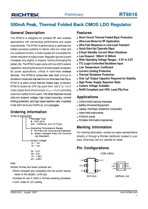
DS9016-03 August 2007500mA Peak, Thermal Folded Back CMOS LDO RegulatorMarking InformationFor marking information, contact our sales representative directly or through a Richtek distributor located in your area, otherwise visit our website for detail.Ordering InformationGeneral DescriptionThe RT9016 is designed for portable RF and wireless applications with demanding performance and space requirements. The RT9016 performance is optimized for battery-powered systems to deliver ultra low noise and low quiescent current. A noise bypass pin is available for further reduction of output noise. Regulator ground current increases only slightly in dropout, further prolonging the battery life. The RT9016 also works with low-ESR ceramic capacitors, reducing the amount of board space necessary for power applications, critical in hand-he ld wireless devices. The RT9016 consumes less than 0.01μA in shutdown mode and has fast turn-on time less than 50μs.RT9016 is short circuit thermal folded back protected.RT9016 lowers its OTP trip point from 165°C to 110°C when output short circuit occurs (V OUT < 0.4V) providing maximum safety to end users. The other features include ultra low dropout voltage, high output accuracy, current limiting protection, and high ripple rejection ratio. Available in the SOT-23-5 and WDFN-6L 2x2 p ackages.Featuresz Short Circuit Thermal Folded Back Protection z Ultra-Low-Noise for RF Applicationz Ultra-Fast Response in Line/Load Transient z Quick Start-Up (Typically 50μs)z 0.01μA Standby Current When Shutdown z Low Dropout : 380mV @ 500mAz Wide Operating Voltage Ranges : 2.5V to 5.5V z TTL-Logic-Controlled Shutdown Input z Low Temperature Coefficient z Current Limiting Protection z Thermal Shutdown Protectionz Only 1μF Output Capacitor Required for Stability z High Power Supply Rejection Ratio z Custom Voltage AvailablezRoHS Compliant and 100% Lead (Pb)-FreeApplicationsz CDMA/GSM Cellular Handsets z Battery-Powered Equipmentz Laptop, Palmtops, Notebook Computers z Hand-Held Instruments z PCMCIA CardszPortable Information AppliancesNote :Richtek Pb-free and Green products are :`RoHS compliant and compatible with the current require- ments of IPC/JEDEC J-STD-020.`Suitable for use in SnPb or Pb-free soldering processes.`100% matte tin (Sn) plating.Pin Configurations(TOP VIEW)SOT-23-5WDFN-6L 2x215 : 1.5V 16 : 1.6V :34 : 3.4V 35 : 3.5V 1H : 1.85V 2H : 2.85VEN GNDVINVIN GND BP VOUTENFunction Block DiagramFunctional Pin DescriptionTypical Application CircuitV V OUTBPENAbsolute Maximum Ratings (Note 1)z Supply Input Voltage------------------------------------------------------------------------------------------------------6Vz Power Dissipation, P D @ T A= 25°CSOT-23-5--------------------------------------------------------------------------------------------------------------------400mWWDFN-6L 2x2--------------------------------------------------------------------------------------------------------------606mWz Package Thermal Resistance (Note 4)SOT-23-5, θJA---------------------------------------------------------------------------------------------------------------250°C/W WDFN-6L 2x2, θJA---------------------------------------------------------------------------------------------------------165°C/Wz Lead Temperature (Soldering, 10 sec.)-------------------------------------------------------------------------------260°Cz Junction Temperature----------------------------------------------------------------------------------------------------150°Cz Storage T emperature Range--------------------------------------------------------------------------------------------−65°C to 150°C z ESD Susceptibility (Note 2)HBM (Human Body Mode)----------------------------------------------------------------------------------------------2kVMM (Machine Mode)------------------------------------------------------------------------------------------------------200V Recommended Operating Conditions (Note 3)z Supply Input Voltage------------------------------------------------------------------------------------------------------2.5V to 5.5Vz Junction T emperature Range--------------------------------------------------------------------------------------------−40°C to 125°C z Ambient T emperature Range--------------------------------------------------------------------------------------------−40°C to 85°C Electrical Characteristics(V IN = V OUT + 1V, C IN = C OUT = 1μF, C BP = 22nF, T A= 25°C, unless otherwise specified)To be continued DS9016-03 August Note 1. Stresses listed as the above "Absolute Maximum Ratings"may cause permanent damage to the device. These are for stress ratings. Functional operation of the device at these or any other conditions beyond those indicated in the operational sections of the specifications is not implied. Exposure to absolute maximum rating conditions for extended periods may remain possibility to affect device reliability.Note 2. Devices are ESD sensitive. Handling precaution recommended.Note 3. The device is not guaranteed to function outside its operating conditions.Note 4.θJA is measured in the natural convection at T A = 25°C on a low effective thermal conductivity test board (Single Layer, 1S) of JEDEC 51-3 thermal measurement standard.Note 5. The dropout voltage is defined as V IN -V OUT, which is measured when V OUT is V OUT(NORMAL)− 100mV.DS9016-03 August 2007Typical Operating CharacteristicsEN Pin Shoutdown Threshold vs. Temperature0.50.7511.251.51.75-50-25255075100125Temperature E N P i n S h o u t d o w n T h r e s h o l d (V )(°C)PSRR-80-60-40-20200.010.11101001000Frequency (kHz)P S R R (d B )10 100 1K 10K 100K 1M (Hz)Quiescent Current vs. Temperature6065707580859095-50-25255075100125Temperature Q u i e s c e n t C u r r e n t (u A )(°C)Output Voltage vs. Temperature1.21.31.41.51.61.71.8-50-25255075100125Temperature O u t p u t V o l t a g e (V )(°C)Dropout Voltage vs. Load Current01002003004005006000100200300400500Load Current (mA)D r o p o u t V o l t a g e(m V )Time (500μs/Div)V IN = 5VC IN = C OUT = 1uFEN Pin Shutdown ResponseE N P i n V o l t a g e (V )O u t p u t V o l t a g e (V )RT9016-28PB No Load10 5 02 1 0Time (50μs/Div)V IN = 4V to 5V C OUT = 1uF Line Transient ResponseO u t p u t V o l t a g e D e v i a t i o n (m V )I n p u t V o l t a g e D e v i a t i o n (V )RT9016-25PB I LOAD = 1mA65410 0-10Time (100μs/Div)O u t p u t V o l t a g e D e v i a t i o n (m V )10 0 -10Time (500μs/Div)RT9016-35PB V IN = 5.0VLoad Transient ResponseO u t p u t V o l t a g eD e v i a t i o n (m V )L o a d C u r r e n t (m A )C IN = C OUT = 1uFI LOAD = 10mA to 300mA400 200 050 0 -50Time (500μs/Div)Load Transient ResponseO u t p u t V o l t a g e D e v i a t i o n (m V )L o a d C u r r e n t (m A )400200 0 50 0 -50RT9016-35PB V IN = 5.0VC IN = C OUT = 1uFI LOAD = 10mA to 400mATime (10ms/Div)V IN = 4.5VC IN = C OUT = 1uF, X7RNoiseN o i s e (μV )200100 0 -100-200RT9016-15PB I LOAD = 50mAf = 10Hz to 100kHzTime (10ms/Div)V IN = 4.5VC IN = C OUT = 1uF, X7R NoiseN o i s e (μV )200100 0 -100-200RT9016-30PB I LOAD = 50mAf = 10Hz to 100kHzDS9016-03 August 2007Time (10μs/Div)V IN = 5VC IN = C OUT = 1uFStart UpE N P i n V o l t a g e (V )O u t p u t V o l t a g e (V )10 5 02 1 0RT9016-28PB No LoadApplications InformationLike any low-dropout regulator, the external capacitors used with the RT9016 must be carefully selected for regulator stability and performance. Using a capacitor whose value is > 1μF on the RT9016 input and the amount of capacitance can be increased without limit. The input capacitor must be located a distance of not more than 0.5 inch from the input pin of the IC and returned to a clean analog ground. Any good quality ceramic or tantalum can be used for this capacitor. The capacitor with larger value and lower ESR (equivalent series resistance) provides better PSRR and line-transient response. The output capacitor must meet both requirements for minimum amount of capacitance and ESR in all LDOs application. The RT9016 is designed specifically to work with low ESR ceramic output capacitor in space-saving and performance consideration. Using a ceramic capacitor whose value is at least 1μF with ESR is > 25m Ω on the RT9016 output ensures stability. The RT9016 still works well with output capacitor of other types due to the wide stable ESR range. Figure 1 shows the curves of allowable ESR range as a function of load current for various output capacitor values. Output capacitor of larger capacitance can reduce noise and improve load transient response, stability, and PSRR. The output capacitor should be located not more than 0.5 inch from the V OUT pin of the RT9016 and returned to a clean analog ground.Figure 1Bypass Capacitor and Low NoiseConnecting a 22nF between the BP pin and GND pin significantly reduces noise on the regulator output, it is critical that the capacitor connection between the BP pin and GND pin be direct and PCB traces should be as short as possible. There is a relationship between the bypass capacitor value and the LDO regulator turn on time. DC leakage on this pin can affect the LDO regulator output noise and voltage regulation performance.Enable FunctionThe RT9016 features an LDO regulator enable/disable function. To assure the LDO regulator will switch on, the EN turn on control level must be greater than 1.2 volts.The LDO regulator will go into the shutdown mode when the voltage on the EN pin falls below 0.4 volts. For to protecting the system, the RT9016 have a quick-discharge function. If the enable function is not needed in a specific application, it may be tied to V IN to keep the LDO regulator in a continuously on state.Thermal ConsiderationsThermal protection limits power dissipation in RT9016.When the operation junction temperature exceeds 165°C,the OTP circuit starts the thermal shutdown function turn the pass element off. The pass element turn on again after the junction temperature cools by 30°C.RT9016 lowers its OTP trip level from 165°C to 110°C when output short circuit occurs (V OUT < 0.4V) as shown in Figure 2. This limits IC case temperature under 100°C and provides maximum safety to end users when output short circuit occurs.For continue operation, do not exceed absolute maximum operation junction temperature 125°C. The power dissipation definition in device is :P D = (V IN −V OUT ) x I OUT + V IN x I QThe maximum power dissipation depends on the thermalresistance of IC package, PCB layout, the rate of surroundings airflow and temperature difference between junction to ambient. The maximum power dissipation can be calculated by following formula :Region of Stable C OUT ESR vs. Load Current0.000.010.101.0010.00100.000100200300400500Load Current (mA)C O U T E S R (Ω)100101R e g i o n o f S t a b l e C O U T E S R (Ω)DS9016-03 August 2007P D(MAX) = ( T J(MAX) − T A ) /θJAWhere T J(MAX) is the maximum operation junction temperature 125°C, T A is the ambient temperature and the θJA is the junction to ambient thermal resistance.For recommended operating conditions specification of RT9016, where T J(MAX) is the maximum junction temperature of the die (125°C) and T A is the maximum ambient temperature. The junction to ambient thermal resistance (θJA is layout dependent) for SOT-23-5 package is 250°C/W and WDFN-6L 2x2 package is 165°C/W on standard JEDEC 51-3 thermal test board. The maximum power dissipation at T A = 25°C can be calculated by following formula :P D(MAX) = (125°C −25°C) / 250 = 400mW (SOT-23-5)P D(MAX) = (125°C −25°C) / 165 = 606mW V(DFN-6L 2x2)The maximum power dissipation depends on operating ambient temperature for fixed T J(MAX) and thermal resistance θJA . For RT9016 packages, the Figure 3 of derating curves allows the designer to see the effect of rising ambient temperature on the maximum power allowed.Figure 3. Derating Curve for PackagesFigure 2. Short Circuit Thermal Folded Back Pro tectionwhen Output Short Circuit OccursV Short to GNDV OUTI OUTTSD0100200300400500600700255075100125150Ambient Temperature (°C)P o w e r D i s s i p a t i o n (m W )(°C)A1HLSOT-23-5 Surface Mount PackageOutline Dimension11DS9016-03 August 2007Richtek Technology CorporationHeadquarter5F, No. 20, Taiyuen Street, Chupei City Hsinchu, Taiwan, R.O.C.Tel: (8863)5526789 Fax: (8863)5526611Richtek Technology CorporationTaipei Office (Marketing)8F, No. 137, Lane 235, Paochiao Road, Hsintien City Taipei County, Taiwan, R.O.C.Tel: (8862)89191466 Fax: (8862)89191465Email: marketing@W-Type 6L DFN 2x2 Package。
IR选型指南
600V 应用系统,输出推/拉电流为 200/420mA
型号
电路
VCC 范围
IR2130 3-Phase Bridge Driver IR2131 3HI/3LO MOS Driver IR2132 3-Phase Bridge Driver 10-25V with UVLO IR2133 3-Phase Bridge Driver IR2135 3-Phase Bridge Driver
Ton/Toff
VIH/VIL
Vitrip+ UVCC/BS+/CCBS-
IR2136
IR21362
12-25V with UVLO
IR21363
IR21365
IR21366 IR21367
12-20V with UVLO
IR21368
10V/20V
___ __ 400ns/380ns 2.7V/1.7V 0.46V
电路
IC@25°C IC@100°C VCE(on)@25°C
Co-Pack 12A
6.8A
2.1V
Co-Pack 12A
6.8A
2.1V
Co-Pack 13A
7A
1.8V
Co-Pack 17A
9A
1.8V
Co-Pack 22A
12A
1.8V
Co-Pack 31A
15A
1.8V
Isolated TO-220 Full-Pak
Co-Pack 9A
6A
1.8V
Isolated TO-220 Full-Pak
Co-Pack 12A
Hale Waihona Puke 8A1.8VIsolated TO-220 Full-Pak
全国大学生电子设计大赛元件采购单,优先

贴片电阻0805 203 2000.01贴片电容0805 15pF2000.02贴片电容0805 33pF2000.02贴片电容0805 1042000.02贴片电容0805 1052000.02贴片电容0805 10uF2000.04贴片电容0805 22uF2000.02贴片电容0805 30pF2000.02瓷片电容10P2000.02瓷片电容15P2000.02瓷片电容20P2000.02瓷片电容22P2000.02瓷片电容30P2000.02瓷片电容39P2000.02瓷片电容47P2000.02瓷片电容56P2000.02瓷片电容68P2000.02瓷片电容82P2000.02瓷片电容1012000.02瓷片电容1512000.02瓷片电容2012000.02瓷片电容2212000.02瓷片电容3012000.02瓷片电容3912000.02瓷片电容4712000.02瓷片电容5612000.02瓷片电容6812000.02瓷片电容8212000.02瓷片电容1022000.02瓷片电容1522000.02瓷片电容2022000.02瓷片电容2222000.02瓷片电容3022000.02瓷片电容3032000.02瓷片电容3922000.02瓷片电容4722000.02瓷片电容5622000.02瓷片电容6822000.02瓷片电容8222000.02瓷片电容1032000.02瓷片电容1532000.02瓷片电容2032000.02瓷片电容2232000.02瓷片电容4732000.02瓷片电容1042000.02电解电容0.22uf/50v1000.2电解电容0.33uf/50v1000.2电解电容0.47uf/50v1000.2电解电容2.2uf/50v1000.2电解电容3.3uf/50v1000.2电解电容22uf/25v1000.2电解电容33uf/25v1000.2电解电容33p1000.1独石电容1021000.1独石电容1031000.1独石电容1041000.1独石电容1541000.1独石电容2241000.1独石电容4741000.1独石电容5641000.1独石电容6841000.1独石电容1051000.1CBB400聚丙乙烯0.039uF800.2CBB400聚丙乙烯0.68u800.2CBB400聚丙乙烯0.75uF800.23296电位器20欧500.383296电位器200欧500.383296电位器1K500.333296电位器10K500.333296电位器100K500.333296电位器500K500.33单圈可调电位器1K500.2单圈可调电位器10K500.2立式105(1M)兰白可调电阻1M200.25/item.htm?id=1460262467 0.25W金膜电阻0.5Ω2000.010.25W金膜电阻1Ω2000.010.25W金膜电阻1.2Ω2000.010.25W金膜电阻1.5Ω2000.010.25W金膜电阻4.7Ω2000.010.25W金膜电阻5.1Ω2000.010.25W金膜电阻6.2Ω2000.010.25W金膜电阻10Ω2000.010.25W金膜电阻12Ω2000.010.25W金膜电阻15Ω2000.010.25W金膜电阻18Ω2000.010.25W金膜电阻20Ω2000.010.25W金膜电阻22Ω2000.010.25W金膜电阻30Ω2000.01 0.25W金膜电阻33Ω2000.01 0.25W金膜电阻39Ω2000.01 0.25W金膜电阻47Ω2000.01 0.25W金膜电阻51Ω2000.01 0.25W金膜电阻56Ω2000.01 0.25W金膜电阻68Ω2000.01 0.25W金膜电阻100Ω2000.01 0.25W金膜电阻120Ω2000.01 0.25W金膜电阻150Ω2000.01 0.25W金膜电阻180Ω2000.01 0.25W金膜电阻200Ω2000.01 0.25W金膜电阻220Ω2000.01 0.25W金膜电阻300Ω2000.01 0.25W金膜电阻330Ω2000.01 0.25W金膜电阻390Ω2000.01 0.25W金膜电阻470Ω2000.01 0.25W金膜电阻510Ω2000.01 0.25W金膜电阻680Ω2000.01 0.25W金膜电阻1K2000.01 0.25W金膜电阻1.2K2000.01 0.25W金膜电阻1.5K2000.01 0.25W金膜电阻1.8K2000.01 0.25W金膜电阻2.0K2000.01 0.25W金膜电阻2.2K2000.01 0.25W金膜电阻3K2000.01 0.25W金膜电阻3.3K2000.01 0.25W金膜电阻3.9K2000.01 0.25W金膜电阻4.7K2000.010.25W金膜电阻5.1K2000.01 0.25W金膜电阻6.8K2000.01 0.25W金膜电阻8.2K2000.01 0.25W金膜电阻10K2000.01 0.25W金膜电阻12K2000.01 0.25W金膜电阻15K2000.01 0.25W金膜电阻18K2000.01 0.25W金膜电阻20K2000.01 0.25W金膜电阻22K2000.01 0.25W金膜电阻24K2000.01 0.25W金膜电阻30K2000.01 0.25W金膜电阻33K2000.01 0.25W金膜电阻36K2000.01 0.25W金膜电阻39K2000.01 0.25W金膜电阻39K2000.01 0.25W金膜电阻47K2000.01 0.25W金膜电阻51K2000.01 0.25W金膜电阻62K2000.01 0.25W金膜电阻68K2000.01 0.25W金膜电阻100K2000.01 0.25W金膜电阻120K2000.01 0.25W金膜电阻150K2000.01 0.25W金膜电阻180K2000.01 0.25W金膜电阻200K2000.01 0.25W金膜电阻220K2000.01 0.25W金膜电阻300K2000.01 0.25W金膜电阻1M2000.01 0.25W金膜电阻1.2M2000.01 0.25W金膜电阻4.7M2000.010.25W金膜电阻5.1M2000.01 2W电阻0.5Ω1000.06 2W电阻1Ω1000.06 2W电阻1.2Ω1000.06 2W电阻1.5Ω1000.06 2W电阻4.7Ω1000.06 2W电阻5.1Ω1000.06 2W电阻6.2Ω1000.06 2W电阻10Ω1000.06 2W电阻12Ω1000.06 2W电阻15Ω1000.06 2W电阻18Ω1000.06 2W电阻20Ω1000.06 2W电阻22Ω1000.06 2W电阻30Ω1000.06 2W电阻33Ω1000.06 2W电阻39Ω1000.06 2W电阻47Ω1000.06 2W电阻51Ω1000.06 2W电阻0.1Ω1000.06开关二极管1N914B400.09开关二极管1N4151400.2开关二极管1SS131400.21开关二极管1SS133400.15开关二极管1SS176400.2开关二极管1S2473400.22开关二极管1S2472400.22开关二极管1S2076A400.2开关二极管1S2076400.2变压器12V/10W311.5/item.htm?id=9740721564& 220V-18V 变压器3 5.5工频变压器8W 9V312工频变压器8W 15V312/item.htm?id=5705688046&高频变压器EE1010 1.2高频变压器PQ3810 1.5/item.htm?id=9310690251&高频变压器E-13-19 10 3.5高频变压器RM8102/item.htm?id=10871552262&高频变压器ER-28H 101/item.htm?id=7260680315 STC12C5A60S258.9MBR301006 3.2IRF54030 1.4TIP32200.8IR211130 2.5HCPL78703 1.5ACS750225保险丝6A(包括与之配套的保险座)1000.06双向晶闸管97A6500.4单向晶闸管100-8500.35MSP430f149215UC3843101STM32F103RBT6 Cortex M3 ARM7 芯片318/item.htm?id=7192230353& STM32F10xR 64脚 最小系统板 核心板 PCB空板7.993保险丝4A(包括与之配套的保险座)1000.06保险丝5A(包括与之配套的保险座)1000.06MAX756升压IC410UCC280192101N5988B300.11N5890B300.1小计(元)备注253019191810251119.616.5129201017.5613.62523491033315 2.5 323 80.1 90 90 12 10 10.58 10 4.98 15 11 12 126 45 7.5222222222 4 4 4 4 8 4 4 4 4 4 4 4 4 4 4 4 4 4 4 4 4 4 4 4 4 4 4 44 4 4 4 4 4 4 4 4 4 4 4 4 4 4 4 20 20 20 20 20 20 20 10 10 10 10 10 1010 10 10 10 16 16 16 19 19 16.5 16.5 16.5 16.5 10 10522222222222222 2 2 2 2 2 2 2 2 2 2 2 2 2 2 2 2 2 2 2 2 2 2 2 2 2 2 2 22 2 2 2 2 2 2 2 2 2 2 2 2 2 2 2 2 2 2 2 2 2 2 2 2 2 2 2 226666666666666666666 3.68 8.468 8.8 8.88834.5 16.536361215352010 44.5 19.2421675 4.550620 17.5301054 23.97664020333333333 42 29.7 29.7 14 18 18 15 17.5 15 70 18 18 24 24 24 24 18 43.50 80 3030189243626 14.99 26.53810 17845 48.535258546251518351412 7.41140721864.9 2.516 15.2 15.2 13.2 13.22210 17.5 4.8 4.8 3.8614 13.24627 15.14 19.8 144.2 7.8 4.2 1.56 3.623910 3.372359.91520.1457532059.2120/item.htm?id=5810641913 23.264820.4321153820205572601003503204505762988215.47。
LM5026中文资料
LM5026Active Clamp Current Mode PWM ControllerGeneral DescriptionThe LM5026PWM controller contains all of the features necessary to implement power converters utilizing the active clamp /reset technique with current mode control.With the active clamp technique,higher efficiencies and greater power densities can be realized compared to conventional catch winding or RDC clamp /reset techniques.Two control outputs are provided,the main power switch control (OUT_A)and the active clamp switch control (OUT_B).The device can be configured to control either a P-Channel or N-Channel clamp switch.The main gate driver features a compound configuration,consisting of both MOS and Bipolar devices,providing superior gate drive character-istics.The LM5026can be configured to operate with bias voltages over a wide input range of 8V to 100V.Additional features include programmable maximum duty cycle,line under-voltage lockout,cycle-by-cycle current limit,hiccup mode fault operation with adjustable timeout delay,PWM slope compensation,soft-start,1MHz capable oscillator with synchronization input /output capability,precision reference and thermal shutdown.Featuresn Current Mode Controln Internal 100V Start-up Bias Regulator n 3A Compound Main Gate Drivern High Bandwidth Opto-coupler Interfacen Programmable Line Under-Voltage Lockout (UVLO)with Adjustable Hysteresisn Versatile Dual Mode Over-Current Protection with hiccup delay timern Programmable Overlap or Deadtime between the Main and Active Clamp Outputsn Programmable Maximum Duty Cycle Clamp n Programmable Soft-start n Leading Edge Blankingn Resistor Programmed 1MHz Capable Oscillator n Oscillator Sync I/O Capability nPrecision 5V ReferencePackagesn TSSOP-16n LLP-16(5x5mm)Thermally Enhanced (Available Soon )Typical Application Circuit20147901Simplified Forward Power Converter with Active Clamp ResetAugust 2005LM5026Active Clamp Current Mode PWM Controller©2005National Semiconductor Corporation Connection Diagram2014790216-Lead TSSOP,LLPOrdering InformationOrder Number Package Type NSC Package Drawing Supplied AsLM5026MT TSSOP-16MTC1692Units per anti-static tube LM5026MTX TSSOP-16MTC162500Units on Tape and Reel LM5026SD LLP-16SDA16A Available Soon LM5026SDXLLP-16SDA16AAvailable SoonPin DescriptionsPIN NAME DESCRIPTION APPLICATION INFORMATION1VINInput Voltage SourceInput to the Start-up Regulator.Operating input range is 13V to 100V with transient capability to 105V.For power sources outside of this range,the LM5026can be biased directly at VCC by an external regulator.2UVLOLine Under-Voltage Lockout An external voltage divider from the power source sets the shutdownand standby comparator levels.When UVLO reaches the 0.4V threshold the VCC and REF regulators are enabled.At the 1.25V threshold the SS pin is released and the device enters the active mode.3CSCurrent Sense input for current mode control and current limit If CS exceeds 0.5V the output pulse will be terminated,enteringcycle-by-cycle current limit.An internal switch holds CS low for 100nS after OUT_A switches high to blank leading edge transients.4RESRestart TimerIf cycle-by-cycle current limit is reached during any cycle,a 10uA current is sourced to the RES pin capacitor.If the RES capacitor voltagereaches 2.5V,the soft-start capacitor will be fully discharged and then released with a pull-up current of 1uA.After the first output pulse atOUT_A (when SS =1.4V),the SS pin charging current will revert back to 50µA.5TIMEGate Drive Overlap or Deadtime ControlAn external resistor (RSET)sets either the overlap time or deadtime for the active clamp output.An RSET resistor connected between TIME and AGND produces in-phase OUT_A and OUT_B pulses with overlap.An RSET resistor connected between TIME and REF produces out-of-phase OUT_A and OUT_B pulses with deadtime.6REF Output of 5V ReferenceMaximum output current is 10mA.Locally decouple with a 0.1µF capacitor.7VCCOutput of the high voltage start-up regulator.The VCC voltage is regulated to 7.6V.If an auxiliary winding raises the voltage on this pin above the regulation setpoint,the internal start-up regulator will shutdown,thus reducing the IC power dissipation.L M 5026 2Pin Descriptions(Continued)PIN NAME DESCRIPTION APPLICATION INFORMATION8OUT_A Main Output Driver Output of the main switch PWM gate driver.Capable of3A peak sinkcurrent.9OUT_B Active Clamp Output Driver Output of the active clamp switch gate driver.Capable of0.5A peaksource and sink current.10PGND Power Ground Connect directly to Analog Ground11AGND Analog Return Connect directly to Power Ground.12SS Soft-start An external capacitor and an internal50µA current source set thesoft-start ramp.The SS current source is reduced to1µA following arestart event.The soft-stop discharge current is50µA.13COMP Input to the Pulse WidthModulator The external opto-coupler connected to the COMP pin sources current into an internal NPN current mirror.The PWM duty cycle is maximum with zero input current,while1mA reduces the duty cycle to zero.The current mirror improves the frequency response by reducing the ac voltage across the opto-coupler detector.14RT Oscillator FrequencyControl Normally biased at2V.The total external resistance connected between RT and AGND sets the internal oscillator frequency.15SYNC Oscillator SynchronizationInput/Output The internal oscillator can be synchronized to an external clock with an external pull-down device.Multiple LM5026devices can be synchronized together by connection of their SYNC pins.16DCL Maximum Duty CycleControl An external resistor divider connected from RT to AGND sets the maximum output duty cycle for OUT_A.-ExposedPad(LLPPackageOnly)Exposed Pad,underside ofLLP packageConnect to system ground plane for reduced thermal resistance.LM50263Block Diagram20147912FIGURE 1.Simplified Block DiagramL M 5026 4Absolute Maximum Ratings(Note1)If Military/Aerospace specified devices are required, please contact the National Semiconductor Sales Office/ Distributors for availability and specifications.V IN to GND-0.3V to105VV CC to GND-0.3V to16VCS to GND-0.3to1.0V COMP Input Current10mAAll other inputs to GND-0.3to7VESD Rating(Note2)Human Body Model2kVStorage Temperature Range-65˚C to150˚C Junction Temperature150˚COperating Ratings(Note1)V IN Voltage13to100V External Voltage Applied to V CC8V to15V Operating Junction Temperature-40˚C to+125˚CElectrical CharacteristicsSpecifications with standard typeface are for T J=25˚C,and those with boldface type apply over full Operating Junction Temperature range.V IN=48V,V CC=10V,RT=30.0kΩ,R SET=34.8kΩ)unless otherwise stated(Note3)Symbol Parameter Conditions Min Typ Max Units Startup RegulatorV CC Reg V CC Regulation No Load7.37.67.9V V CC Current Limit(Note4)2025mA I-V IN Startup RegulatorLeakage(externalVcc Supply)V IN=100V165500µAShutdown Current(Iin)UVLO=0V350450µAV CC SupplyV CC Under-voltage Lockout Voltage (positive going V cc)V CC Reg-220mVV CC Reg-120mVVV CC Under-voltageHysteresis1.0 1.52.0VV CC Supply Current(I CC)C gate=0,UVLO=1.3V 4.2mA Reference SupplyV REF Ref Voltage I REF=0mA 4.855 5.15V Ref VoltageRegulationI REF=0to10mA2550mVRef Current Limit1020mA UVLO Shutdown/StandbyUndervoltageShutdown Threshold0.30.40.5VUndervoltageShutdown Hysteresis0.1VUndervoltageStandby Threshold1.21 1.25 1.29VUndervoltageStandby HysteresisCurrent Source162024µACurrent LimitCycle by CycleThreshold Voltage0.450.50.55VILIM Delay to Output CS step from0to0.6V Timeto onset of OUT transition(90%)Cgate=040nsLeading Edge Blanking Time70100130nsLM50265Electrical Characteristics(Continued)Specifications with standard typeface are for T J =25˚C,and those with boldface type apply over full Operating Junction Temperature range .V IN =48V,V CC =10V,RT =30.0k Ω,R SET =34.8k Ω)unless otherwise stated (Note 3)SymbolParameter ConditionsMinTyp Max Units CS Sink Impedance (clocked)I CS =10mA3050ΩOver Current RestartRestart Threshold 2.4 2.55 2.7V Fault Charging Current7.51012.5µA Discharging Current7.51012.5µASoft-StartSoft-start Current Source385058µASoft-stop Current Sink385058Soft-start Current Source following a restart event0.611.3OscillatorFrequency1RT =30.0k Ω180200220kHz Frequency2RT =10.0k Ω520590660kHz SYNC Source Current 200µA SYNC Sink Impedance Can sync up to 5like controllers minimum100ΩSync Threshold (falling)1.4VSync Pulse Width Minimum15nsPWM ComparatorDelay to Output CS stepped,Time to onset of OUT_A transition low 40ns Mimimum Duty CycleI COMP =1mA%Maximum Duty Cycle Limit 1UVLO=1.3V,COMP =open,V DCL =2.5V80%Maximum Duty Cycle Limit 2UVLO=1.3V,COMP =open,V DCL =V RT x 0.87570%Maximum Duty Cycle Limit 3UVLO=2.92V,COMP =open,V DCL =2.5V40%SS to PWM Offset 1.4V COMP Input ImpedanceSmall signal impedance 1700ΩSlope Compensation AmplitudeDelta increase at PWM comparator to CS7590115mVOutput SectionOUT_A High Saturation MOS Device @Iout =-10mA,510ΩOUTPUT_A Peak Current Sink Bipolar Device @Vcc/23AOUT_A Low SaturationMOS Device @Iout =10mA,69ΩL M 5026 6Electrical Characteristics(Continued)Specifications with standard typeface are for T J=25˚C,and those with boldface type apply over full Operating Junction Temperature range.V IN=48V,V CC=10V,RT=30.0kΩ,R SET=34.8kΩ)unless otherwise stated(Note3)Symbol Parameter Conditions Min Typ Max UnitsOUTPUT_A Rise Time C gate=2.2nF20nsOUTPUT_A FallTimeC gate=2.2nF15nsOUT_B HighSaturationIout=-10mA,1020ΩOUT_B LowSaturationIout=10mA,1020ΩOUTPUT_B RiseTimeC gate=470pF15nsOUTPUT_B FallTimeC gate=470pF15nsOutput Timing ControlOverlap Time R SET=34.8kΩconnected toGND,50%to50%transitions70100130nsDeadtime R SET=30.0kΩconnected toREF,50%to50%transitions70100130nsThermal ShutdownT SD Thermal ShutdownTemp.150165˚CThermal ShutdownHysteresis25˚CThermal ResistanceθJA Junction to Ambient MTC Package125˚C/WSDA Package32˚C/WNote1:Absolute Maximum Ratings are limits beyond which damage to the device may occur.Operating Ratings are conditions under which operation of the deviceis intended to be functional.For guaranteed specifications and test conditions,see the Electrical Characteristics.Note2:The human body model is a100pF capacitor discharged through a1.5kΩresistor into each pin.Note3:Min and Max limits are100%production tested at25o C.Limits over the operating temperature range are guaranteed through correlation using StatisticalQuality Control(SQC)methods.Limits are used to calculate National’s Average Outgoing Quality Level(AOQL).Note4:Device thermal limitations may limit usable range.LM50267Typical Performance CharacteristicsV CC Regulator Start-up Characteristics,V CC vs VinV CC vs I CC2014790320147904V REF vs I REFSoft-start,Soft-stop and Restart Current vs Temperature2014790520147938Oscillator Frequency vs RT Oscillator Frequency vs Temperature2014790620147907L M 5026 8Typical Performance Characteristics(Continued)Overlap Time vs R SETOverlap Time vs Temperature2014790820147909Deadtime vs R SETDeadtime vs Temperature2014791020147911Max Duty Cycle vs UVLO Max Duty Cycle vs DCL2014793520147936LM50269Typical Performance Characteristics(Continued)COMP Current vs INV PWM Comparator Voltage20147937L M 5026 10Detailed Operating DescriptionThe LM5026PWM controller contains all of the features necessary to implement power converters utilizing the active clamp reset technique with current mode control.With the active clamp reset,higher efficiencies and greater power densities can be realized compared to conventional catch winding or RDC clamp reset techniques.The LM5026pro-vides two control outputs,the main power switch control (OUT_A)and the active clamp switch control(OUT_B).The device can be configured to drive either a P-Channel or N-Channel clamp switch.The main switch gate driver fea-tures a compound configuration consisting of both MOS and bipolar devices,which provide superior gate drive character-istics.The LM5026can be configured to operate with bias voltages over a wide input range from8V to100V.Additional features include programmable maximum duty cycle,line under-voltage lockout,cycle-by-cycle current limit,hiccup mode fault protection with adjustable delays,PWM slope compensation,soft-start,a1MHz capable oscillator with syn-chronization Input/Output capability,precision reference and thermal shutdown.High Voltage Start-Up RegulatorThe LM5026contains an internal high voltage start-up regu-lator that allows the input pin(VIN)to be connected directly to a nominal48V dc line voltage.The regulator output(VCC) is internally current limited to20mA.When power is applied and the UVLO pin potential is greater than0.4V,the regula-tor is enabled and sources current into an external capacitor connected to the VCC pin.The recommended capacitance range for the VCC regulator is0.1µF to100µF.The VCC regulator provides power to the internal voltage reference, PWM controller and gate drivers.The controller outputs are enabled when the voltage on the VCC pin reaches the regulation point of7.6V,the internal voltage reference(REF) reaches its regulation point of5V and the UVLO voltage is greater than1.25V.In typical applications,an auxiliary trans-former winding is connected through a diode to the VCC pin. This winding must raise the VCC voltage above8V to shut off the internal start-up regulator.Powering VCC from an auxiliary winding improves efficiency while reducing the con-troller’s power dissipation.The external VCC capacitor must be sized such that the current delivered from the capacitor and the VCC regulator will maintain a VCC voltage greater than6.2V during the initial start-up.During a fault mode when the converter aux-iliary winding is inactive,external current draw on the VCC line should be limited such that the power dissipated in the start-up regulator does not exceed the maximum power dissipation of the IC package.An external start-up or bias regulator can be used to power the LM5026instead of the internal start-up regulator by connecting the VCC and the VIN pins together and connecting an external bias supply to these two pins.Line Under-Voltage DetectorThe LM5026contains a dual level Under-Voltage Lockout (UVLO)circuit.When the UVLO pin voltage is below0.4Vthe controller is in a low current shutdown mode.When theUVLO pin voltage is greater than0.4V but less than1.25V,the controller is in standby mode.In standby mode the VCCand REF bias regulators are active while the controller out-puts are disabled.When the VCC and REF outputs exceedthe VCC and REF under-voltage thresholds and the UVLOpin voltage is greater than1.25V,the outputs are enabledand normal operation begins.An external set-point voltagedivider from VIN to GND can be used to set the operationalrange of the converter.The divider must be designed suchthat the voltage at the UVLO pin will be greater than1.25Vwhen VIN is in the desired operating range.UVLO hysteresisis accomplished with an internal20uA current source that is switched on or off into the impedance of the set-point divider.When the UVLO threshold is exceeded,the current source is activated to instantly raise the voltage at the UVLO pin.When the UVLO pin voltage falls below the1.25V threshold,the current source is turned off causing the voltage at theUVLO pin to fall.The hysteresis of the0.4V shutdown com-parator is fixed at100mV.The UVLO pin can also be used to implement various re-mote enable/disable functions.Pulling the UVLO pin belowthe0.4V threshold totally disables the controller.Pulling theUVLO pin to a potential between1.25and0.4V places the controller in standby with the VCC and REF regulators op-erating.Turning off a converter by forcing the UVLO pin tothe standby condition provides a controlled soft-stop.The controller outputs are not directly disabled in standby mode,rather the soft-start capacitor is discharged with a50µA sink current.Discharging the soft-start capacitor gradually re-duces the PWM duty cycle to zero,providing a slow con-trolled discharge of the power converter output filter.This controlled discharge can help prevent uncontrolled behaviorof self-driven synchronous rectifiers during turn-off.PWM OutputsThe relative phase of the main switch gate driver OUT_A andactive clamp gate driver OUT_B can be configured for mul-tiple applications.For active clamp configurations utilizing aground referenced P-Channel clamp switch,the two outputsshould be in phase,with the active clamp output overlappingthe main output.For active clamp configurations utilizing ahigh side N-Channel switch,the active clamp output shouldbe out of phase with main output and there should be a deadtime between the two gate drive pulses.A distinguishingfeature of the LM5026is the ability to accurately configureeither deadtime(both off)or overlap time(both on)of thegate driver outputs.The overlap/deadtime magnitude is controlled by the resistor value(RSET)connected to theTIME pin of the controller.The opposite end of the resistorcan be connected to either REF for deadtime control or toAGND for overlap control.The internal configuration detector senses the direction of current flow in the TIME pin resistorand configures the phase relationship of the main and activeclamp outputs.LM5026PWM Outputs(Continued)The rising edge overlap or deadtime and the falling edge overlap or deadtime are identical and are independent of operating frequency or duty cycle.The magnitude of the overlap/deadtime can be calculated as follows:Overlap Time =2.8x R SET +2Deadtime =2.9x R SET +14With R SET in K Ohms and overlap /deadtime in nanosec-ondsGate Driver OutputsThe LM5026provides two gate driver outputs,the main power switch control (OUT_A)and the active clamp switch control (OUT_B).The main gate driver features a compound configuration,consisting of both MOS and bipolar devices,which provide superior gate drive characteristics.The bipolar device provides most of the drive current capability and sinks a relatively constant current,which is ideal for driving large power MOSFETs.As the switching event nears conclusion and the bipolar device saturates,the internal MOS device provides a low impedance to compete the switching event.During turn-off at the Miller plateau region,typically between 2V -4V,the voltage differential between the output and PGND is small and the current source characteristic of the bipolar device is beneficial to reduce the transition time.During turn-on,the resistive characteristics of a purely MOS gate driver is adequate since the supply to output voltage differential is fairly large in the Miller region.PWM Comparator/Slope CompensationThe PWM comparator modulates the pulse width of the controller output by comparing the current sense ramp signal to the loop error signal.This comparator is optimized for speed in order to achieve minimum controllable duty cycles.The loop error signal is input into the controller in the form of a control current into the COMP pin.The COMP pin control current is internally mirrored by a matched pair of NPN transistors which sink current through a 5k Ωresistor con-nected to the 5V reference.The resulting error signal passes through a 1.4V level shift and a gain reducing 3:1resistor divider before being applied to the pulse width modulator.The opto-coupler detector can be connected between the REF pin and the COMP pin.Because the COMP pin is controlled by a current input,the potential difference across the optocoupler detector is nearly constant.The bandwidth limiting phase delay which is normally introduced by the significant capacitance of the opto-coupler is greatly re-duced.Greater system loop bandwidth can be realized,since the bandwidth-limiting pole associated with the opto-coupler is now at a much higher frequency.The PWM com-parator polarity is configured such that with no current into the COMP pin,the controller produces the maximum duty cycle at the main gate driver output.20147913FIGURE 2.PWM Output Phasing /Timing20147914FIGURE pound Gate DriverL M 5026PWM Comparator/Slope Compensation(Continued)For duty cycles greater than50percent,current mode con-trol circuits are subject to sub-harmonic oscillation.By add-ing an additional fixed slope voltage ramp signal(slopecompensation)to the current sense signal,this oscillationcan be avoided.The LM5026integrates this slope compen-sation by summing a current ramp generated by the oscilla-tor with the current sense signal.The PWM comparatorramp signal is a combination of the current waveform at theCS pin,and an internally generated slope compensationramp derived from the oscillator.The internal ramp has anamplitude of0to45µA which is sourced into an internal2kΩresistor,plus the external impedance at the CS pin.Addi-tional slope compensation may be added by increasing thesource impedance of the current sense signal.Maximum Duty Cycle ClampControlling the maximum duty cycle of an active clamp resetPWM controller is necessary to limit the voltage stress on themain and active clamp MOSFETs.The relationship betweenthe maximum drain-source voltage of the MOSFETs and themaximum PWM duty cycle is provided by the following equa-tion:The main output(OUT_A)duty cycle is normally controlledby the control current sourced into the COMP pin from theexternal feedback circuit.When the feedback demandsmaximum output from the converter,the duty cycle will belimited by one of two circuits within the LM5026:the userprogrammable duty cycle clamp and the voltage-dependentduty cycle limiter,which varies inversely with the input linevoltage.Programmable Duty Cycle Clamp–The maximum allowedduty cycle can be programmed by setting a voltage at theDCL pin to a value less than2V.The recommended methodto set the DCL pin voltage is with a resistor divider connectedfrom the RT pin to AGND.The voltage at the RT pin isinternally regulated to2V,while the current sourced from theRT pin sets the oscillator frequency.The maximum duty canbe programmed,according to the following equation:Line Voltage Duty Cycle Limiter-The maximum duty cyclefor the main output driver is also limited by the voltage at theUVLO pin,which is normally proportional to VIN.The con-troller outputs are disabled until the UVLO pin voltage ex-ceeds1.25V.At the minimum operating voltage(when UVLO=1.25V)the maximum duty cycle starts at the duty cycleclamp level programmed by the DCL pin voltage(80%orless).As the line voltage increases,the maximum duty cycledecreases linearly with increasing UVLO voltage,as illus-trated in Figure6.Ultimately the duty cycle of the mainoutput is controlled to the least of the following three vari-ables:the duty cycle controlled by the PWM comparator,theprogrammable maximum duty cycle clamp,or the line volt-age dependent duty cycle limiter.20147915FIGURE4.Opto-coupler to LM5026COMP Interface20147916FIGURE5.Programming oscillator Frequency andMaximum Duty Cycle ClampLM5026Maximum Duty Cycle Clamp(Continued)Soft-Start/Soft-StopThe soft-start circuit allows the regulator to gradually reach a steady state operating point,thereby reducing start-up stresses and current surges.Upon turn-on,the SS pin ca-pacitor is discharged by an internal switch.When the UVLO,VCC and REF pins reach their operating thresholds,the SS capacitor is released and charged with a 50uA current source.The PWM comparator control voltage is clamped to the SS pin voltage.When the PWM input reaches 1.4V,output pulses commence with slowly increasing duty cycle.The voltage at the SS pin eventually increases to 5V,while the voltage at the PWM comparator increases to the value required for regulation determined by the voltage feedback loop.If the UVLO pin voltage falls below the 1.25V standby thresh-old but above the 0.4V shutdown threshold,the 50uA SS pin source current is disabled and a 50uA sink current dis-charges the soft-start capacitor.As the SS voltage falls and clamps the PWM comparator input,the PWM duty cycle will gradually fall to zero.This soft-stop feature produces a gradual reduction of the power converter output voltage.This gradual discharge of the output filter prevents oscillations in the self-driven synchronous rectifiers on the secondary side of the converter during turn-off.Current Sense/Current LimitThe CS input provides a control ramp for the pulse width modulator and current limit detection for overload protection.If the sensed voltage at the CS comparator exceeds 0.5V the present cycle is terminated (cycle-by-cycle current limit mode).A small RC filter,located near the controller,is recom-mended for the CS input pin.An internal FET connected to the CS input discharges the current sense filter capacitor at the conclusion of every cycle to improve dynamic perfor-mance.This same FET remains on for an additional 100nS at the start of each main switch cycle to attenuate the leading edge spike in the current sense signal.The CS comparator is very fast and may respond to short duration noise yout considerations are critical for the current sense filter and sense resistor.The capacitor associated with the CS filter must be placed very close to the device and connected directly to the pins of the LM5026(CS and AGND pins).If a current sense transformer is used,both leads of the transformer secondary should be routed to the filter network,which should be located close to the IC.If a sense resistor located in the source of the main switch MOSFET is used for current sensing,a low inductance type of resistor is required.When designing with a current sense resistor,all of the noise sensitive low power ground connec-tions should be connected together near the AGND pin and a single connection should be made to the power ground (sense resistor ground point).Overload Protection TimerThe LM5026provides a current limit restart timer to disable the outputs and force a delayed restart (hiccup mode)if a current limit condition is repeatedly sensed.The number of cycle-by-cycle current limit events required to trigger the restart is programmable by means of an external capacitor at the RES pin.During each PWM cycle the LM5026either sources or sinks current from the RES pin capacitor.If no current limit is detected during a cycle,a 10uA discharge current sink is enabled to hold the RES pin at ground.If a current limit is detected,the 10uA sink current is disabled and a 10uA current source causes the voltage at RES pin to gradually increase.In the event of an extended overload condition,the LM5026protects the converter with cycle-by-cycle current limiting while the voltage at RES pin increases.If the RES voltage reaches the 2.5V threshold,the following restart sequence occurs (see Figure 7):•The RES capacitor and SS capacitors are fully dis-charged.•The soft-start current source is reduced from 50µA to 1µA•The SS capacitor voltage slowly increases.When the SS voltage reaches 1.4V,the PWM comparator will produce the first output pulse.After the first pulse occurs,the SS source current reverts to the normal 50µA level.The SS voltage increases at its normal rate gradually increasing the duty cycle of the output drivers•If the overload condition persists after restart,cycle-by-cycle current limiting will cause the voltage on the RES capacitor to increase again,repeating the hiccup mode sequence.•If the overload condition no longer exists after restart,the RES pin will be held at ground by the 10µA current sink and normal operation resumes.The overload timer function is very versatile and can be configured for the following modes of protection:1.Cycle-by-cycle only:The hiccup mode can be com-pletely disabled by connecting the RES pin to AGND.In this configuration,the cycle-by-cycle protection will limit the output current indefinitely and no hiccup sequences will occur.2.Hiccup only:The timer can be configured for immediateactivation of a hiccup sequence upon detection of an overload by leaving the RES pin open circuit.20147917FIGURE 6.Maximum Duty Cycle vs UVLO VoltageL M 5026。
电力电子技术课后习题答案
第一章电力电子器件使晶闸管导通的条件是什么?答:使晶闸管导通的条件是:晶闸管承受正相阳极电压,并在门极施加触发电流(脉冲)。
或者U AK >0且U GK>0维持晶闸管导通的条件是什么?怎样才能使晶闸管由导通变为关断?答:维持晶闸管导通的条件是使晶闸管的电流大于能保持晶闸管导通的最小电流,即维持电流。
图1-43中阴影部分为晶闸管处于通态区间的电流波形,各波形的电流最大值均为I m ,试计算各波形的电流平均值I d1、I d2、I d3与电流有效值I1、I2、I3。
解:a) I d1=I1=b) I d2=I2=c) I d3=I3=.上题中如果不考虑安全裕量,问100A的晶阐管能送出的平均电流I d1、I d2、I d3各为多少?这时,相应的电流最大值I m1、I m2、I m3各为多少?解:额定电流I T(AV)=100A的晶闸管,允许的电流有效值I=157A,由上题计算结果知a) I m1A, I d10.2717I m189.48Ab) I m2 I d2c) I m3=2I=314 I d3=和普通晶闸管同为PNPN结构,为什么GTO能够自关断,而普通晶闸管不能?答:GTO和普通晶阐管同为PNPN结构,由P1N1P2和N1P2N2构成两个晶体管V1、V2,分别具有共基极电流增益和,由普通晶阐管的分析可得,是器件临界导通的条件。
两个等效晶体管过饱和而导通;不能维持饱和导通而关断。
GTO之所以能够自行关断,而普通晶闸管不能,是因为GTO与普通晶闸管在设计和工艺方面有以下几点不同: l)GTO在设计时较大,这样晶体管V2控制灵敏,易于GTO关断;2)GTO导通时的更接近于l,普通晶闸管,而GTO则为,GTO的饱和程度不深,接近于临界饱和,这样为门极控制关断提供了有利条件;3)多元集成结构使每个GTO元阴极面积很小,门极和阴极间的距离大为缩短,使得P2极区所谓的横向电阻很小,从而使从门极抽出较大的电流成为可能。
电力金具型号名称较全
(JTB爆压搭接、钢芯铝绞线用)接续管MaterialaluminiumNX型楔型拉线耐张线夹(原型号NE)制件.接续管(JY液压型、钢芯铝绞线用)●规格及技术参数注:表中型号字母及数字意义为:J表示接续管;Y表示圆形;数字表示适用钢芯铝绞线的标称面积,分子表示铝截面分母表示钢截面。
Note:meaningoflettersandfigures:J-splicing注:JY为液压型,JBD为爆压型,钢制件热镀锌,上海石兰电力设备有限公司电力金具厂/电力金具/电缆金具/线路金具/变电金具电力金具:电缆金具、线路金具、变电金具、电站金具、热缩附件铜接线端子(堵油型)DT铜接线端子(管制型)DT-G铜连接管GT-G窥口铜接线端子S C(25mm2-800mm2)开口鼻子OT-5AOT-10AOT-20AOT-30AOT-40AOT-50AOT-6 0AOT-80AOT-100AOT-150AOT-200AOT-250AOT-300AOT-400AOT-500AOT-6 00AOT-800AOT-1000ADT铜接线端子(堵油)国标(A)B型C型双孔圆头双孔方头方头欧式DT-10DT-16DT-25DT-35DT-50DT-70DT-95DT-120DT-150DT-185DT-240DT-30 0DT-400DT-500DT-630DT-800DTL-1铜铝接线端子DTL-1-10DTL-1-16DTL-1-25DTL-1-35DTL-1-50DTL-1-70DTL-1-95DTL-1-120DT L-1-150DTL-1-185DTL-1-240DTL-1-300DTL-1-400DTL-1-500DTL-1-630DTL-1-8 00DL铝接线端子(堵油)DL-10DL-16DL-25DL-35DL-50DL-70DL-95DL-120DL-150DL-185DL-240DL-300 DL-400DL-500DL-630DL-800管制铜、铝端子DT-G-10DT-G-16DT-G-25DT-G-35DT-G-50DT-G-70DT-G-95DT-G-120DT-G-15 0DT-G-185DT-G-240DT-G-300DT-G-400DT-G-500DT-G-630DT-G-800DL-G-10DL-G-16DL-G-25DL-G-35DL-G-50DL-G-70DL-G-95DL-G-120DL-G-150 DL-G-185DL-G-240DL-G-300DL-G-400DL-G-500DL-G-630DL-G-800防水型接线端子DTF-10DTF-16DTF-25DTF-35DTF-50DTF-70DTF-95DTF-120DTF-150DTF-185 DTF-240DTF-300DTF-400DTF-500DTF-630DTF-800DTLF-10DTLF-16DTLF-25DTLF-35DTLF-50DTLF-70DTLF-95DTLF-120DTLF-1 50DTLF-185DTLF-240DTLF-300DTLF-400DTLF-500DTLF-630DTLF-800铝铜端子DLT-10DLT-16DLT-25DLT-35DLT-50DLT-70DLT-95DLT-120DLT-150DLT-185D LT-240DLT-300DLT-400DLT-500DLT-630DLT-800DTL-2铜铝端子DTL-2-10DTL-2-16DTL-2-25DTL-2-35DTL-2-50DTL-2-70DTL-2-95DTL-2-120DT L-2-150DTL-2-185DTL-2-240DTL-2-300DTL-2-400DTL-2-500DTL-2-630DTL-2-8 00DTGA铜端子(窥口)DTGA-10DTGA-16DTGA-25DTGA-35DTGA-50DTGA-70DTGA-95DTGA-120DT GA-150DTGA-185DTGA-240DTGA-300DTGA-400DTGA-500DTGA-630DTGA-8 00JG铜接线端子JG-10JG-16JG-25JG-35JG-50JG-70JG-95JG-120JG-150JG-185JG-240JG-300 JG-400JG-500JG-630JG-800GT铜连接管GT-10GT-16GT-25GT-35GT-50GT-70GT-95GT-120GT-150GT-185GT-240GT-3 00GT-400GT-500GT-630GT-800GL铝连接管GL-10GL-16GL-25GL-35GL-50GL-70GL-95GL-120GL-150GL-185GL-240GL-30 0GL-400GL-500GL-630GL-800GTL铜铝连接管GTL-10GTL-16GTL-25GTL-35GTL-50GTL-70GTL-95GTL-120GTL-150GTL-185 GTL-240GTL-300GTL-400GTL-500GTL-630GTL-800铜接线端子(SC)SC-2.5-6SC-4-5SC-6-6SC-10-6SC-10-8SC-16-6SC-16-8SC-16-10SC-16-12SC-25-6SC-25-8SC-25-10SC-35-6SC-35-8C-35-10SC-35-12SC-50-8?SC-50-10SC-50-12SC-70-8SC-70-10SC-95-10SC-95-12SC-120-10?SC-120-12SC-120-14SC-120-16SC-150-10SC-150-12SC-150-14SC-185-12SC-185-16SC-185-20SC-240-16SC-300-16SC-300-20SC-400-16SC-400-20穿刺线夹(1KV)JBC-1.5~25/1.5~10JBC-16~95/4~35JBC-25~95/25~95JBC-50~150/6~35JBC-50 ~150/50~150JBC-95~240/95~240JBC-120~240/25~120JBC-16~70/16~70JBC-5 0~120/16~50JBC-50~120/50~120JBC-120~240/70~120JBC-116~120/16~50JB C-216~95/4~35JBC-316~120/16~120JBC-450~150/50~150穿刺线夹(10KV)JBC10-125~50/25~50JBC10-270~120/25~50JBC10-370~120/ 70~120JBC10-4150~240/70~120JBC10-5150~240/150~240JBC10-6150~240/2 5~50楔型绝缘耐张线夹南京型1KV10KVNXJ-1适用导线35~95(mm2)NXJ-2适用导线120~240(mm2)NX J-3适用导线185~300(mm2)上海型1KVNXJ-1Q适用导线25~70(mm2)NXJ-2QB 适用导线95~120(mm2)NXJ-2Q70~185NXJ-3Q120~240(mm2)NXJ-1Q25~70NX J-2Q70~185NXJ-1Q25~50NXJ-2QB70~95NXJ-2Q70~150NXJ-3Q120~240NXJ-1Q25~70NXJ-2Q70~150NXJ-3Q120~240武汉型JNEY-235~240铝合金耐张线夹楔型(自锁普通型)NXL-150~95(mm2)NXL-2120~150(mm2)NXL -3185~240(mm2)NXL-4300舟山型NXLJ-135~70(mm2)NXLJ-295~150(mm2)NX LJ-3185~240螺栓型NLL-15~10mm2NLL-210.1~14mm2NLL-3NLL-4NLL-7NLL-5 NLL-5LNLL-6铝合金耐张线夹NLD-3LNLD-4LNLD-5L穿刺接地线夹、接地线夹JDL-50-240AJDL-50-240B验电接地环BYD-0小号BYD-1中号BYD-2大号穿刺接地线夹(10KV)JBCD-95-150JBCD-150~240穿刺接地线夹(1KV)JBCD-1JBCD-2铜并沟JBT-0-二节JBT-1-二节JBT-2-二节JBT-25-150铝并沟JBL-6-16JBL-0二节35~150JBL-0二节6~35JBL-0二节16~70JBL-1二节JBL-1三节16~120J BL-2二节JBL-2三节50~240JBL-3二节JBL-3三节120~400铜铝并沟JBTL-0(精制)10~70JBTL-1(精制)35~120JBTL-2(精制)95~240JBTL-1(普通)16~120JBTL -2(普通)50~240铝合金耐张线夹楔型(自锁普通型)NXL-1NXL-2NXL-3NXL-4舟山型NXLJ-1NXL J-2NXLJ-3螺栓型NLL-1NLL-2NLL-3NLL-4NLL-27NLL-5NLL-5LNLL-6铝合金耐张线夹NLD-3LNLD-4LNLD-5L穿刺接地线夹、接地线夹?接地线夹JDL-50-240AJDL-50-240B验电接地环BYD-0小号BYD-1中号BYD-2大号穿刺接地线夹(10KV)JBCD-95-150JBCD-150~240穿刺接地线夹(1KV)JBCD-1JBCD-2四芯集束型耐张线夹和悬挂线夹四芯集束NXJ-1ANXJ-2ANXJ-1BNXJ-2BNXJ-3B悬挂线夹XJG-1XJG-2XJG-3XJG楔形(安普)线夹JXL-1JXL-2JXL-3JXL-4JXL压接工具设备线夹(压接型)铜铝设备线夹SYG-35SYG-50SYG-70SYG-95SYG-120SYG-150SYG-185SYG-2 40SYG-300SYG-400SYG-500SYG-630铝设备线夹SY-35?SY-50SY-70SY-95SY-120SY-150SY-185SY-240SY-300SY-4 00SY-500SY-630铜设备线夹SYT-35SYT-50SYT-70SYT-95SYT-120SYT-150SYT-185SYT-240SY T-300?SYT-400SYT-500SYT-630设备线夹(螺栓型)铜铝设备线夹STL-1STL-2STL-3STL-4STL-5STL-6STL-7STL-8铝设备线夹SL-1SL-2SL-3SL-4SL-5SL-6SL-7SL-8铜设备线夹ST-1ST-2ST-3ST-4ST-5ST-6ST-7ST-8ST-9铜铝设备线夹SLG-1SLG-2SLG-3SLG-4SLG-5SLG-6SLG-7SLG-8铝设备线夹SL-1SL-2SL-3SL-4SL-5SL-6SL-7SL-8SL-9电缆分支铜接头(CCT)CCT-16CCT-20CCT-26CCT-44CCT-60CCT-76CCT-98CCT-122?CCT-154CCT-190CCT-240CCT-288CCT-365CCT-450CCT-560CCT-700梅花型铜接线夹梅花型紫铜接线夹WCJB-1WCJB-2WCJB-3WCJB-4WCJB-5WCJB-6WCJB-7WC JB-8WCJB-9梅花型黄铜接线夹WCJC-1WCJC-2WCJC-3WCJC-4WCJC-5WCJC-6黄铜单槽线夹(DCT)DCT-1DCT-2DCT-3带电装卸线夹(YZ)铝YZ-1YZ-2YZ-3铜YZ-1YZ-2YZ-3T型铜铝线夹、铜双槽线夹T型铜铝线夹5×506×608×8010×100铜双槽线夹SST-6*80SST-8*80SST-10*80耐张线夹NY-50/30NY-70/10NY-70/40NY-95/20NY-95/55NY-120NY-150NY-185/25NY-18 5/30NY-240/30NY-240/40NY-240/55NY-300/15NY-300/20NY-300/25NY-300/40 NY-300/50NY-300/70NY-400/20NY-400/25NY-400/35NY-400/50NY-400/65NY-4 00/95NY-500/35NY-500/45NY-500/65NY-630/45NY-630/55NY-800/55NY-600K/ 600KNY-900K/900KNY-1400/1400NY-1440N/1440NNY-1000/1000?耐张线夹NY-35BGNY-50BGNY-60BGNY-70BGNY-80BGNY-100BG.1NY-100BG.2NY-12 0BG.1NY-120BG.2NY-150BG钢绞线用耐张线夹(压缩型)NY-35GNY-50GNY-55GNY-80GNY-100GNY-120GNY-135G铜、铝、铜铝接线夹铜接线夹JT-70AJT-100AJT-200AJT-300AJT-400AJT-500AJT-600AJT-800AJT-1 000A铝接线夹JL-70AJL-100AJL-200AJL-300AJL-400AJL-500AJL-600AJL-800AJL-10 00A铜铝接线夹JTL-70AJTL-100AJTL-200AJTL-300AJTL-400AJTL-500AJTL-600AJ TL-800AJTL-1000A铝并沟线夹JB-0JB-1JB-2JB-3JB-4JB-5JB-6JB-10JB-20JB-21JB-30JB-31JB-32铜、铜铝并沟线JBT-0JBT-1JBT-2二节/三节JBT-3二节/三节JBT-4二节/三节铜铝并沟线夹JBTL-0JBTL-1JBTL-2JBTL-3JBTL-4??并沟线夹(出口型)和铝合金耐张线夹(NXLH)铜铝并沟线夹CAPG-A1CAPG-A2CAPG-B1CAPG-B2CAPG-C铝并沟线夹APG-AAPG-B1APG-B2APG-B3APG-B4耐张线夹(NXLH)NXLH-1NXLH-2母线伸缩节(MSS、MST、MS、MGS)MST铜母线伸缩节MST-4*40MST-5*50MST-6*60MST-6.3*6.3MST-6*80MST-8* 80MST-8*100MST-8*120?MST-8*125MST-10*80MST-10*100MST-10*120MST-10*125MST-12*120MST-12*125MST-12.5*125MST-10*150MST-12*150MS铝母线伸缩节MS-4*40MS-5*50MS-6*60MS-6.3*6.3MS-6*80MS-8*80MS-8*1 00MS-8*120MS-8*125MS-10*80MS-10*100MS-10*120MS-10*125MST-12*120M S-12*125?MS-12.5*125MS-10*150MS-12*150MSS铜铝母线伸缩节MSS-4*40MSS-5*50MSS-6*60MSS-6.3*6.3MSS-6*80MSS-8*80MSS-8*100MSS-8*120MSS-8*125MSS-10*80MSS-10*100MSS-10*120MS S-10*125MSS-12*120MSS-12*125MSS-12.5*125MSS-10*150MSS-12*150 MGS槽母线伸缩节MGS-4*40MGS-5*50MGS-6*60MGS-6.3*6.3MGS-6*80MGS-8*80MGS-8*100MGS-8*120MGS-8*125MGS-10*80MGS-10*100MGS-10*120M GS-10*125MGS-12*120MGS-12*125MGS-12.5*125MGS-10*150MGS-12*150分支线夹铜铝过渡分支线夹(10KV)JFG-25JFG-35JFG-50JFG-70JFG-95JFG-120JFG-150 JFG-185铝过渡分支线夹(10KV)JFL-25JFL-35JFL-50JFL-70JFL-95JFL-120JFL-150JFL-1 85T型分支线夹铝TJL35~240铜TJT35~240铜铝TJG35~240变压器用铜接线夹(SBT)压板式SBT-M12SBT-M14SBT-M16SBT-M18SBT-M20SBT-M22SBT-M24SBT-M 30单孔平板SBT-1-M12SBT-1-M14SBT-1-M16SBT-1-M18SBT-1-M20SBT-1-M22S BT-1-M24SBT-1-M30双孔平板SBT-2-M12SBT-2-M14SBT-2-M16SBT-2-M18SBT-2-M20SBT-2-M22S BT-2-M24SBT-2-M30平板SBT-8*80六角变压器用铜铝接线夹(SBG)带扣型SBG-M12SBG-M14SBG-M16SBG-M18SBG-M20SBG-M22SBG-M24SB G-M30螺纹管式SGB-1-M12SGB-1-M14SGB-1-M16SGB-1-M18SGB-1-M20SGB-1-M22 SGB-1-M24SGB-1-M30双槽型SBG-2-M12SBG-2-M14SBG-2-M16SBG-2-M18SBG-2-M20?SBG-2-M22 SBG-2-M24SBG-2-M30铝包带(FLD)铝包带FLD1X10接户跨径线夹(JKG)JKG-1铜铝JKL-1铝JKG-2铜铝单孔JKG-2铜铝双孔JKL-2铝双孔JKG-3铜铝双导线T型线夹(TYS)TYS-2*240/120TYS-2*300/120TYS-2*400/120TYS-2*500/120TYS-2*240/200TY S-2*300/200TYS-2*400/200TYS-2*500/200?TYS-2*630/200跳线线夹(JYT)JYT-35mm2JYT-50mm2JYT-70mm2JYT-95mm2JYT-120mm2JYT-150mm2JYT-185mm2JYT-240mm2JYT-300mm2导线分线盒DF2-10-25/6-16DF2-10-25/6-16DF2-35-50/10-25DF4-35-50/10-25DF4-70-120/2 5-50压缩型双导线铝设备线夹(SSY)SSY-240/40-120SSY-300/40-120SSY-400/35-120SSY-400/50-120SSY-500/65-1 20SSY-240/40-200SSY-300/40-200SSY-400/35-200SSY-400/50-200SSY-500/6 5-200SSY-630/45-200SSY-630/55-200SSY-800/55-200压缩型双导线铜铝设备线夹(SSYG)(钎焊)SSYG-240/40-120SSYG-300/40-120SSYG-400/35-120SSYG-400/50-120SSYG-500/65-120SSYG-240/40-200SSYG-300/40-200SSYG-400/35-200SSYG-400/50 -200SSYG-500/65-200SSYG-630/45-200SSYG-630/55-200SSYG-800/55-200 预绞丝补修条(FYB)FYB-95/15FYB-95/20FYB-95/55FYB-120/7FYB-120/20FYB-120/25FYB-150/8FY B-150/20FYB-150/25FYB-150/35预绞丝护线条(FYH)FYH-95/15FYH-95/20FYH-95/55FYH-120/7FYH-120/20FYH-120/25FYH-120/70 FYH-150/8FYH-150/20FYH-150/25FYH-150/35FYH-185/10FYH-185/25FYH-185 /30FYH-185/45FYH-210/10FYH-210/25FYH-210/35FYH-210/50FYH-240/30FYH -240/40FYH-240/55FYH-300/15FYH-300/20FYH-300/25FYH-300/40FYH-300/50 FYH-300/70FYH-400/20FYH-400/25FYH-400/35FYH-400/50FYH-400/65FYH-40 0/95FYH-500/35FYH-500/45FYH-500/65FYH-630/45FYH-630/55FYH-630/80FY H-800/55FYH-800/70FYH-800/100?T型线夹(带U型螺栓)TL-11TL-21TL-22TL-31TL-32TL-33TL-41TL-42TL-43TL-44TL-53TL-54TL-55TL-53(压板式)TL-54(压板式)TL-55(压板式)TL-66(压板式)双导线T型线夹(螺栓型)(TLS间隔120)TLS-44TLS-45TLS-53TLS-54TLS-55TLS-56TLS-65TLS-66T型线夹(压缩型)(TY)TY-35TY-50TY-70TY-95TY-120TY-150TY-185TY-240TY-300TY-400TY-500TY-630TY-800TY-1440NTY2-120/7TY2-150/8TY2-185/10TY2-210/10TY2-240/30TY 2-300/15TY2-400/20TY2-500/35TY2-630/45铜铝过渡板(MG)MG-4*30*150MG-4*40*160MG-5*40*160MG-5*40*200MG-5*50*110MG-5*50*20 0MG-6*60*140MG-6*60*200MG-6*80*180MG-6.3*63*153MG-6.3*80*185MG-8* 60*140MG-8*63*153MG-8*80*185MG-8*100*225MG-8*120/125*270MG-10*60* 140MG-10*63*153MG-10*80*185MG-10*100*225MG-10*120/125*270MG-12*12 0/125*270MG-12.5*125*270铜板卡子、铜铝弓子卡子400A500A600A400A500A600A?铜螺栓线夹、黄铜活动线夹T/J-16T/J-25-35T/J-50-70T/J-95-120T/J-150-185T/J-200-240双导线螺栓型设备线夹(SLS、SLSG)SLS-185/120SLS-240/120SLS-300/120SLS-400/120SLS-500/120SLS-630/120S LS-800/120?SLS-185/200SLS-240/200SLS-300/200SLS-400/200SLS-500/200S LS-630/200SLS-800/200SLSG-185/120SLSG-240/120SLSG-300/120SLSG-400/ 120SLSG-500/120SLSG-630/120SLSG-800/120SLSG-185/200SLSG-240/200S LSG-300/200SLSG-400/200SLSG-500/200SLSG-630/200SLSG-800/200铜铝复合片TLYP-1*50*50TLYP-1*60*60TLYP-1*80*80TLYP-1*100*100TLYP-1*120*120TL YP-1*125*125TLYP-1*150*150TLYP-2*50*50TLYP-2*60*60TLYP-2*80*80TLYP-2*100*100TLYP-2*120*120TLYP-2*125*125TLYP-2*150*150JY钢芯铝绞线用、液压JY-35/6JY-50/8JY-50/30JY-70/10JY-70/40JY-95/15JY-95/20JY-95/55JY-120/20 JY-120/25JY-120/70JY-150/20JY-150/25JY-150/35JY-500/35JY-500/45JY-500/ 65JY-630/45JY-630/55JY-150LJY-185LJY-240LJY-300LJY-400LJY-500LJY-630 LJY-800L接续管钢芯铝绞线用、液压搭接JYD-150JYD-185?JYD-240/50JYD-240/55JYD-300/25JYD-300/55JYD-400/40JY D-400/55JYD-500JYD-630JYD-800?接续管?钢芯铝绞线用JYB-185/30JYB-240/40JYB-240/55JYB-300/40JYB-300/50JYB-300/70JYB-400/ 50JYB-400/65JYB-500/65接续管?架空绝缘铝导线用JY-35LYJY-50LYJY-70LYJY-95LYJY-120LYJY-150LYJY-185LYJY-240LY接续管(钢绞线用,液压对接,爆压搭接)JY-25GJY-35GJY-50GJY-55GJY-70GJY-80GJY-100GJBD-35GJBD-50GJBD-55 GJBD-70GJBD-100G?接续管(JT、JTB)JT-35LJT-50LJT-70LJT-95LJT-120LJT-150LJT-185LJT-240LJT-16/3JT-25/4JT-3 5/6JT-50/8JT-70/10JT-95/20JT-120/20JT-150/25JT-185/30JT-240/40JTB-16JTB-25JTB-35/6JTB-50/8JTB-70/10JTB-95/20JTB-120/20JTB-150/25JTB -185/30JTB-240/40补修管(钢芯铝绞线用)JBE-70/10JBE-95/15JBE-95/55JBE-120/20JBE-150/30JBE-185/10JBE-185JBE-210?JBE-240?JBE-240/55JBE-300/15JBE-300JBE-300/70?JBE-400?JBE-400/6 5JBE-400/95JBE-500JBE-630??接续管JY-35BGJY-50BG?JY-60BGJY-70BGJY-80BG?JY-100BGJY-120BGJY-150BG 正方形铝环铝验电环1#铝验电环2#绝缘罩、导电环P-7(Z)SL(Z)PXP(Z)WS(Z)TL(Z)?JB-2(Z)?JB-4(Z)?铜三角环正方形铜环铜铝环??矩形母线金具(MNP、MNL)MNP户内平放MNP-101MNP-102MNP-103MNP-104MNP-105MNP-106MNP-10 7MNP-108MNP-201MNP-202MNP-203MNP-204MNP-205MNP-206MNP-207MN P-208MNP-301MNP-302MNP-303MNP-304MNP-305MNP-306MNP-307MNP-30 8MNL户内立放MNL-101MNL-102MNL-103MNL-104MNL-105MNL-106MNL-107 MNL-108MNL-201MNL-202MNL-203MNL-204MNL-205MNL-206MNL-207MNL-2 08MNL-301MNL-302MNL-303MNL-304MNL-305MNL-306MNL-307MNL-308矩形母线金具(MWP、MWL)MWP户外平放MWP-101MWP-102MWP-103MWP-104MWP-201MWP-202MWP -203MWP-204MWP-301MWP-302MWP-303MWP-304MWL户外立放MWL-101MWL-102MWL-103MWL-104MWL-201MWL-202MWL-2 03MWL-204MWL-301MWL-302MWL-303MWL-304矩形母线间隔垫(MJG)MJG-01MJG-02MJG-03MJG-04JG-03JG-06?JG-09JG-011??槽形母线固定金具户外MCW-100MCW-125MCW-150?MCW-175MCW-200MCW-225MCW-250MC W-21MCW-23MCW-25户内MCN-100MCN-125MCN-150?MCN-175MCN-200MCN-225MCN-250MCN-1 MCN-3MCN-5槽形母线间隔垫和吊挂金具(MCG、MCD)槽形母线间隔垫MCG-1MCG-2MCG-3槽形母线吊挂金具MCD-1MCD-2?MCD-3管母线T型线夹(MGT)MGT-50MGT-60MGT-70MGT-80MGT-90MGT-100MGT-110MGT-120MGT-130 MGT-150MGT-170MGT-200MGT-250管母线固定金具(MGG)MGG-50MGG-60MGG-70MGG-80MGG-90MGG-100MGG-110MGG-120MGG-1 30MGG-150MGG-170MGG-200MGG-250?管母线固定金具(滑动型MGG1)MGG1-50/φ140MGG1-70/φ140MGG1-80/φ140MGG1-90/φ140MGG1-100/φ140 MGG1-110/φ140MGG1-120/φ140MGG1-130/φ140MGG1-150/φ140MGG1-70/φ225MGG1-80/φ225MGG1-90/φ225MGG1-100/φ225MGG1-110/φ225MGG1-120 /φ225MGG1-130/φ225MGG1-150/φ225MGG1-170/φ225??管母线固定金具(固定型MGG2)?MGG2-50/φ140MGG2-70/φ140MGG2-80/φ140MGG2-90/φ140MGG2-100/φ140 MGG2-110/φ140MGG2-120/φ140MGG2-130/φ140MGG2-150/φ140MGG2-70/φ225MGG2-80/φ225MGG2-90/φ225MGG2-100/φ225MGG2-110/φ225MGG2-120 /φ225MGG2-130/φ225MGG2-150/φ225MGG2-170/φ225??管母线伸缩节(MGS,MGGD)?MGS-70/φ140MGS-80/φ140MGS-90/φ140MGS-100/φ140MGS-110/φ140MGS-1 20/φ140MGS-130/φ140MGS-100/φ225MGS-110/φ225MGS-120/φ225MGS-130/φ225MGS-150/φ225MGGD-100WPMGGD-130WP?管母线封头(MGF、MGF1)阻尼型MGF1-70MGF1-80MGF1-90MGF1-100MGF1-110MGF1-120MGF1-130 MGF-70MGF-80MGF-90MGF-100MGF-110MGF-120MGF-130MGF2-70MGF2-80MGF2-90MGF2-100MGF2-110MGF2-120MGF2-130??单、双软导线固定金具(MDG、MSG)单软导线固定金具MDG/φ140MDG-2MDG-3MDG-4MDG-5MDG-6双软导线固定金具MSGMSG-4/120MSG-5/120MSG-6/120MSG-4/200MSG-5/20 0MSG-6/200MSG-4/400MSG-5/400MSG-6/400双软导线固间隔棒MRJMRJ-4/120MRJ-5/120MRJ-6/120MRJ-4/200MRJ-5/200MRJ-6/200MRJ-4/400MR J-5/400MRJ-6/400二分裂间隔棒(FJQ)FJQ-204FJQ-205FJQ-404FJQ-405FJQ-455管母线终端封球(MGZ)MGZ-50MGZ-60MGZ-70MGZ-80MGZ-90MGZ-100MGZ-110MGZ-120MGZ-130 MGZ-150MGZ-200MGZ-250铝合金悬垂线夹(CGH、CGF)CGH-2CGH-3CGH-4CGH-5CGH-6悬垂线夹(XGU)CGUXGU-1XGU-2XGU-3XGU-4XGU-5XGU-6带碗头挂板XGU-5AXGU-6A带U型挂板XGU-5BXGU-6B悬垂线夹(防磨型)和(双导线用)耐磨型XGU-1FXGU-2FXGU-3FXGU-4FXGU-5F双导线用XCS-4XCS-5XCS-6悬垂线夹(双跳线)双跳线XTS-1XTS-2XTS-2AXTS-2B耐张线夹(NLD)和楔型线夹(NX)耐张线夹(螺栓型)NLD-1NLD-2NLD-3NLD-4楔型线夹NX-1NX-2NX-3NX-4LX-1LX-2LX-3LX-4UT型线夹(NUT)NUT-1NUT-2NUT-3NUT-4?NU-3NU-4UT-1UT-2UT-3UT-4UT-33UT-44铁并沟线夹(JBB)JBB-1BB-1JBB-2JBB-3?直角挂板(Z、ZS)?Z-7Z-10Z-12Z-16Z-20Z-25Z-30ZS-7ZS-10ZS-12ZS-16Z1-7Z1-10Z1-12Z1-16Z1-20Z3-6Z3-9挂板(PS、P、PD)PS-7PS-10PS-12P-7P-10P-12P-16P-20P-30PD-7PD-10PD-12PD-16PD-20P-6P 1-7P1-9P1-12P1-16P2-6P2-9P2-12UB型挂板UB-7UB-6-1UB-10UB-12?UB-16UB-21?延长环(PH)和直角挂环(ZH)PH-7PH-7DPH-10PH-10DPH-12PH-16PH-20PH-25PH-30ZH-7ZH-10QH-7QH-1 0QH-12QH-16YH-6YH-9YH-12YH-16YH-20YH-30钢线卡子JK-0(M8)JK-1(M10)JK-2(M12)JK-3(M16)GQ-3GQ-4花兰螺丝、避雷器吊架花兰螺丝12×20016×25020×300避雷器吊架BD-1839BD-2451BD-2244园型组合环(YH)YH-2+8YH-2+10YH-2+16YH-2+20YH-2+24补修管(钢绞线用JBE)JBE-35GJBE-50G?JBE-70G?防盗帽(FX)FX-1FX-2FX-3?FX-4调整板(DT)DT-6DT-7DT-10?DT-16?挂点金具GD-12GD-21GD-25GD-30管母线支架MGJ-104MGJ-110MGJ-110BMGU-300AMGU-300B牵引板QY-7QY-10QY-12QY-16QY-21QY-30?防盗螺母M12M16?M18M20?M22M24?防盗螺母专用拆卸工具FDLCX重垂片ZC-1ZJ-1ZG-1?ZG-2ZC-18ZC-20??球头挂环(Q、QP)Q-7QP-7QP-10QP-16QP-12QP-20QP-30碗头挂环(W、WS)W-7AW-7BW1-7AW1-7BW1-10W1—12WS-7W2-7WS-12W2-10W2-16WS-10W S-16WS-20WS-30WS-16RWS-21RWS-30RWSY-30RQS-30U型挂环(U、UL)U-7U-10U-12U-16U-20U-25U-30U-50UL-7UL-10UL-12UL-16UL-20UL-25UL-30L U1-6LU1-10LU1-12LU1-16LU1-20LU1-25LU1-30U型螺丝U-1880U-2080U-2280UJ-1880UJ-2080UJ-2280联板L-1040L-1240L-1640L-1645L-2040?L-2540L-3040L-1040L-12L-20L-30LV-0712L V-1020LV-1214?LV-1612LV-1620LV-2015LV-2115LV-3018LS-1212LS-1221LS-1225LS-1229LS-1233LS-1237LS-1255LJ-1040LJ-1240LJ-1640LF-2140LF-2540 LF-3040LF-3055LS-24LS-21LS-25LS-29?LS-33LS-37调整板(DB、PT)DB-7DB-10DB-12DB-16DB-20DB-30PT-7PT-10PT-12PT-20PT-25PT-30心形环6#8#10#12#16#18#20#22#?防震锤(M-铆接)FD-1MFD-2MFD-3MFD-4M?FD-5MFD-6MFG-35MFG-50MFG-70?FG-100?防振锤FR-1FR-2FR-3?FR-4FDZ-1FDZ-2FDZ-3FDZ-4FDZ-5FDZ-6?10KV三芯交联电缆热缩附件三芯交联户内终端NSY-10/3.1NSY-10/3.2NSY-10/3.3NSY-10/3.4三芯交联户外终端WSY-10/3.1WSY-10/3.2WSY-10/3.3WSY-10/3.4JSY-10/3.1JS Y-10/3.2JSY-10/3.3JSY-10/3.4三芯交联中间接头JSY-10/3.1JSY-10/3.2JSY-10/3.3JSY-10/3.410KV单芯交联电缆热缩附件单芯交联户内终端NSY-10/1.1NSY-10/1.2NSY-10/1.3NSY-10/1.4单芯交联户外终端WSY-10/1.1WSY-10/1.2WSY-10/1.3WSY-10/1.4单芯交联中间接头JSY-10/1.1JSY-10/1.2JSY-10/1.3JSY-10/1.4电力金具;设备线夹;接续金具;电缆金具;DT铜接线端子;DL铝接线端子;DTL铜铝接线端子;OT铜开口接线端子;JT铜接线夹;JTL铜铝接线夹;GT铜接线管;GL铝接线管;SLG铜铝设备线夹;JB铝并沟;铜编织带;镀锡铜编织带,镀锡铜编织线,导电带,铜编织带,母线伸缩节,铜设备线夹,母线固定金具,防振锤,间隔棒,铝包带,重锤片,铜铝复合片,铜排,铜接头,配线器材,热缩终端,冷缩终端,冷压端头,护套,热缩管,耐张,悬垂线夹,DCT铜单槽线夹,复合绝缘子,氧化锌避雷器,电缆金具,设备金具,线路金具,接续金具上海石兰机电设备有限公司变电,电站金具,热缩附件,DT铜接线端子;DL铝接线端子;DTL铜铝接线端子;OT铜开口接线端子;JT铜接线夹;JTL铜铝接线夹;GT铜接线管;GL铝接线管;SLG铜铝设备线夹;JB铝并沟;铜编织带;镀锡铜编织带,镀锡铜编织线,导电带,铜编织带,母线伸缩节,铜设备线夹,,防振锤,间隔棒,铝包带,重锤片,铜铝复合片,铜排,铜接头,配线器材,热缩终端,冷缩终端,冷压端头,护套,热缩管,耐张,悬垂线夹,DCT铜单槽线夹,复合绝缘子,氧化锌避雷器,电缆金具,设备金具,线路金具,接续金具,绝缘金具,联结金具,固定金具,建筑金具,防护金具,设备金具;电缆金具;铜连接端子;铝连接端子;铜铝连接端子;铜铝设备线夹;铜设备线夹;铝设备线夹;连接金具;冷压接线端子及接头;绝缘子; JXG系列绝缘悬挂线夹;出口端子,各类连接管,FJQ,FJZ,FFJQ系列间隔棒.DTL系列铜铝接线端子CAS系列铜铝接线端子DL系列铝接线端子(堵油)DT系列铜接线端子(堵油)DT(G)系列铜接线端子(管料)JG系列铜接线端子(管料)DTGY铜接线端子SC窥口铜接线端子DTGS引进窥口三角型铜接线端子DTGB引进窥口型,喇叭口型铜接线端子GTL系列铜铝连接管GL系列堵油式铝连接管GT系列堵油式铜连接管GL-G系列铝连接管(通孔)GT-G系列铜连接管(通孔)SYG铜铝过渡设备线夹(A类)SYG铜铝过渡设备线夹(B类)SY系列设备线夹(压接型A类)SY系列设备线夹(压接型B类)SY系列设备线夹(压接型C类)SY(T)压接型设备线夹SL型铝设备线夹SLG、STL螺栓型设备线夹ST系列螺栓型铜设备线夹JTL铜、铝、铜铝接线夹SBG铜铝变压器线夹SBG-3铜铝单孔型变压器线夹SBT铜变压器线夹(特制带扣)SBK双孔型变压器线夹SYS双导线铝设备线夹SSYG双导线铜铝过渡设备线夹MS铝母线伸缩节(母线与母线连接)MSS铜铝母线伸缩节(母线与设备的连接)MST铜母线伸缩节MG铜铝过渡板MRJ分裂间隔棒MRJ三分裂间隔棒MG F管母线封端盖TL系列T型线夹TY2型线夹(液压型)TY型线夹TYS型线夹TLY 型线夹(螺栓型引流液压)TYG型T型线夹TL双导线T型线(螺栓型)管母线T型线夹MNP系列母线固定金具MJG系列矩型母线间隔垫MWP系列母线固定金具MN L系列母线固定金具MWL系列母线固定金具槽形母线固定金具管形母线固定金具软母线固定金具固定金具JB铝并沟线夹JBT铜并沟线夹JBTL铜并沟线夹BJTL 异型铜铝并沟线夹BJT异型铜并沟线夹BJL异型铝并沟线夹JKT铜底座线卡子J DT铜单槽线夹JKG铜铝跨径接户线夹JY铝绞线用接续管JY架空绝缘线用接续管JYB接续管(钢芯铝绞线用、爆压搭接)JBD接续管(钢芯线用、爆压搭接)JY接续管(钢绞线用)JT铝绞线用钳压接续管JT钢芯铝绞线用钳压管JTB钢芯铝绞线用、爆压搭接JYD钢芯铝绞线用、液压搭接JY钢芯铝绞线用、液压钢芯对接JYT跳线线夹JBB并沟夹JX型补管特制线夹、接地棒、YZ带电装卸线夹XGU可锻铸悬垂线夹(中心回转式)XGU悬垂线夹(带碗头挂板)XGU悬垂线夹(带U型挂上海石兰机电设备有限公司板)XGJ悬垂线夹(加强型提包式)XCS悬垂线夹(双线夹垂直排列)XG F悬垂线夹XGH铝合金悬垂线夹NLD型耐张线夹(螺栓型)HD型铝合金耐张线夹(螺栓型)NY型耐张线夹(压缩型、避雷线用)NY型耐张线夹(液压型、钢锚锻制)NY 型耐张线夹(液压型)Q、QP型球头挂环W、WS碗头挂板U型挂环PH挂环(延长环)ZH挂环(直角环)YL型拉杆Z型挂板ZS型挂板PS型挂板UB型挂板U型螺丝P型挂板FD型防振锤FF型防振锤(500kV线路用)FYH型预绞线护线条铝包带、F R防振锤FJQ间隔棒FJZ间隔棒(双导线用)FFJQ间隔棒NX楔型线夹UT型线夹(可调式)NLY型线夹(压接可调式)UL拉线用U形挂环JK钢线卡子PD平行挂板NXJ 系列楔型绝缘耐张线夹WKH系列楔型铝合金耐张线夹及绝缘罩WKHT系列楔型绝缘耐张线夹及绝缘罩P型平行挂板及绝缘罩SL双铁头瓷拉棒及绝缘罩WS-7型碗头挂板及绝缘罩悬式绝缘子及绝缘罩JNS系列四芯集束型耐张线夹NLL系列螺栓型铝合金耐张线夹及绝缘罩NXH系列铝合金耐张线夹XJG型悬垂线夹JBL、JBT、JB-TL系列异型并沟线夹及绝缘罩JXL系列楔型线夹及绝缘罩JBC系列穿刺线夹J TL、JTT、JTG系列T型线夹及绝缘罩JFLJFG铝、铜铝过渡分支线夹及绝缘罩J QT钳型线夹及绝缘罩JDL型接地线夹及绝缘罩BYD型验电接地环装置JKG型跨径接户线夹及绝缘罩JY系列接续管及绝缘罩JDT铜单槽线夹热缩附件电力电缆热缩附件自粘性橡胶绝缘带FJRD复合绝缘热缩带母线排热缩材料热缩母排保护套管MPG系列热缩型母排保护套管ZRG系列低压母线保护套管辐射交联热收缩管热缩端帽异型绝缘保护盒电力设备安全护罩冷缩附件硅橡胶预制式电缆附件及基本电气性能预制式户内、外终端硅橡胶预制式中间接头硅橡胶冷缩式电缆终端电力电缆冷缩附件?电力金具、花蓝螺丝、线路金具、U型螺栓、花兰螺丝、电力金具厂、电力配件、耐张线夹、地脚螺栓、河北电力金具、销轴、花兰螺栓、铁塔螺栓、六角螺栓、永年螺栓、T型线夹、熔断器、紧固件、双头螺栓、UT线夹、地脚螺丝、碗头挂板、拉线棒、U型螺丝、双头螺栓、U型挂环、鱼尾螺丝、国标螺栓、U型环、电力器材、楔形线夹、球头挂环、瓷瓶丝、拉线地锚、绝缘子针式钢脚、U型丝、绝缘子钢脚、永年标准件、连接金具、开体花兰、卸扣、楔型线夹、UT型线夹、拉线金具、毛栓、地脚丝、单联碗头、电力配件D型铁、电力线路金具、拉线支架、针式绝缘子钢脚、U型螺栓、毛螺栓、拉杆、D型铁、护栏螺丝、U型栓、铁塔栓、接地棒、直角挂环、开体花篮、抱箍、花篮丝、标准件厂、电力金具附件、邯郸电力金具、永年电力金具厂、温州金具厂NXJ耐张线夹?XJG悬挂线夹?NXJ楔型绝缘耐张线夹?NXL铝合金耐张线夹NLL螺栓型耐张线夹?NXH耐张线夹?绝缘罩?JXL楔型线夹?XGF悬垂线夹(上扛式)?XGF铝合金悬垂线夹(悬扛通用)XGF悬垂线夹(下垂式)CGH悬垂线夹(提包式)XGF悬垂线夹(提包式、防晕型)CGB铝合金悬垂线夹??CS铝合金悬垂线夹?XGU悬垂线夹(中心回转式)XGH悬垂线夹???XGF悬垂线夹???DTL铜铝接线端子YZ带电装卸线夹?SL铝设备线夹?NY液压型耐张线夹?NB耐张线夹(爆压型)钢绞线???WNY耐张线夹?NLD可锻铸铁耐张线夹?NU线夹?NUT线夹NX楔型线夹?LB联板?LV联板?LBD联板?LBS联板?BN2联板BN联板BN1联板?LJ联板?LFB联板?DT调整环?LSZ十字挂板?LH花篮螺丝Q型球头挂环?QP型球头挂环??QPG型球头挂环??QH型球头挂板?UB挂板YL拉环YLP拉环?ZS挂板?ZBS挂板?PS挂板?P挂板?V挂板VD挂板LT联塔挂板?EB联塔挂板?U型螺丝?GD挂点金具?ZCJ支撑架QY牵引板DB调整板?BD避雷线悬垂吊架?PT调整板?L联板?LF联板ZH型挂环FD防振锤??FF防振锤?PDZ组合型防振锤?铝包带?FYH预绞线防线条悬重锤及附件?ZC重锤片ZD重锤片?JB异型并沟线夹JB并沟线夹JBL铝线夹?T/J铜螺栓线夹?CCT型铜线夹?MS铝母伸缩节MST钢母线伸缩节MSS钢铝母线伸缩节?MG铜铝过渡板?MSC槽形母线伸缩节?MGS管母线伸缩节JTL四变二线夹?JNY四变二线夹?JR六变二线夹?JY接续管JYD接续管JBB并沟线夹?JB并沟线夹?JYT跳线线夹?MCD槽形母线吊挂金具MCG槽形母间隔垫?MCN槽形母线固定金具?MJG矩形母线间隔垫架空绝缘导线金具??JNE架空绝缘楔型线夹?FHJ型避雷击线夹BYD型验电接地环装置?JCG型悬垂线夹?BJC接地线夹悬吊线夹?JJCD型穿刺接地线夹?JJC型绝缘穿刺线夹?NEK系列绝缘耐张线夹绝缘罩?JDL系列绝缘接地线夹?JNS四芯集束式耐张线夹?JDL-T型接地线夹平行线用线夹?JFG绝缘分支线夹?JFL绝缘分支线夹悬垂线夹?一、悬垂线夹上海石兰机电设备有限公司型号?适用绞线直径范围(包括加包缠物)?破坏荷重不小于(KN)?重量(Kg)XGU-1?6.0-7.0?40?1.4XGU-2?7.1-13?40?1.8XGU-3?13.1-21.0?40?2.0XGU-4?21.1-26.0?40?3.0二、悬垂线夹(带碗头挂板)上海石兰机电设备有限公司型号?适用绞线直径范围(包括加包缠物)?破坏荷重不小于(KN)?重量(Kg)XGU-5A?23.1-33.0?60?5.7XGU-6A?34.0-45.0?60?6.1三、悬垂线夹(带U型板)上海石兰机电设备有限公司型号?适用绞线直径范围(包括加包缠物)?破坏荷重不小于(KN)?重量(Kg)XGU-5B?23.0-33.0?60?5.4XGU-6B?34.0-45.0?60?5.8四、悬垂线夹(带U型板)上海石兰机电设备有限公司型号?适用绞线直径范围(包括加包缠物)?破坏荷重不小于(KN)?重量(Kg)XGJ-2?11.0-13.0?90?3.8XGJ-5?23.0-43.0?120?9.0五、悬垂线夹(双线夹垂直排列)上海石兰机电设备有限公司型号?适用绞线直径范围(包括加包缠物)?破坏荷重不小于(KN)?重量(Kg) XCS-4?21.0-26?70?9.3XCS-5?23.0-33.0?100?14.6XCS-6?34.0-45.0?100?15.0耐张线夹上海石兰机电设备有限公司?一、耐张线夹(螺栓型)上海石兰机电设备有限公司型号?适用绞线直径范围(mm)(包括加包缠物)?破坏荷重不小于(KN)?重量(Kg) NLD-1?5.0-10.0?20?1.3NLD-2?10.1-14.0?40?2.1NLD-3?14.0-18.0?70?4.6NLD-4?18.1-23.0?90?7.0ND-201?5.0-10.0?20?1.1ND-202?10.1-14.0?40?1.9ND-203?14.0-18.0?70?4.2ND-204?18.1-23.0?90?6.4联结金具上海石兰机电设备有限公司?一、球头挂环(Q型、QP型、QH型)上海石兰机电设备有限公司型号?Q-7?QP-7?QP-10?QP-16?QP-21?QP-30?QH-7???二、碗头挂板(W型)上海石兰机电设备有限公司型号?W-7A?w-7B???三、碗头挂板(WS型)上海石兰机电设备有限公司型号?WS-7?WS-10?WS-16?WS-21R?WS-30R四、U型挂环上海石兰机电设备有限公司型号?U-7?U-10?U-12?U-16?U-20?U-25?U-30?U-50??五、挂环(延长环)上海石兰机电设备有限公司型号?PH-7?PH-10?PH-12?PH-16?PH-21?PH-25?PH-30???六、挂环(直角环)上海石兰机电设备有限公司型号?ZH-7????七、拉杆(YL型)上海石兰机电设备有限公司型号?YL-1040?YL-1243?YL-1643?YL-2543?YL-3043八、挂板(Z型)上海石兰机电设备有限公司型号?Z-7?Z-10?Z-12?Z-16?Z-21?Z-25????九、挂板(ZS型)上海石兰机电设备有限公司型号?ZS-7?ZS-10?ZS-665??十、挂板(PS型)型号?PS-7????十一、挂板(P型)上海石兰机电设备有限公司型号?P-7?P-10?P-12?P-16?P-21?P-2118?P-2124?P-2130?P-2136?P-2142?P-2148?P-2154?P-30?P-3018?P-3024?P-3030?P-3036?P-3042?P-3048?P-3054十二、挂板(UB型)上海石兰机电设备有限公司型号?UB-7?UB-10?UB-12?UB-16?UB-21?UB-30?UB-12T?UB-16T?UB-21T?UB-30T十三、U型螺丝上海石兰机电设备有限公司型号?UJ-1880?UJ-2080?UJ-2280??接续金具上海石兰机电设备有限公司?一、接线管(钢绞线用)上海石兰机电设备有限公司型号?JY-35G?JY-55G?JY-80G?JY-100G?JY-50G?JY-70G二、接续管(钢绞线用、爆压搭接)上海石兰机电设备有限公司型号?JBD-35G?JBD-55G?JBD-80G?JBD-100G?JBD-50G?JBD-70G三、接续管(铝绞线用)上海石兰机电设备有限公司型号?JY-150L?JY-185L?JY-210L?JY-240L?JY-300L?JY-400L?JY-500L?JY-630L?JY-800L???四、接续管(钢芯铝绞线用、爆压)上海石兰机电设备有限公司型号?JYB-300/40?JYB-300/50?JYB-300/70?JYB-400/50?JYB-400/65?JYB-400/95 ?JYB-500/65?????五、接续管(铝绞线用、钳压)上海石兰机电设备有限公司型号?LJ-16L?LJ-25L?LJ-35L?LJ-50L?LJ-70L?LJ-95L?LJ-120L?LJ-150L?LJ-185L???六、接续管(钢芯铝绞线用、钳压)上海石兰机电设备有限公司型号?JT-10/2?JT-16/3?JT-25/4?JT-36/6?JT-50/8?JT-70/10?JT-95/15?JT-95/20?JT-120/7?JT-120/20?JT-150/8?JT-150/20?JT-150/25?JT-185/10?JT-185/25?JT-185/30?JT-210/10?JT-210/25?JT-210/35?JT-240/30?JT-240/40???七、接续管(钢芯铝绞线用、爆压搭接)上海石兰机电设备有限公司型号?JTB-35/6?JTB-50/8?JTB-70/10?JTB-95/15?JTB-95/20?JTB-120/7?JTB-120/20?JTB-150/8?JTB-150/20?JTB-150/25?JTB-185/10?JTB-185/25?JTB-185/30?JTB-210/10?JTB-210/25?JTB-210/35?JTB-240/30?JTB-240/40 八、接续管(钢芯铝绞线用、液压搭接)上海石兰机电设备有限公司型号?JYD-240/30?JYD-240/30?JYD-240/55?JYD-300/15?JYD-300/20?JYD-300/25 ?JYD-300/40?JYD-300/50?JYD-300/70?JYD-400/20?JYD-400/25?JYD-400/35?JYD-400/50?JYD-400/65?JYD-500/35?JYD-500/45?JYD-500/65?JYD-630/45?JYD-630/55?JYD-800/55?JYD-800/70???九、接续管(钢芯铝绞线用、液压搭接)上海石兰机电设备有限公司型号?JY-240/30?JY-240/40?JY-240/55?JY-300/15?JY-300/20?JY-300/25?JY-300/40?JY-300/50?JY-300/70?JY-400/20?JY-400/25?JY-400/35?JY-400/50?JY-400/65?JY-400/95?JY-500/35?JY-500/45?JY-500/65?JY-630/45?JY-630/55?JY-630/80?JY-800/55?JY-800/70?JY-800/100十、补修管?????????????????????????上海石兰机电设备有限公司型号?JX-185/10?JX-185?JX-210?JX-240?JX-240/55?JX-300/15?JX-300?JX-300/70?JX-400?JX-400/65?JX-400/95?JX-500?JX-630?JX-800/55?JX-800?JX-35G?JX-50G?JX-70G?JX-100G?????十一、并沟线夹???上海石兰机电设备有限公司型号?JBB-1?JBB-2?JBB-3?JB-0?JB-1?JB-2?JB-3?JB-4????十二、跳线线夹(压缩型)上海石兰机电设备有限公司型号?JYT-35/6?JYT-50/8?JYT-70/10?JYT-95/15?JYT-120/7?JYT-120/20 ?JYT-150/8?JYT-150/20?JYT-150/25?JYT-185/10?JYT-185/25?JYT-185/30 ?JYT-210/10?JYT-210/25?JYT-210/35???保护金具上海石兰机电设备有限公司?一、防振锤上海石兰机电设备有限公司型号?适用绞线外径?重量(Kg)?钢绞线?铝绞线或铜铝绞线?FD-1??7.5-9.6?1.5FD-2??10.8-14.0?2.4FD-3??14.5-17.5?4.5FD-4??18.1-22.0?5.6FD-5??23.0-29.0?7.2FD-6??29.0-35.0?8.6FD-35?7.8??1.8FD-50?9.0-9.6??2.4FD-70?11.0-11.5??4.2FD-100?13.0??5.9二、防振锤(500kv线路用)上海石兰机电设备有限公司型号?适用绞线直径?重量FF-5?23.0-28.0?7.4三、间隔棒(FJQ型)上海石兰机电设备有限公司型号?适用导线外径?轴向荷重不小于(KN)?重量(Kg)FJQ-404?18.1-22.0?7?1.00FJQ-405?23.0-29.0?10?1.20FJQ-204?18.1-22.0?7?0.85FJQ-205?23.0-29.0?10?1.05FJQ-455?23.0-30.8?10?2.45四、铝包带上海石兰机电设备有限公司规格?厚度(mm)?宽度(mm)?重量(Kg/m)1×10?1.0?10?0.027五、悬重锤及其附件上海石兰机电设备有限公司名称?型号?重量?备注重锤挂板?ZG-1?0.28?适用安装在XGU-4悬锤线夹上?ZG-2?0.29?适用安装在XGU-5、6悬锤线夹上重锤座?ZJ-1?1.50?见联结金具重锤片?ZC-1?15?平行挂板?PS-7?0.53?六、重锤片(500KV线路用)上海石兰机电设备有限公司型号?重量(Kg)ZC-18?21.8拉线金具上海石兰机电设备有限公司?一、楔型线夹型号?适用钢绞线?破坏荷重不小于(KN)?重量(Kg)?型号?外径(mm)??NX-1?GJ-25-35?6.6-7.8?45?1.5NX-2?GJ-50-80?9.0-11.5?88?2.4NX-3?GJ-100-120?13.0-14.0?143?4.5NX-4?GJ-35-150?15.0?164?5.6二、UT型线夹(可调式)上海石兰机电设备有限公司型号?适用钢绞线?破坏荷重不小于(KN)?重量(Kg)?型号?外径(mm)??NUT-1?GJ-25-35?6.6-7.8?45?2.1NUT-2?GJ-50-80?9.0-11.5?88?3.2NUT-3?GJ-100-120?13.0-14.0?143?5.4NUT-4?GJ-35-150?15.0?164?7.2三、NLY型线夹(压接可调式)上海石兰机电设备有限公司型号?适用钢绞线?握着力不小于(KN)?重量(Kg)?型号?标记??NLY-100B?GJ1200-75125kg/mm2?1×19-13?120?5.60NLY-120B??1×19-14?140?7.28NLY-135B??1×19-15?155?7.68NLY-100C?GB1200-881370N/mm2?1×19-13?130?5.83NLY-125C??1×19-14.5?165?7.87NLY-150C??1×19-16?200?11.84四、拉线用U型挂环上海石兰机电设备有限公司规格?破坏荷重不小于(KN)?重量(Kg/m)UL-7?70?0.65UL-10?100?0.92UL-12?120?1.40UL-16?160?1.64UL-21?210?2.90五、钢线卡子上海石兰机电设备有限公司型号?适用钢绞线外径(mm)?重量(Kg/m)JK-7?6.6-7.8?0.20JK-2?9.0-11.5?0.32六、平行挂板(PD型)上海石兰机电设备有限公司型号?破坏荷重不小于(KN)?重量(Kg/m)PD-7?70?0.45PD-10?100?0.67PD-12?120?0.94T接金具上海石兰机电设备有限公司?一、T型线夹(螺栓型)上海石兰机电设备有限公司型号?适用导线外径(mm)?重量(Kg/m)?母线/引下线?TL-11?7.5-9.6/7.5-9.6?0.71TL-21?10.8-14.0/7.5-9.6?0.78TL-22?10.8-14.0/10.8-14.0?0.79TL-31?14.5-17.5/7.5-9.6?1.07TL-32?14.5-17.5/10.8-14.0?1.06TL-33?14.5-17.5/14.5-17.5?1.05TL-41?18.1-22.2/7.5-9.6?1.13TL-42?18.1-22.0/10.8-14.0?1.13TL-43?18.1-22.0/14.5-17.5?1.12TL-44?18.1-22.0/18.1-22.0?1.17设备线夹上海石兰机电设备有限公司?一、设备线夹(螺栓型、A型)上海石兰机电设备有限公司型号?适用导线外径(mm)?螺栓数量?重量(Kg)SL-1A?7.5-9.6?4?0.34SL-2A?10.8-14.0?4?0.36SL-3A?14.5-17.5?6?0.48SL-4A?18.1-22.0?6?0.51二、设备线夹(螺栓型、B型)上海石兰机电设备有限公司型号?适用导线外径(mm)?螺栓数量?重量(Kg)SL-1B?7.5-9.6?4?0.34SL-2B?10.8-14.0?4?0.36SL-3B?14.5-17.5?6?0.48SL-4B?18.1-22.0?6?0.51三、铜铝过渡设备线夹(螺栓型、A型)上海石兰机电设备有限公司型号?适用导线外径(mm)?螺栓数量?重量(Kg)SLG-1A?7.5-9.6?4?0.37SLG-2A?10.8-14.0?4?0.43SLG-3A?14.5-17.5?6?0.70SLG-4A?18.1-22.0?6?0.73四、铜铝过渡设备线夹(螺栓型、B型)上海石兰机电设备有限公司型号?适用导线外径(mm)?螺栓数量?重量(Kg)SLG-1B?7.5-9.6?4?0.37SLG-2B?10.8-14.0?4?0.43SLG-3B?14.5-17.5?6?0.70SLG-4B?18.1-22.0?6?0.73五、铜铝过渡板上海石兰机电设备有限公司型号?重量(Kg)?型号?重量(Kg)MG-50×5?0.15?MG-80×10?0.82MG-63×6.3?0.33?MG-100×8?1.01MG-63×8?0.42?MG-100×10?1.26MG-63×10?0.53?MG-125×8?1.54MG-80×6.3?0.52?MG-125×10?1.92MG-80×8?0.66?MG-125×12.5?2.4电站金具上海石兰机电设备有限公司?一、硬母线固定金具[矩形母线平放固定金具(户内一片)]上海石兰机电设备有限公司型号?适用母线宽度(mm)?适用支柱绝缘子螺径?重量(Kg)MNP-101?63?M10?0.42MNP-102?80??0.46MNP-103?100??0.58MNP-104?125??0.62MNP-105?63?M16?0.41MNP-106?80??0.45MNP-107?100??0.57MNP-108?125??0.61一、硬母线固定金具[矩形母线平放固定金具(户内二片)]上海石兰机电设备有限公司型号?适用母线宽度(mm)?适用支柱绝缘子螺径?重量(Kg)MNP-201?63?M10?0.70MNP-202?80??0.75MNP-203?100??0.95MNP-204?125??1.00MNP-205?63?M16?0.70MNP-206?80??0.75MNP-207?100??0.95MNP-208?125??1.00三、矩形母线间隔垫上海石兰机电设备有限公司型号?标称规格?重量(Kg)MJG-01?M10×100?0.12MJG-02?M10×120?0.14MJG-03?M10×140?0.15MJG-04?M10×160?0.16四、软母线间隔棒上海石兰机电设备有限公司型号?适用导线外径(mm)?重量(Kg)MRJ-4/120?18.1-22.0?0.94MRJ-5/120?23.0-29.0?1.14MRJ-6/120?29.1-35.0?1.21MRJ-4/200?18.1-22.0?0.85MRJ-5/200?23.0-29.0?0.98MRJ-6/200?29.1-35.0?1.12五、母线伸缩节(母线与母线连接)上海石兰机电设备有限公司型号?重量(Kg)?型号?重量(Kg)MS-63×6.3?0.39?MS-100×10?1.31MS-80×6.3?0.53?MS-125×8?1.37MS-80×8?0.70?MS-125×10?1.80MS-100×8?0.99?MS-125×12.5?2.10六、母线伸缩节(母线与设备连接)上海石兰机电设备有限公司型号?重量(Kg)?型号?重量(Kg)。
VCD维修资料数据
主2006-4-270:34:06VCD维修数据资料下载引脚数据大全振峰会员提供资料整理制作,我给他加10分了,有资料的请提供我会加分的。
[ 本贴由马生于04-5-15 20:53 最后编辑]#2 2006-4-27 0:34:20 VCD维修数据资料下载引脚数据大全在那里呢??#3 2006-4-27 0:35:11 索引第一章看视盘机电路图的基本任务和方法第二章看视盘机电路图的基础知识第三章 ESS+SAMSUNG方案系列VCD影碟机第四章 SUNPLUS+PHILIPS方案系列VCD影碟机第五章 ESS+MTK方案系列DVD影碟机第六章 SOC方案(MTK1369)系列DVD影碟机第七章 ESS+Panasonic方案系列DVD影碟机第八章ESS+ALI方案系列DVD影碟机附表1:VCD-330G功能引脚及实测电压参考值KB9223:RF处理KS9284:伺服处理、DSP处理KA9259D:五通道伺服驱动放大ICESS3207:音视频数模转换及CPU功能ES3210:MPEG-1解码附表2:DVD-880功能引脚及实测电压参考值MT1366:RF放大处理、自动激光功率控制 MT1388:SSP、DSP处理 24C02:电可擦写可编程储存器CS4334:两声道音频数模转换IC CS4955:视频编码、视频DAC附表3:DVD-510功能引脚及实测电压参考值MN102H60EGA:伺服控制CPU MN103S26EGA:DSP、SSP处理ES6018:解码处理24C02:电可擦写可编程储存器AV2188:六声道音频数模转换IC附表4:DVD-948P功能引脚及实测电压参考值SP-3721A(M5703):RF放大处理M5705:伺服DSP处理BA5954FP:四通道伺服驱动放大ICBA6849FP:主轴电机驱动集成电路MC3472:高速处理放大器ES6028:解码处理AV2188:六声道音频数模转换IC第一章看视盘机电路图的基本任务和方法CD唱机和VCD视盘机已经进入普通百姓家庭,DVD视盘机也开始大量普及,各种兼容性激光视盘机纷纷登场。
- 1、下载文档前请自行甄别文档内容的完整性,平台不提供额外的编辑、内容补充、找答案等附加服务。
- 2、"仅部分预览"的文档,不可在线预览部分如存在完整性等问题,可反馈申请退款(可完整预览的文档不适用该条件!)。
- 3、如文档侵犯您的权益,请联系客服反馈,我们会尽快为您处理(人工客服工作时间:9:00-18:30)。
符号
参数
测试条件
结温
Tj (℃)
参数值
单位
最小 典型 最大 I F(A V) 通态平均电流 180°正弦半波,50HZ 单面散热,T c =85℃ 150 90 A I F(RMS) 方均根电流
150 141 A V DRM V RRM 断态重复峰值电压 反向重复峰值电压 V DRM &V RRM tp=10ms
V D s M &V RsM = V DRM &V RRM +200V 150 600 1600 1800 V I DRM I RRM 断态重复峰值电流 反向重复峰值电流 V DM = V DRM
V RM = V RRM
150 5 mA I FSM 通态不重复浪涌电流 10ms 底宽,正弦半波 150 2.30 KA
I 2t 浪涌电流平均时间积 V R =0.6 V RRM 150 26.9 103A 2S
V FO 门槛电压 0.80 V r F 斜率电阻
150 1.70 m Ω V FM 通态峰值电压 I TM =270A 25 1.2 1.3 V R th(j-c) 热阻抗(结至壳)
180°正弦半波,单面散热 0.47 ℃/W R th(c-h) 热阻抗(结至散)
180°正弦半波,单面散热 0.20 ℃/W V iso
绝缘电压 50HZ ,R.M.S ,t=1min I iso :1Ma(max) 2500 V F m 安装扭矩(M5) 安装扭矩(M6) 2.0 3.0 N ·m N ·m T sbg 储存温度 -40 125 ℃ W t 质量
135
g
Outline
M220、M225
特点:
■芯片与底板电气绝缘,2500V 交流绝缘 ■采用德国产玻璃钝化芯片焊接,优良的温度特性和功率循环能力 ■体积小,重量轻 典型应用: ■变频器
■交直流电机控制 ■各种整流电源 I F(A V) 90A
V DRM /V RRM 600~1800V I FSM 2.30 KA I 2t 26.9 103A 2S
模块典型电路 电联结形式
(右图)
模块外型图、安装图
MDC
A1K2K1A2
MD A
A1A2K 1K2
MDK
A2
A1K 1K2
使用说明:
一、使用条件及注意事项:
1、使用环境应无剧烈振动和冲击,环境介质中应无腐蚀金属和破坏绝缘的杂质和气氛。
2、模块管芯工作结温:整流为-40℃∽150℃;环境温度不得高于40℃;环境湿度小于86%。
3、模块在使用前一定要加装散热器,散热器的选配见下节。
散热可采用自然冷却、强迫风冷或水冷。
强迫风冷时,风速应大于6米∕秒。
二、安装注意事项:
1、由于MDC整流模块是绝缘型(即模块接线柱对铜底板之间的绝缘耐压大于2.5KV有效值),因此可以把多个模块安装在同一散热器上,或装置的接地外壳上。
2、散热器安装表面应平整、光滑,不能有划痕、磕碰和杂物。
散热器表面光洁度应小于10μm。
模块安装到散热器上时,在它们的接触面之间应涂一层很薄的导热硅脂。
涂脂前,用细砂纸把散热器接触面的氧化层去掉,然后用无水乙醇把表面擦干净,使接触良好,以减少热阻。
模块紧固到散热器表面时,采用M5或M6螺钉和弹簧垫圈,并以4NM力矩紧固螺钉
与模块主电极的连线应采用铜排,并有光滑平整的接触面,使接触良好。
模块工作3小时后,各个螺钉须再次紧固一遍。
模块散热器选择
用户选配散热器时,必须考虑以下因素:
①模块工作电流大小,以决定所需散热面积;
②使用环境,据此可以确定采取什么冷却方式——自然冷却、强迫风冷、还是水冷;
③装置的外形、体积、给散热器预留空间的大小,据此可以确定采用什么形状的散热器。
一般而论,大多数用户会选择铝型材散热器。
为方便用户,对我公司生产的各类模块,在特性参数表中都给出了所需散热面积。
此面积是在模块满负荷工作且在强迫风冷时的参考值。
下面给出散热器长度的计算公式:
模块所需散热面积=(散热器周长)×(散热器长度)+(截面积)×2
其中,模块所需散热面积为模块特性参数表中给出的参考值,散热器周长、截面积可以在散热器厂家样本中查到,散热器长度为待求量。
郑重声明:目前市场上充斥着各种劣质散热器,请在购买时注意鉴别,如因使用劣质散热器造成模块损坏或其他严重后果,我公司概不负责。