
冲压模具外文英语文献翻译
[5]K,B,M a1.[J].J,2001,111:279—285.
[6],—,,a1.[J].,2002,14(4):26—29.
文献出处:
— —.[J].,2006,13(1):40-43,74
模具热处理及其导向平行设计
李雄,张鸿冰,阮雪榆,罗中华,张艳
外
文
翻
译D .
; ;
—,,,.
a,.,.,,—.— —..,,.a.,,,.
a,,.a.
.,.
1
(.1),,,.,,..,,.,.
.,.
2/
.2.,— (),..
..
2.1 3
,3.,,,,,.,3—,M.,3..
2.2
,,,,,,..—.,..
2.3
A.3..,..a,a.,.,,.,.
传统模具设计主要是依照自身实践经验或依照部分实践经验,而不是制造工艺。在设计完成之前,模具方案通常要被一次又一次的改进,于是有些缺点便出现,例如开发时期长,成本高和实际效果不明显。由于对精确性、使用寿命、开发期和费用的严格要求,先进的模具要求设计和制造得十分完善。因此越来越先进的技术和创新方法被应用其中,例如并行工程、敏捷制造业、虚拟制造业、协同合作设计等。
(a)
(b)
(a)串行模式(b)并行模式
图1.基于摸具开发的串行工程与并行工程系统框架示意图
并行环境下的热处理工艺不是在方案和工件确定以后,而是在模具设计的时候制定出来的。这样的话,将有利于优化热处理工艺,充分利用材料。
2.模具热处理一体化
从图2中可以看出,热处理工艺的设计与模拟是一体化模式的核心。在信息输入产品模块中后,经热处理工艺过程产生的热处理和热处理模块将对于零件图,热处理以后模拟温度场的微观结构分析和可能出现的缺陷(例如过热,烧伤)自动划分网络,如果优化是根据立体视觉技术的结果重新出现,则这项热处理工艺已经被审核。而且工具与夹具的和也集成于这种系统中。
图2.并行工程热处理一体化系统框架示意图
以并行工程为基础的集成模式可以与其它类似模式共享信息。这样使热处理工艺得到优化,并确保改工艺准确。
2.1采用三维模型和立体视觉技术的热处理
在形成模具的基础上,材料,结构和尺寸的问题能通过热处理三维模型尽快发现出来。在热处理过程中,模具加热条件和相变条件是切合实际的,因为通过计算相变热力、相变动力、相应力、热应力、传热速度、流体动力等已经取得重要突破。例如,能进行局部复杂表面和不对称模具的三维热传导模型计算,和能进行微观结构转变的软件模型。计算机能够在任何时间提交温度,微观结构和应力的信息,并通过连接温度场微观结构领域和力场来显示三维形式的全部改变过程。如果再加上这种特性,则各部分性能都能通过计算机预见。
2.3热处理数据库
热处理数据库在图3中描述。数据库是制定热处理工艺的基础。一般来说,热处理数据库分为材料数据库和工艺数据库。通过材料和工艺来预测特性已成为一种必然的趋势。尽管很难建立一个特性数据库,但通过一系列的测试来建立数据库是必要的。材料数据库包括材料牌号、化学成分、性能和国内外同级别目录表。工艺数据库包括热处理标准、种类、保温时间和冷却温度。基于数据库,热处理工艺可以通过推理规则创造出来。
2.2热处理工艺设计
由于对强度和硬度,表面粗糙度和模具热处理变形的特殊要求,淬火介质的种类、淬火温度、回火温度和时间等参数特性必须经过适当的选择,以及是否使用表面淬火或化学热处理,这种特性必须准确的制定下来。自从计算机技术在最近几十年迅速的发展,难以进行大型计算已经成为过去。通过模拟和仔细考虑热处理特性,热处理后的成本和所须时间,这些都并不难优化热处理工艺。
模具的热处理与模具设计,制造和装配同样重要。因为它对模具的制造装配和使用寿命又及其重要的影响。模具设计与制造发展十分迅速,但是热处理发展却严重滞后它们。随着模具工业的发展,热处理必须保证模具有良好的制造装配和磨损耐热性能。不切实际的热处理将导致模具材料过硬或过软,同时影响模具装配性能。传统的热处理工艺是按照设计师提出的方法和特性制作出来的。这样会使模具设计师和热处理工艺师意见产生分歧,而模具设计师却不能充分地了解热处理工艺和材料的性能,相反热处理工艺师却很少了解模具的使用环境和设计思路。这些分歧将在很大程度上影响模具的发展。因此,如果把热处理工艺设计放在设计阶段之前,则缩短开发周期,减少花费和保证质量等目标将会被考虑,而且从串行到并行的发展模式也将会实现。
并行工程是以计算机集成系统作为载体,在开始以后,每个阶段和因素都被看作如制造、热处理、性能等等,以避免出现错误。并行模式已经摒除了串行模式的缺陷,由此带来了一场对串行模式的革命。
在当前的工作中,热处理被集成到了模具开发的并行环境中,同时也正在进行这种系统性和深入性的研究。
1.热处理下的并行环境
并行模式与串行模式存在根本的不同(见图1)。对于串行模式,设计者大多考虑的是模具的结构与功能,但很难考虑相关的工艺,以致前者的错误很容易蔓延到后面。与此同时,设计本门很少与装配,预算会计和销售部门沟通。这些问题当然会影响模具的开发进度和市场前景。然而在并行模式中,不但以上部门关系联系密切,所有参加模具开发的部门都与买家有密切的交流。这有助于协调各部门消除矛盾,提高工作效率,同时降低成本。
摘要:
在一系列方式中,传统模具设计方法存在许多缺点。众所周知,热处理对模具起着非常重要的作用。为了克服模具热处理工艺存在的缺点,一种新的模具热处理工艺并行设计方法已经被开发出来了。热处理技术是集成了并行环境和有关模型而建立的。这些调查研究可以显著提高效率,降低成本,并保证产品质量达到R和D级。
关键词:模具设计;热处理;模具
2.4
,/.,.,—.
3
3.1,,
a—.(.4).,——..,.,.
,,.
3.2
,,,.1.—.,...,.,a.,,,.,.
.
3.3
.,..,..
,,.,.
4
(1)/,.
(2).,.
(3).
:
[1],.[M].:2000( ).
[2]M,[J].J,1995,5:229-239.
[3]H T,C H.[J].J,1993,31(11):2709—2725.
冲压工艺与外文翻译文档

冲压工艺与外文翻译文档1. The mold designing and manufacturingThe mold is the manufacturing industry important craft foundation, in our country, the mold manufacture belongs to the special purpose equipment manufacturing industry. China although very already starts to make the mold and the use mold, but long-term has not formed the industry. Straight stabs 0 centuries 80's later periods, the Chinese mold industry only then drives into the development speedway. Recent years, not only the state-owned mold enterprise had the very big development, the three investments enterprise, the villages and towns (individual) the mold enterprise's development also rapid quietly.Although the Chinese mold industrial development rapid, but compares with the demand, obviously falls short of demand, its main gap concentrates precisely to, large-scale, is complex, the long life mold domain. As a result of in aspect and so on mold precision, life, manufacture cycle and productivity, China and the international average horizontal and the developed country still had a bigger disparity, therefore, needed massively to import the mold every year .The Chinese mold industry must continue to sharpen the productivity, from now on will have emphatically to the profession internal structure adjustment and the state-of-art enhancement. The structure adjustment aspect, mainly is the enterprise structure to the specialized adjustment, the product structure to center the upscale mold development, to the import and export structure improvement, center the upscale automobile cover mold forming analysis and the structure improvement, the multi-purpose compound mold and the compound processing and the laser technology in the mold design manufacture application, the high-speed cutting, the super finishing and polished the technology, the information direction develops . The recent years, the mold profession structure adjustment and the organizational reform step enlarges, mainly displayed in, large-scale, precise, was complex, the long life, center the upscale mold and the mold standard letter development speed is higher than the common mold product; The plastic mold and the compression casting mold proportion increases; Specialized mold factory quantity and its productivity increase; “The three investments" and the private enterprise developsrapidly; The joint stock system transformation step speedsup and so on. Distributes from the area looked, take Zhejiang Delta and Yangtze River delta as central southeast coastal area development quickly to mid-west area, south development quickly to north. At present develops quickest, the mold produces the most centralized province is Guangdong and Zhejiang, places such as Jiangsu, Shanghai, Anhui and Shandong also has a bigger development in recent years.2. Mold Present Status of TechnologyTechni cal level of China’s mold industry currently uneven, with wide disparities generally speaking, with the developed industrial countries, Hong Kong and Taiwan advanced level, there is a large gap.The use of CAD / CAM / CAE / CAPP and other technical design and manufacture molds, either wide application, or technical level, there is a big gap between both. In the application of CAD technology design molds, only about 10% of the mold used in the design of CAD, aside from drawing board still has a long way to go; in the application of CAE design and analysis of mold calculation, it was just started, most of the game is still in trial stages and animation; in the application of CAM technology manufacturing molds, first, the lack of advanced manufacturingequipment, and second, the existing process equipment (including the last 10 years the introduction of advanced equipment) or computer standard (IBM PC and compatibles, HP workstations, etc.) different, or because of differences in bytes, processing speed differences, differences in resistance to electromagnetic interference, networking is low, only about 5% of the mold manufacturing equipment of recent work in this task; in the application process planning CAPP technology, basically a blank state, based on the need for a lot of standardization work; in the mold common technology, such as mold rapid prototyping technology, polishing, electroforming technologies, surface treatment technology aspects of CAD / CAM technology in China has just started. Computer-aided technology, software development, is still at low level, the accumulation of knowledge and experience required. Most of our mold factory, mold processing equipment shop old, long in the length of civilian service, accuracy, low efficiency, still use theordinary forging, turning, milling, planning, drilling, grinding and processing equipment, mold, heat treatment is still in use salt bath, box-type furnace, operating with the experience of workers, poorly equipped, high energy consumption. Renewal ofequipment is slow, technological innovation; technological progress is not much intensity. Although in recent years introduced many advanced mold processing equipment, but are too scattered, or not complete, only about 25% utilization, equipment, some of the advanced functions are not given full play.3. Die trend(1) Mold software features integratedDie software features of integrated software modules required relatively complete, while the function module using the same data model, in order to achieve Syndicated news management and sharing of information to support the mold design, manufacture, assembly, inspection, testing and production management of the entire process to achieve optimal benefits. Series such as the UK Delcam's software will include a surface / solid geometric modeling, engineering drawing complex geometry, advanced rendering industrial design, plastic mold design expert system, complex physical CAM, artistic design and sculpture automatic programming system, reverse engineering and complex systems physical line measurement systems. A higher degree of integration of the software includes:Pro / __R, UG and CATIA, etc.. Shanghai Jiao tong University, China with finite element analysis of metal plastic forming systems and Die CAD / CAM systems; Beijing Bei hang Haier Software Ltd. CAXA Series software; Jilin Gold Grid Engineering Research Center of the stamping die mold CAD / CAE / CAM systems.(2) Mold design, analysis and manufacture of three-dimensionalTwo-dimensional mold of traditional structural design can no longer meet modern technical requirements of production and integration. Mold design, analysis, manufacturing three-dimensional technology, paperless software required to mold a new generation of three-dimensional, intuitive sense to design the mold, using three-dimensional digital model can be easily used in the product structure of CAE analysis, tooling manufacturability evaluation and CNC machining, forming processsimulation and information management and sharing. Such as Pro / E, UG and CATIA software such as with parametric, feature-based, all relevant characteristics, so that mold concurrent engineering possible. In addition, Cimarron company Mold expert, Delcam's Ps-mold and Hitachi Shipbuilding ofSpace-E/mold are professional injection mold 3D design software, interactive 3D cavity, core design, mold base design configuration and typical structure . Australian company Mold flow realistic three-dimensional flow simulation software MoldflowAdvisers been widely praised by users and applications. China Huazhong University of Science has developed similar software HSC3D4.5F and Zhengzhou University, Z-mold software. For manufacturing, knowledge-based intelligent software function is a measure of die important sign of advanced and practical one. Such as injection molding experts Cimarron’s software can automatically generate parting direction based parting line and parting surface, generate products corresponding to the core and cavity, implementation of all relevant parts mold, and for automatically generated BOM Form NC drilling process, and can intelligently process parameter setting, calibration and other processing results.(3) Mold software applications, networking trendWith the mold in the enterprise competition, cooperation, production and management, globalization, internationalization, and the rapid development of computer hardware and software technology, the Internet has made in the mold industry, virtualdesign, and agile manufacturing technology both necessary and possible.4. Heat Treatment of DieTraditional die and mould design, mainly by experience or semi―experience,is isolated from manufacturing process. Before the design is finalized,the scheme of die and mould is usually modified time and again,thus some disadvantages come into being, such as long development period, high cost and uncertain practical effect. Due to strong desires for precision, service life, development period and cost, modern die and mould should be designed and manufactured perfectly. Therefore more and more advanced technologies and innovations have been applied, for example, concurrentengineering, agile manufacturing virtual manufacturing, collaborative design, etc. Heat treatment of die and mould is as important as design, manufacture and assembly because it has a vital effect on manufacture,assembly and service life.Design and manufacture of die and mould have progressed rapidly,but heat treatment lagged seriously behind them.As die and mould industry develops,heat treatment must ensure die and mould there are good state of manufacture,assembly andwear―resistant properties by request. Impertinent heat treatment can influence die and mould manufacturing such as over―hard and―soft and assembly.Traditionally the heat treatment process was made out according to the methods and properties brought forward by designer.This could make the designers of die and mould and heat treatment diverge from each other,for the designers of die and mould could not fully realize heat treatment process and materials properties,and contrarily the designers rarely understood the service environment and designing thought. These divergences will impact the progress of die and mould to a great extent. Accordingly,if the process design of heat treatment is considered in the early designing stage,the aims of shortening development period,reducing cost and stabilizing quality will be achieved and the sublimation of development pattern from serial to concurrent will be realized.Concurrent engineering takes computer integration system as a carrier, at the very start subsequent each stage and factors have been considered such as manufacturing,heat treating,properties and so forth in order to avoid the error.The concurrent pattern has dismissed the defect of serial pattern, which bringabout a revolution against serial pattern.In the present work.the heat treatment was integrated into the concurrent circumstance of the die and mould development,and the systemic and profound research was performed.5. SummaryThe 21st century, in the new situation of economic globalization, with capital, technology and labor market re-integration of equipment manufacturing in China after joining the WTO will become the world's equipment manufacturing base. In the modern manufacturing industry, no matter which industry, engineering equipment, are increasingly used to provide the products from the mold industry. In order to meet the user's high-precision mold manufacturing, short delivery time, the urgent demand low-cost, mold industry is extensive application of modern advanced manufacturing technology to speed up the mold industry, technological progress, to meet the basic sectors of the mold process equipment urgent needs.。
冲压模具外文翻译
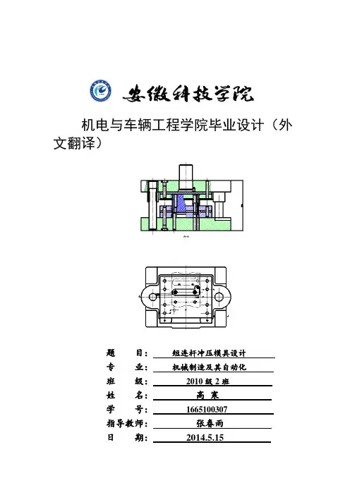
机电与车辆工程学院毕业设计(外文翻译)题目:短连杆冲压模具设计专业:机械制造及其自动化班级:2010级2班*名:**学号:**********指导教师:***日期:2014.5.15Die historyAbstract: the mold is a tool for mass production with the form of a product, is the main process equipment in industrial production. Mold has become an importantmeans of modern industrial production and technology development direction. Thefoundation of the modern economy industry. Modern industrial development andthe improvement of technical level, to a large extent depends on the developmentlevel of mold industry, so die industry to national economy and social developmentwill play an more and more important role. In order to adapt to the user for mouldmanufacturing of high precision, short delivery time, low cost, the urgent request ofthe modern advanced manufacturing technology is widely used in die and mouldindustry to accelerate the technological progress of mold industry, satisfy all walksof life to mold the base and the urgent need of process equipmentKeywords: mold; A modern economy; The development trendDie position in industrial productionMold is a high-volume products with the shape tool, is the main process of industrial production equipment.With mold components, with high efficiency, good quality, low cost, saving energy and raw materials and a series of advantages, with the mold workpieces possess high accuracy, high complexity, high consistency, high productivity and low consumption , other manufacturing methods can not match. Have already become an important means of industrial production and technological development. The basis of the modern industrial economy.The development of modern industrial and technological level depends largely on the level of industrial development die, so die industry to national economic and social development will play an increasing role. March 1989 the State Council promulgated "on the current industrial policy decision points" in the mold as the machinery industry transformation sequence of the first, production and capital construction of the second sequence (after the large-scale power generation equipment and the corresponding power transmission equipment), establish tooling industry in an important position in the national economy. Since 1997, they have to mold and its processing technology and equipment included in the "current national focus on encouraging the development of industries, products and technologies catalog" and "to encourage foreign investment industry directory." Approved by the State Council, from 1997 to 2000, more than 80 professional moldfactory owned 70% VAT refund of preferential policies to support mold industry. All these have fully demonstrated the development of the State Council and state departments tooling industry attention and support. Mold around the world about the current annual output of 60 billion U.S. dollars, Japan, the United States and other industrialized countries die of industrial output value of more than machine tool industry, beginning in 1997, China's industrial output value has exceeded the mold machine tool industry output.According to statistics, home appliances, toys and other light industries, nearly 90% of the parts are integrated with production of chopsticks; in aircraft, automobiles, agricultural machinery and radio industries, the proportion exceeded 60%. Such as aircraft manufacturing, the use of a certain type of fighter dies more than 30,000 units, of which the host 8000 sets, 2000 sets of engines, auxiliary 20 000 sets. From the output of view, since the 80's, the United States, Japan and other industrialized countries die industry output value has exceeded the machine tool industry, and there are still rising. Production technology, according to the International Association predicts that in 2000, the product best pieces of rough 75%, 50% will be finished mold completed; metals, plastics, ceramics, rubber, building materials and other industrial products, most of the mold will be completed in more than 50% metal plates, more than 80% of all plastic products, especially through the mold intoDie trendmold CAD / CAE / CAM being integrated, three-dimensional, intelligent and network direction (1) mold software features integratedDie software features of integrated software modules required relatively complete, while the function module using the same data model, in order to achieve Syndicated news management and sharing of information to support the mold design, manufacture, assembly, inspection, testing and production management of the entire process to achieve optimal benefits. Series such as the UK Delcam's software will include a surface / solid geometric modeling, engineering drawing complex geometry, advanced rendering industrial design, plastic mold design expert system,complex physical CAM, artistic design and sculpture automatic programming system, reverse engineering and complex systems physical line measurement systems. A higher degree of integration of the software includes: Pro / ENGINEER, UG and CATIA, etc.. Shanghai Jiaotong University, China with finite element analysis of metal plastic forming systems and Die CAD / CAM systems; Beijing Beihang Haier Software Ltd. CAXA Series software; Jilin Gold Grid Engineering Research Center of the stamping die mold CAD / CAE / CAM systems .(2) mold design, analysis and manufacture of three-dimensionalTwo-dimensional mold of traditional structural design can no longer meet modern technical requirements of production and integration. Mold design, analysis, manufacturing three-dimensional technology, paperless software required to mold a new generation of three-dimensional, intuitive sense to design the mold, using three-dimensional digital model can be easily used in the product structure of CAE analysis, tooling manufacturability evaluation and CNC machining, forming process simulation and information management and sharing. Such as Pro / ENGINEER, UG and CATIA software such as with parametric, feature-based, all relevant characteristics, so that mold concurrent engineering possible. In addition, Cimatran company Moldexpert, Delcam's Ps-mold and Hitachi Shipbuilding of Space-E/mold are professional injection mold 3D design software, interactive 3D cavity, core design, mold base design configuration and typical structure . Australian company Moldflow realistic three-dimensional flow simulation software MoldflowAdvisers been widely praised by users and applications. China Huazhong University of Science have developed similar software HSC3D4.5F and Zhengzhou University, Z-mold software. For manufacturing, knowledge-based intelligent software function is a measure of die important sign of advanced and practical one. Such as injection molding experts Cimatron's software can automatically generate parting direction based parting line and parting surface, generate products corresponding to the core and cavity, implementation of all relevant parts mold, and for automatically generated BOM Form NC drilling process, and can intelligently process parameter setting, calibration and other processing results.(3) mold software applications, networking trendWith the mold in the enterprise competition, cooperation, production and management, globalization, internationalization, and the rapid development of computer hardware and softwaretechnology, the Internet has made in the mold industry, virtual design, agile manufacturing technology both necessary and possible. The United States in its "21st Century Manufacturing Enterprise Strategy" that the auto industry by 2006 to achieve agile manufacturing / virtual engineering solutions to automotive development cycle shortened from 40 months to 4 months.mold testing, processing equipment to the precise, efficient, and multi-direction(1) mold testing equipment more sophisticated, efficientSophisticated, complex, large-scale mold development, testing equipment have become increasingly demanding. Precision Mould precision now reached 2 ~ 3μm, more domestic manufacturers have to use Italy, the United States, Japan and other countries in the high-precision coordinate measuring machine, and with digital scanning. Such as Dongfeng Motor Mould Factory not only has the capacity 3250mm × 3250mm Italian coordinate measuring machine, also has a digital photography optical scanner, the first in the domestic use of digital photography, optical scanning as a means of spatial three-dimensional access to information, enabling the establishment from the measurement of physical → model output of engineering drawings → → the whole process of mold making, reverse engineering a successful technology development and applications. This equipment include: second-generation British Renishaw high-speed scanners (CYCLON SERIES2) can be realized and contact laser probe complementary probe, laser scanner accuracy of 0.05mm, scanning probe contact accuracy of 0.02 mm. Another German company GOM ATOS portable scanners, Japan Roland's PIX-30, PIX-4 desktop scanner and the United Kingdom Taylor Hopson's TALYSCAN150 multi-sensor, respectively Three-dimensional scanner with high speed, low-cost and functional composite and so on.(2) CNC EDMJapan Sodick linear motor servo drive using the company's AQ325L, AQ550LLS-WEDM have driven fast response, transmission and high positioning accuracy, the advantages of small thermal deformation. Switzerland Chanmier company NCEDM with P-E3 adaptive control, PCE energy control and automatic programming expert systems. Others also used the powder mixed EDM machining technology, micro-finishing pulse power and fuzzy control (FC) technologies.(3) high-speed milling machine (HSM)Milling is an important means of cavity mold. The low-temperature high-speed milling with the workpiece, cutting force is small, smooth processing, processing quality, processing efficiency (for the general milling process 5 to 10 times) and can process hard materials (<60HRC) and many other advantages. Thus in the mold processing more and more attention. Ruishikelang company UCP710-type five-axis machining center, machine tool positioning accuracy up to 8μm, home-made closed-loop vector control spindle with a maximum speed 42000r/min. Italy RAMBAUDI's high-speed milling, the processing range of up to 2500mm × 5000mm × 1800mm, speed up 20500r/min, cutting feed speed of 20m/min. HSM generally used large, medium-sized mold, such as motor cover mold, die casting mold, large plastic surface machining, the surface precision up to 0.01mm.rapid economic modeling techniquesShorten the product development cycle is an effective means of market competition to win one. Compared with the traditional mold process, fast economic modeling technology is a short molding cycle, the characteristics of low cost, precision, and life can meet the production needs, overall economic efficiency is more significant in the mold manufacturing technology, specifically the following main technology.(1) rapid prototyping and manufacturing (RPM). It consists of three-dimensional laser lithography (SLA); laminated profile manufacturing (LOM); laser powder sintering prototyping (SLS); Fused Deposition Molding (FDM) and three-dimensional printing forming technology (3D-P) and so on.(2) the surface forming tooling. It refers to the use of spray, chemical corrosion, electroforming and new method for the formation of the cavity surface and a fine pattern technology.(3) Casting forming tooling. There are bismuth tin alloy tooling, zinc alloy tooling, resin composite forming technology and silicon rubber mold molding technology.(4) cold extrusion mold technology and ultra-molded shapes.(5) multi-point forming technology.(6) KEVRON steel blanking blanking tooling.(7) mold blank rapid manufacturing technology. Mainly dry sand Mold Casting, Vacuum MoldCasting, Resin Sand Mold Casting Lost Wax Casting, and other technologies.(8) Other aspects of technology. Such as the use of nitrogen gas spring pressure side, discharge, quick die technology, stamping unit technology, and cutting edge technology and solid surfacing edge inserts die casting technology.mold materials and surface treatment technology developed rapidlyIndustry to the level of mold, material application is the key. Due to improper selection and use of materials, causing premature die failure, which accounts for more than 45% failure die. In the mold material, commonly used cold work tool steel with CrWMn, Cr12, Cr12MoV and W6Mo5Cr4V2, flame hardened steel (such as Japan, AUX2, SX105V (7CrSiMnMoV), etc.; used a new type of hot work die steel American H13, Sweden QRO80M, QRO90SUPREME, etc.; used a pre-hardened plastic mold steel (such as the U.S. P20), age-hardening steel (such as the U.S. P21, Japan NAK55, etc.), heat treatment hardened steel (such as the United States, D2, Japan, PD613, PD555, Sweden wins the White 136, etc.), powder die steel (such as Japan KAD18 and KAS440), etc.; panel drawing die used HT300, QT60-2, Mo-Cr, Mo-V cast iron, large-scale mold with HT250. more regular use of Precision Die Hard Steel Results YG20 and other alloys and carbide. in the mold surface treatment, the main trends are: the infiltration of a single element to the multi-element penetration, complex permeability (such as TD method) development; by the general diffusion to the CVD, PVD, PCVD, ion penetration , the direction of ion implantation, etc.; can use the coating are: TiC, TiN, TiCN, TiAlN, CrN, Cr7C3, W2C, etc., while heat from the air treatment means to the development of vacuum heat treatment. In addition, the current strengthening of the laser, glow plasma Nitriding and electroplating (plating) enhanced anti-corrosion technologies are also more and more attention.The 21st century, in the new situation of economic globalization, with capital, are increasingly used to provide the products from the mold industry. In order to meet the user's high-precision mold manufacturing, short delivery time, the urgent demand low-cost, mold industry is extensive application of modern advanced manufacturing technology to speed up the mold industry, technological progress, to meet the basic sectors of the mold process equipment urgent needs.模具的发展摘要:模具是大批量生产同形产品的工具,是工业生产的主要工艺装备。
推荐-冲压模具英文原文和汉语翻译完整版 精品
Heat Treatment of Die and MouldOriented Concurrent Design LI Xiong,ZHANG Hong-bing,RUAN Xue—yu,LUOZhong—hua,ZHANG YanAbstract:Many disadvantages exist in the traditional die design methodwhich belongs to serial pattern. It is well known that heattreatment is highly important to the dies. A new idea of concurrentdesign for heat treatment process of die and mould was developedin order to overe the existent shortings of heat treatment process.Heat treatment CAD/CAE was integrated with concurrentcircumstance and the relevant model was built. Theseinvestigations can remarkably improve efficiency, reduce cost andensure quality of R and D for products.Key words:die design; heat treatment; mouldTraditional die and mould design,mainly by experience or semi—experience,is isolated from manufacturing process.Before the design is finalized,the scheme of die and mould is usually modified time and again,thus some disadvantages e into being,such as long development period,high cost and uncertain practical effect.Due to strong desires for precision,service life,development period and cost,modern die and mould should be designed and manufactured perfectly.Therefore more and more advanced technologies and innovations have been applied,for example,concurrent engin eering,agile manufacturing virtual manufacturing,collaborative design,etc.Heat treatment of die and mould is as important as design,manufacture and assembly because it has a vital effect on manufacture,assembly and service life.Design and manufacture of die and mould have progressed rapidly,but heat treatment lagged seriously behind them.As die and mould industry develops,heat treatment must ensure die and mould there are good state of manufacture,assembly and wear—resistant properties by request.Impertinent heat treatment can influence die and mould manufacturing such as over—hard and—soft and assembly.Traditionally the heat treatment process was made out according to the methods and properties brought forward by designer.This could make the designers of die and mould and heat treatment diverge from each other,for the designers of die and mould could not fully realize heat treatment process and materials properties,and contrarily the designers rarely understood the service environment and designing thought. These divergences will impact the progress of die and mould to a great extent. Accordingly,if the process design of heat treatment is considered in the early designing stage,the aims of shortening development period,reducing cost and stabilizing quality will be achieved and the sublimation of development pattern from serial to concurrent will be realized.Concurrent engineering takes puter integration system as a carrier,at the very start subsequent each stage and factors have been considered such as manufacturing,heat treating,properties and so forth in order to avoid the error.The concurrent pattern has dismissed the defect of serial pattern,which bring about a revolution against serial pattern.In the present work.the heat treatment was integrated into the concurrent circumstance of the die and mould development,and the systemic and profound research was performed.1 Heat Treatment Under Concurrent CircumstanceThe concurrent pattern differs ultimately from the serial pattern(see Fig.1).With regard to serial pattern,the designers mostly consider the structure and function of die and mould,yet hardly consider the consequent process,so that the former mistakes are easily spread backwards.Meanwhile,the design department rarely municates with the assembling,cost accounting and sales departments.These problems certainly will influence the development progress of die and mould and the market foreground.Whereas in the concurrent pattern,the relations among departments are close,the related departments all take part in the development progress of die and mould and have close intermunion with purchasers.This is propitious to elimination of the conflicts between departments,increase the efficiency and reduce the cost.Heat treatment process in the concurrent circumstance is made out not after blueprint and workpiece taken but during die and mould designing.In this way,it is favorable to optimizing the heat treatment process and making full use of the potential of the materials.2 Integration of Heat Treatment CAD/CAE for Die and MouldIt can be seen from Fig.2 that the process design and simulation of heat treatment are the core of integration frame.After information input via product design module and heat treatment process generated via heat treatment CAD and heat treatment CAE module will automatically divide the mesh for parts drawing,simulation temperature field microstructure analysis after heat—treatment and the defect of possible emerging (such as overheat,over burning),and then the heat treatment process is judged if the optimization is made according to the result reappeared by stereoscopic vision technology.Moreover tool and clamping apparatus CAD and CAM areintegrated into this system.The concurrent engineering based integration frame can share information with other branch.That makes for optimizing the heat treatment process and ensuring the process sound.2.1 3-D model and stereoscopic vision technology for heat treatmentThe problems about materials,structure and size for die and mould can be discovered as soon as possible by 3-D model for heat treatment based on the shape of die and mould.Modeling heating condition and phase transformation condition for die and mould during heat treatment are workable,because it has been broken through for the calculation of phase transformation thermodynamics,phase transformation kinetics,phase stress,thermal stress,heat transfer,hydrokinetics etc.For example,3-D heat —conducting algorithm models for local heating plicated impression and asymmetric die and mould,and M ARC software models for microstructuretransformation was used.puter can present the informations of temperature,microstructure and stress at arbitrary time and display the entire transformation procedure in the form of 3-D by coupling temperature field,microstructure field and stress field.If the property can be coupled,various partial properties can be predicted by puter.2.2 Heat treatment process designDue to the special requests for strength,hardness,surface roughness and distortion during heat treatment for die and mould,the parameters including quenching medium type,quenching temperature and tempering temperature and time,must be properly selected,and whether using surface quenching or chemical heat treatment the parameters must be rightly determined.It is difficult to determine the parameters by puter fully.Since puter technology develops quickly in recent decades,the difficulty with large—scale calculation has been overe.By simulating and weighing the property,the cost and the required period after heat treatment.it is not difficult to optimize the heat treatment process.2.3 Data base for heat treatmentA heat treatment database is described in Fig.3.The database is the foundation of making out heat treatment process.Generally,heat treatment database is divided into materials database and process database.It is an inexorable trend to predict the property by materials and process.Although it is difficult to establish a property database,it is necessary to establish the database by a series of tests.The materials database includes steel grades,chemical positions,properties and home and abroad grades parallel tables.The process database includes heat treatment criterions,classes,heat preservation time and cooling velocity.Based on the database,heat treatment process can be created by inferring from rules.2.4 Tool and equipment for heat treatmentAfter heat treatment process is determined,tool and equipment CAD/CAE system transfers the information about design and manufacture to the numerical control device.Through rapid tooling prototype,the reliability of tool and the clamping apparatus can be judged.The whole procedure is transferred by network,in which there is no man—made interference.3 Key Technique3.1 Coupling of temperature,microstructure,stress and propertyHeat treatment procedure is a procedure of temperature-microstructure—stress interaction.The three factors can all influence the property (see Fig.4).During heating and cooling,hot stress and transformation will e into being when microstructure changes.Transformation temperature-microstructure and temperature—microstructure—and stress-property interact on each other.Research on the interaction of the four factors has been greatly developed,but the universal mathematic model has not been built.Many models fit the test nicely,but they cannot be put into practice.Difficulties with most of models are solved in analytic solution,and numerical method is employed so that the inaccuracy of calculation exists.Even so,paring experience method with qualitative analysis,heat treatment simulation by puter makes great progress.3.2 Establishment and integration of modelsThe development procedure for die and mould involves design,manufacture,heat treatment,assembly,maintenance and so on.They should have own database and mode1.They are in series with each other by the entity—relation model.Through establishing and employing dynamic inference mechanism ,the aim of optimizing design can be achieved.The relation between product model and other models was built.The product model will change in case the cell model changes.In fact,it belongs to the relation of data with die and mould.After heat treatment model is integrated into the system,it is no more an isolated unit but a member which is close to other models in the system.After searching,calculating and reasoning from the heat treatment database,procedure for heat treatment,which is restricted by geometric model,manufacture model for die and mould and by cost a nd property,is obtained.If the restriction is disobeyed,the system will send out the interpretative warning.All design cells are connected by munication network.3.3 Management and harmony among membersThe plexity of die and mould requires closely cooperating among itemgroups.Because each member is short of global consideration for die and mould development,they need to be managed and harmonized.Firstly,each item group should define its own control condition and resource requested,and learn of the request of up-and-down working procedure in order to avoid conflict.Secondly,development plan should be made out and monitor mechanism should be established.The obstruction can be duly excluded in case the development is hindered.Agile management and harmony redound to municating information,increasing efficiency,and reducing redundancy.Meanwhile it is beneficial for exciting creativity,clearing conflict and making the best of resource.4 Conclusions(1) Heat treatment CAD/CAE has been integrated into concurrent design for die and mould and heat treatment is graphed,which can increase efficiency,easily discover problems and clear conflicts.(2) Die and mould development is performed on the same platform.When the heat treatment process is made out,designers can obtain correlative information and transfer self-information to other design departments on the platform.(3) Making out correct development schedule and adjusting it in time can enormously shorten the development period and reduce cost.References:[1] ZHOU Xiong-hui,PENG Ying-hong.The Theory and Technique of Modern Die and Mould Design and Manufacture[M].Shanghai:Shanghai Jiaotong University Press 2000(in Chinese).[2] Kang M,Park& puter Integrated Mold Manufacturing[J].Int J puter Integrated Manufacturing,1995,5:229-239.[3] Yau H T,Meno C H.Concurrent Process Planning for Finishing Milling and Dimensional Inspection of Sculptured Surface in Die and Mould Manufacturing[J].Int J Product Research,1993,31(11):2709—2725.[4] LI Xiang,ZHOU Xiong-hui,RUAN Xue-yu.Application of Injection Mold Collaborative Manufacturing System [J].JournaI of Shanghai Jiaotong University,2000,35(4):1391-1394.[5] Kuzman K,Nardin B,Kovae M ,et a1.The Integration of Rapid Prototyping and CAE in Mould Manufacturing [J].J Materials Processing Technology,20XX,111:279—285.[6] LI Xiong,ZHANG Hong—bing,RUAN Xue-yu,et a1.Heat Treatment Process Design Oriented Based on Concurrent Engineering[J].Journal of Iron and Steel Research,20XX,14(4):26—29.文献出处:LI Xiong,ZHANG Hong-bing,RUAN Xue—yu,LUO Zhong—hua,ZHANG Yan.Heat Treatment of Die and Mould Oriented Concurrent Design[J].Journal of Iron and Steel Research,20XX,13(1):40-43,74模具热处理及其导向平行设计李雄,张鸿冰,阮雪榆,罗中华,张艳摘要:在一系列方式中,传统模具设计方法存在许多缺点。
模具设计与制造专业外文翻译--冲压成形与板材冲压

模具设计与制造专业外文翻译--冲压成形与板材冲压外文原文Characteristics and Sheet Metal Forming1.The article overviewStamping is a kind of plastic forming process in which a part is produced by means of the plastic forming the material under the action of a die. Stamping is usually carried out under cold state, so it is also called stamping. Heat stamping is used only when the blank thickness is greater than 8-100mm. The blank material for stamping is usually in the form of sheet or strip, and therefore it is also called sheet metal forming. Some non-metal sheets (such as plywood, mica sheet, asbestos, leather)can also be formed by stamping.Stamping is widely used in various fields of the metalworking industry, and it plays a crucial role in the industries for manufacturing automobiles, instruments, military parts and household electrical appliances, etc.The process, equipment and die are the three foundational problems that needed to be studied in stamping.The characteristics of the sheet metal forming are as follows:(1) High material utilization(2) Capacity to produce thin-walled parts of complex shape.(3) Good interchangeability between stamping parts due to precision in shape and dimension.(4) Parts with lightweight, high-strength and fine rigidity can be obtained. (5) High productivity, easy to operate and to realize mechanization and automatization.The manufacture of the stamping die is costly, and therefore it only fits to mass production. For the manufacture of products in small batch and rich variety, the simple stamping die and the new equipment such as a stamping machining center, are usually adopted to meet the market demands.The materials for sheet metal stamping include mild steel, copper, aluminum, magnesium alloy and high-plasticity alloy-steel, etc.Stamping equipment includes plate shear punching press. The former shears plate into strips with a definite width, which would be pressed later. The later can be used both in shearing and forming.2(Characteristics of stamping formingThere are various processes of stamping forming with different working patterns and names. But these processes are similar to each other in plastic deformation. There are following conspicuous characteristics in stamping:,1,(The force per unit area perpendicular to the blank surface isnot large but is enough to cause the material plastic deformation. It is much less than the inner stresses on the plate plane directions. In most cases stamping forming can be treated approximately as that of the plane stress state to simplify vastly the theoretical analysis and the calculation of the process parameters.,2,(Due to the small relative thickness, the anti-instability capability of the blank is weak under compressive stress. As a result, the stamping process is difficult to proceed successfully without using the anti-instability device (such as blank holder). Therefore the varieties of the stamping processes dominated by tensile stress are more than dominated by compressive stress.,3,(During stamping forming, the inner stress of the blank is equal to or sometimes less than the yield stress of the material. In this point, the stamping is different from the bulk forming. During stamping forming, the influence of the hydrostatic pressure of the stress statein the deformation zone to the forming limit and the deformation resistance is not so important as to the bulk forming. In some circumstances, such influence may be neglected. Even in the case when this influence should be considered, the treating method is also different from that of bulk forming. ,4,(In stamping forming, the restrain action of the die to the blank is not severs as in the case of the bulk forming (such as die forging). In bulk forming, the constraint forming is proceeded by the die with exactly the same shape of the part. Whereas in stamping, in most cases, the blank has a certain degree of freedom, only one surface of the blank contacts with the die. In some extra cases, such as the forming of the blank on the deforming zone contact with the die. The deformation in these regions are caused and controlled by the die applying an external force to its adjacent area. Due to the characteristics of stamping deformation and mechanicsmentioned above, the stamping technique is different form the bulk metal forming:,1,(The importance or the strength and rigidity of the die in stamping forming is less than that in bulk forming because the blank can be formed without applying large pressure per unit area on its surface. Instead, the techniques of the simple die and the pneumatic and hydraulic forming are developed.2,2,(Due to the plane stress or simple strain state in comparisonwith bulk forming, more research on deformation or force and power parameters has been done. Stamping forming can be performed by more reasonable scientific methods. Based on the real time measurement and analysis on the sheet metal properties and stamping parameters, by means of computer and some modern testing apparatus, research on the intellectualized control of stamping process is also inproceeding. ,3,(It is shown that there is a close relationship between stamping forming and raw material. The research on the properties of the stamping forming, that is, forming ability and shape stability, has become a key point in stamping technology development, but also enhances the manufacturing technique of iron and steel industry, and provides a reliable foundation for increasing sheet metal quality. 3(Categories of stamping formingMany deformation processes can be done by stamping, the basic processes of the stamping can be divided into two kinds: cutting and forming.Cutting is a shearing process that one part of the blank is cut from the other. It mainly includes blanking, punching, trimming, parting and shaving, where punching and blanking are the most widely used. Forming is a process that one part of the blank has some displacement from the other. It mainly includes deep drawing, bending, local forming, bulging, flanging, necking, sizing and spinning.In substance, stamping forming is such that the plastic deformation occurs in the deformation zone of the stamping blank caused by the external force. The stress state and deformation characteristic of the deformation zone are the basic factors to decide the properties of the stamping forming. Based on the stress state and deformation characteristics of the deformation zone, the forming methods can be divided into several categories with the same forming properties and be studied systematically. The deformation zone in almost all types of stamping forming is in the plane stress state. Usually there is no force or only small force applied on the blank surface. When is assumed that the stress perpendicular to the blank surface equals to zero, two principal stresses perpendicular to each other and act on the blank surface produce the plastic deformation of the material. Due to the small thickness of the blank, it is assumed approximately the two principal stresses distribute uniformly along the thickness direction.Based on this analysis, the stress state and the deformation characteristics of the deformation zone in all kinds of stamping forming can bedenoted by the points in the coordinates of the plane principal stresses and the coordinates of the corresponding plane principal strains.4(Raw materials for stamping formingThere are a lot of raw materials used in stamping forming, and the properties of these materials may have large difference. The stamping forming can be succeeded only by determining the stamping method, the forming parameters and the die structures according to the properties and characteristics of the raw materials. The deformation of the blank during stamping forming has been investigated quite thoroughly. The relationships between the material properties decided by the chemistry component and structure of the material and the stamping forming has been established clearly. Not only the proper material can be selected based on the working condition and usage demand, but also the new material can be developed according to the demands of the blank properties during processing the stamping part. This is an important domain in stamping forming research. The research on the material properties for stamping forming is as follows:efinition of the stamping property of the material. ,1,(D,2,(Method to judge the stamping property of the material, find parameters to express the definitely material property of the stampingforming, establish the relationship between the property parameters and the practical stamping forming, and investigate the testing methods of the property parameters.,3,(Establish the relationship among the chemical component, structure, manufacturing process and stamping property.The raw materials for stamping forming mainly include various metals and nonmetal plate. Sheet metal includes both ferrous and nonferrous metals. Although a lot of sheet metals are used in stamping forming, the most widely used materials are steel, stainless steel, aluminum alloy and various composite metal plates. 5(Stamping forming property of sheet metal and its assessing method The stamping forming property of the sheet metal is the adaptation capability of the sheet metal to stamping forming. It has crucial meaning to the investigation of the stamping forming property of the sheet metal. In order to produce stamping forming parts with most scientific, economic and rational stamping forming process and forming parameters, it is necessary to understand clearly the properties of the sheet metal, so as to utilize thepotential of the sheet metal fully in the production. On the other hand, to select plate material accurately and rationally in accordance with the 4characteristics of the shape and dimension of the stamping forming part and its forming technique is also necessary so that a scientific understanding and accurate judgment to the stamping forming propertiesof the sheet metal may be achieved. There are direct and indirecttesting methods to assess the stamping property of the sheet metal.Practicality stamping test is the most direct method to assess stamping forming property of the sheet metal. This test is done exactly in the same condition as actual production by using the practical equipment and dies. Surely, this test result is most reliable. But this kind of assessing method is not comprehensively applicable, and cannotbe shared as a commonly used standard between factories.The simulation test is a kind of assessing method that after simplifying and summing up actual stamping forming methods, as well as eliminating many trivial factors, the stamping properties of the sheet metal are assessed, based on simplified axial-symmetric forming method under the same deformation and stress states between the testing plate and the actual forming states. In order to guarantee the reliability and generality of simulation results, a lot of factors are regulated in detail, such as the shape and dimension of tools for test, blank dimension and testing conditions(stamping velocity, lubrication method and blank holding force, etc). Indirect testing method is also called basic testing method its characteristic is to connect analysis and research on fundamental property and principle of the sheet metal during plastic deformation, and with the plastic deformation parameters of the sheet metal in actual stamping forming, and then to establish the relationship between the indirect testing results(indirect testing value) and the actual stamping forming property (forming parameters). Becausethe shape and dimension of the specimen and the loading pattern of the indirect testing are different from the actual stamping forming, the deformation characteristics and stress states of the indirect test are different from those of the actual one. So, the results obtained form the indirect test are not the stamping forming parameters, but are the fundamental parameters that can be used to represent the stamping forming property of the sheet metal.rdHans Gastrow Molds 130 Proven Designs . 3 edition . Munich : Hanser Publisher ,2002 .300-307 .中文译文冲压成形与板材冲压1(概述通过模具使板材产生塑性变形而获得成品零件的一次成形工艺方法叫做冲压。
【机械类文献翻译】冲压模具的受力分析

英文原文Stress Analysis of Stamping DiesJ. Mater. Shaping Technoi. (1990) 8:17-22 9 1990 Springer-Verlag New York Inc.R . S . R a oAbstract:Experimental and computational procedures for studying deflections, flit, andalignment characteristics of a sequence of stamping dies, housed in a transfer press, are pre-sented. Die loads are actually measured at all the 12 die stations using new load monitors and used as input to the computational procedure. A typical stamping die is analyzed using a computational code, MSC/NASTRAN, based on finite element method. The analysis is then extended to the other dies, especially the ones where the loads are high. Stresses and deflections are evaluated in the dies for the symmetric and asymmetric loading conditions. Based on our independent die analysis, stresses and deflections are found to be reasonably well within the tolerable limits. However, this situation could change when the stamping dies are eventually integrated with the press as a total system which is the ultimate goal of this broad research program.INTRODUCTIONSheet metal parts require a series of operations such as shearing , drawing , stretching , bending , and squeezing. All these operations are carried out at once while the double slide mechanism descends to work on the parts in the die stations, housed in a transfer press [1]. Material is fed to the press as blanks from a stock feeder. In operation the stock is moved from one station to the next by a mechanism synchronized with the motion of the slide. Each die is a separate unit which may be independently adjusted from the main slide. An automotive part stamped from a hot rolled steel blank in 12 steps without any intermediate anneals is shown in Figure 1.Transfer presses are mainly used to produce different types of automotive and aircraft parts and home appliances. The economic use of transfer presses depends upon quantity production as their usual production rate is 500 to 1500 parts per hour [2]. Although production is rapid in this way, close tolerances are often difficult to achieve. Moreover, the presses produce a set of conditions for off-center loads owing to the different operations being performed simultaneously in several dies during each stroke. Thus, the forming load applied at one station can affect the alignment and general accuracy of the operation being performed at adjacent stations. Another practical problem is the significant amount of set-up time involved to bring all the dies into proper operation. Hence, the broad goal of this research is to study the structural characteristics of press and dies combination as a total system. In this paper, experimental and computational procedures for investigating die problems are presented. The analysis of structural characteristics of the transfer press was pursued separately [3].A transfer press consisting of 12 die stations was chosen for analysis. Typical die problems are excessive deflections, tilt, and misalignment of the upperand lower die halves. Inadequate cushioning and offcenter loading may cause tilt and misalignment of the dies. Tilt and excessive deflections may also be caused by the lack of stiffness of the die bolster and the die itself. Part quality can be greatly affected by these die problems. There are a lot of other parameters such as the die design, friction and lubrication along the die work interface, speed, etc. that play a great role in producing consistently good parts. Realistically, the analysis should be carded out by incorporating the die design and the deforming characteristics of the work material such as the elastic-plastic work hardening properties. In this preliminary study, the large plastic deformation of the workpiece was not considered for the reasons mentioned below.Large deformation modeling of a sheet stretching process was carded out using the computational code based on an elastic-plastic work hardening model of the deformation process [4]. Laboratory experiments were conducted on various commercial materials using a hemispherical punch. The coefficient of friction along the punch-sheet interface was actually measured in the experiment and used as a prescribed boundary to the numerical model. Although a good solution was obtained, it was realized that the numerical analysis was very sensitive to the frictional conditions along the interface. In the most recent work, a new friction model based on the micromechanics of the asperity contact was developed [5]. In the present problem, there are several operations such as deep drawing, several reduction drawing operations, and coining, which are performed using complex die geometries. The resources and the duration of time were not adequate to study these nonlinear problems. Hence,the preliminary study was limited to die problems basedon linear stress analysis.A detailed die analysis was carried out by using MSC /NASTRAN code based on finite ele mentmethod. Die loads were.measured at all the stations using new load monitors. Such measured data were used in the numerical model to evaluate stresses and deflections in the dies for normal operating conditions and for asymmetric loading conditions. Asymmetric loading conditions were created in the analysis by tilting the dies. In real practice, it is customary to pursue trial-and-error procedures such as placing shims under the die or by adjusting the cushion pressure to correct the die alignment problems. Such time consuming tasks can be reduced or even eliminated using the computational and experimental procedures presented here.DIE GEOMETRY AND MATERIALSThe design of metal stamping dies is an inexact process. There are considerable trial-and-error adjustments during die tryout that are often required to finish the fabrication of a die that will produce acceptable parts. It involves not only the proper selection of die materials, but also dimensions. In order to withstand the pressure, a die must have proper cross-sectional area and clearances. Sharp comers, radii, fillets, and sudden changes in the cross section can have deleterious effects on the die life. In this work, the analysis was done on the existing set of dies.The dies were made of high carbon, high chromium tool steel. The hardness of this tool steel material is in the range of Rockwell C 57 to 60. Resistance to wear and galling was greatly improved by coating the dies with titanium nitride and titanium carbide. The dies were supported by several other steel holders made of alloy steels such as SAE 4140. The geometry of a typical stamping die is axisymmetric but it varies slightly from die to die depending on the operation. Detailed information about geometry andmaterials of a reduction drawing die (station number 4) was gathered from blueprints. It was reproducedin three-dimensional geometry using a preprocessor, PATRAN. One quadrant of the die is shown in Figure2. The data including geometry and elastic properties of the die material were fed to the numerical model.The work material used was hot rolled aluminumkilled steel, SAE 1008 A-K Steel and the blank thickness was about 4.5 ram. Stampings used in unexposed places or as parts of some deisgn where fine finish is not essential are usually made from hot rolled steel. The automotive part produced in this die set is a cover for a torque converter. A principal advantage of aluminum-killed steel is its minimum strain aging. EXPERIMENTAL PROCEDURESAs mentioned earlier, this research involved monitoting of die loads which were to be used in the numerical model to staldy the structural characteristicsof dies. The other advantage is to avoid overloadingthe dies in practice. Off-center loading can be detected and also set-up time can be reduced. Thus, any changes in the thickness of stock, dulling of the die,unbalanced loads, or overloadings can be detected using die load monitors.Strain gage based fiat load cells made of high grade tool steel material werefabricated and supplied by IDC Corporation. Four identical load cells were embedded in a thick rectangular plate as shown in Figure 3. They were calibrated both in the laboratory and in the plant.The plate was placed on the top of the die. The knockout pin slips through the hole in the plate. Six such plates were placed on each of six dies. In this way,24 readings can be obtained at a given time. Then they were shifted to the other six dies for complete data. All the 12 die loads are presented in Table 1.COMPUTATIONAL PROCEDURESLinear static analysis using finite element method wasused to study the effect of symmetric and asymmetric loading for this problem. A finite element model of diestation 4 was created using the graphical preprocessor, PATRAN, and the analysis was carried outusing the code MSC/NASTRA N . The code has a wideT a b l e I. Die LoadsDie Station LoadNumber (kN)1 3562 6413 2144 3565 8546 7127 2858 32O9 234910 113911 21412 2100spectrum of capabilities, of which linear static analysis is discussed here.The NASTRAN code initially generates a structural matrix and then the stiffness and the mass matrices from the data in the input file. The theoretical formulations of a static structural problem by the displacement method can be obtained from the references [6]. The unknowns are displacements and are solved for the appropriate boundary conditions. Strains are obtained from displacements. Then they are converted into stresses by using elastic stress-strain relationships of the die material.The solution procedure began with the creation of die geometry using the graphical preprocessor, PATRAN. The solution domain was divided into appropriate hyper-patches. This was followed by the generation of nodes, which were then connected by elements. Solid HEXA elements with eight nodes were used for this problem. The nodes and elements were distributed in such a way that a finer mesh was created at the critical region of the die-sheet metal interface and a coarser mesh elsewhere. The model was then optimized by deleting the unwanted nodes. The element connectivities were checked. By taking advantage of the symmetry, only one quarter of the die was analyzed. In the asymmetric case, half of the die was considered for analysis. Although, in practice, the load is applied at the top of the die, for the purpose of proper representation of the boundary conditions to the computational code, reaction forces were considered for analysis. The displacement and force boundary conditions are shown for the two cases inFigure 4.As mentioned earlier, sheet metal was not modeled in this preliminary research.As shown in Figure 4(a),the nodes on the top surface of the die were constrained (stationary surface) and the measured load of 356 kN was equally distributed on the contact nodes at the workpiece die interface. Similar boundary conditions for the punch are shown in Figure 4(b). It is noticeable that fewer nodes are in contact with the sheet metal due to the die tilt for the asymmetric loading case as shown in Figure 4(c). In real practice, the pressure actually varies along the die contact surface. Since the actual distribution was not known, uniform distribution was considered in the present analysis.DISCUSSION OF RESULTSAs described in the earlier section, the numerical analysis of die Station 4 (both the die and punch) was performed using the code MSC/NASTRAN . Two cases were considered, namely: (a) symmetric loading and (b) asymmetric loadingFig. 4. Boundary conditions. (A) Symmetric case (onequadrant of the die). (B) Symmetric case (one quadrant ofnthe punch). (C) Asymmetric case (half of the die). Symmetric LoadingNumerical analysis of the die was carried out for a measured load o f 356 kN as distributed equally in Figure 4(a). The major displacements in the loading direction are shown in Figure 5(a). These displacement contours can be shown in various colors to represent different magnitudes. The m aximum displacement value is 0.01 m m fora uniformly distributed load of 356 kN. The corresponding critical stress is very small,8.4 MPa in the y direction and 30 MPa in the x direction. The calculated displacements and stresses at the surrounding elements and nodes wereof the same order, but they decreased in magnitude at the nodes away from this critical region. Thus, the die was considered very rigid under this loading condition.Symmetric loading was applied to the punch and the numerical analysis was carried out separately. The displacement values in the protruding region of the punch were high compared to the die. The maximum displacement was 0.08 m m . It should be noted that the displacement values in this critical range of the punch were of the same order ranging from 0.05 mm to 0.08 ram. Although the load acting on the punch (bottom half) was the same as the die (upper half), that is, 356 kN, the values of displacements and stresses were higher in the punch because of the differences in the geometry. This is especially true for the protruding part of the punch. The corresponding maxim u m stress was 232 MPa. This part of the punch is still in the elastic range as the yield strength of tool steel is approximately 1034 MPa. The critical stress value might be varied for different load distributions. Since the actual distribution of the load was not known,the load was distributed equally on all nodes. As the die (upper half) is operating in a region which is extremely safe, a change in the load distribution may not produce any high critical stresses in the die. Although higher loads are applied at other die stations(see Table 1), it is concluded that the critical stresses are not going to be significantly higher due to the appropriate changesin the die geometries.Asymmetric LoadingFor the purpose of analysis, an asymmetric loading situation was created by tilting the die. Thus, only 15 nodes were in contact with the workpiece compared to 40 nodes for the symmetric loading case. As shown in Figure 4(c), a 356 kN load was uniformly distributed over the 15 nodes that were in contact with the workpiece. Although the pressure was high, because of the geometry at the location where the load was acting, the critical values of displacement and stress were found to be similar to the symmetric case. The predicted displacement and stress values were not significantly higher than the values predicted for the symmetric case.Fig. 5. Displacement contours in the loading direction. (A) Symmetric case (one quadrant of thedie). (B) Symmetric case (one quadrant of the punch). (C)Asymmetric case (half of the die).CONCLUSIONSIn this preliminary study, we have demonstrated the capabilities of the computational procedure, based on finite element method, to evaluate the stresses and deflections within the stamping dies for the measured loads. The dies were found to be within the tolerable elastic limits for both symmetric and asymmetric loading conditions. Thus the computational procedure can be used to study the tilt and alignment characteristics of stamping dies. In general, the die load monitors are very useful not only for analysis but also for on-line tonnage control. Future research involves theintegration of the structural analysis of stamping dies with that of the transfer press as a total system.ACKNOWLEDGMENTSProfessor J.G. Eisley, W.J. Anderson, and Mr. D.Londhe are thanked for their comments on this paper.REFERENCES1. R.S. Rao and A. Bhattacharya, "Transfer Process De-flection, Parallelism, and Alignment Characteristics,"Technical Report, January 1988, Department of Mechanical Engineering and Applied Mechanics, the University of Michigan, Ann Arbor.2. Editors of American Machinist, "Metalforming: Modem Machines, Methods, andTooling for Engineers and Operating Personnel," McGraw-Hill, Inc., 1982, pp. 47-50.3. W.J. Anderson, J.G. Eisley, and M.A. Tessmer,"Transfer Press Deflection, Parallelism, and Alignment Characteristics," Technical Report, January 1988, Department of Aerospace Engineering, the University of Michigan, Ann Arbor.4. B.B. Yoon, R.S. Rao, and N. Kikuchi, "Sheet Stretching: A Theoretical Experimental Comparison," International Journal of Mechanical Sciences, V ol. 31, No.8, pp. 579-590, 1989.5. B.B. Yoon, R.S. Rao, and N. Kikuchi, "Experimental and Numerical Comparisons of Sheet Stretching Using a New Friction Model," ASME Journal of Engineering Materials and Technology, in press.6. MSX/NASTRAN, McNeal Schwendler Corporation.22 9 J. Materials Shaping Technology, V ol. 8, No. 1, 1990。
注塑模具之模具设计与制造外文文献翻译、中英文翻译

外文翻译:Injection moulding for Mold Design and ManufactureThe mold is the manufacturing industry important craft foundation, in our country, the mold manufacture belongs to the special purpose equipment manufacturing industry. China although very already starts to make the mold and the use mold, but long-term has not formed the industry. Straight stabs 0 centuries 80's later periods, the Chinese mold industry only then drives into the development speedway. Recent years, not only the state-owned mold enterprise had the very big development, the three investments enterprise, the villages and towns (individual) the mold enterprise's development also quite rapidly.Although the Chinese mold industrial development rapid, but compares with the demand, obviously falls short of demand, its main gap concentrates precisely to, large-scale, is complex, the long life mold domain. As a result of in aspect and so on mold precision, life, manufacture cycle and productivity, China and the international average horizontal and the developed country still had a bigger disparity, therefore, needed massively to import the mold every year .The Chinese mold industry except must continue to sharpen the productivity; from now on will have emphatically to the profession internal structure adjustment and the state-of-art enhancement. The structure adjustment aspect, mainly is the enterprise structure to the specialized adjustment, the product structure to center the upscale mold development, to the import and export structure improvement, center the upscale automobile cover mold forming analysis and the structure improvement, the multi-purpose compound mold and the compound processing and the laser technology in the mold design manufacture application, the high-speed cutting, the super finishing and polished the technology, the information direction develops .The recent years, the mold profession structure adjustment and the organizational reform step enlarges, mainly displayed in, large-scale, precise, was complex, the long life, center the upscale mold and the mold standard letter development speed is higher than the common mold product; The plastic mold and the compression casting moldproportion increases; Specialized mold factory quantity and its productivity increase; "The three investments" and the private enterprise develops rapidly; The joint stock system transformation step speeds up and so on. Distributes from the area looked, take Zhujiang Delta and Yangtze River delta as central southeast coastal area development quickly to mid-west area, south development quickly to north. At present develops quickest, the mold produces the most centralized province is Guangdong and Zhejiang, places such as Jiangsu, Shanghai, Anhui and Shandong also has a bigger development in recent years.Although our country mold total quantity had at present achieved the suitable scale, the mold level also has the very big enhancement, after but design manufacture horizontal overall rise and fall industry developed country and so on Yu De, America, date, France, Italy many. The current existence question and the disparity mainly display in following several aspects:(1) The total quantity falls short of demandDomestic mold assembling one rate only, about 70%. Low-grade mold, center upscale mold assembling oneself rate only has 50% about.(2) The enterprise organizational structure, the product structure, the technical structure and the import and export structure does not gatherIn our country mold production factory to be most is from the labor mold workshop which produces assembles oneself (branch factory), from produces assembles oneself the proportion to reach as high as about 60%, but the overseas mold ultra 70% is the commodity mold. The specialized mold factory mostly is "large and complete", "small and entire" organization form, but overseas mostly is "small but", "is specially small and fine". Domestic large-scale, precise, complex, the long life mold accounts for the total quantity proportion to be insufficient 30%, but overseas in 50% above 2004 years, ratio of the mold import and export is 3.7:1, the import and export balances the after net import volume to amount to 1.32 billion US dollars, is world mold net import quantity biggest country .(3) The mold product level greatly is lower than the international standardThe production cycle actually is higher than the international water broadproduct level low mainly to display in the mold precision, cavity aspect and so on surface roughness, life and structure.(4) Develops the ability badly, economic efficiency unsatisfactory our country mold enterprise technical personnel proportion lowThe level is lower, also does not take the product development, and frequently is in the passive position in the market. Our country each mold staff average year creation output value approximately, ten thousand US dollars, overseas mold industry developed country mostly 15 to10, 000 US dollars, some reach as high as 25 to10, 000 US dollars, relative is our country quite part of molds enterprises also continues to use the workshop type management with it, truly realizes the enterprise which the modernized enterprise manages fewTo create the above disparity the reason to be very many, the mold long-term has not obtained the value besides the history in as the product which should have, as well as the most state-owned enterprises mechanism cannot adapt the market economy, but also has the following several reasons: .The mold material performance, the quality and the variety question often can affect the mold quality, the life and the cost, the domestically produced molding tool steel and overseas imports the steel products to compare has a bigger disparity. Plastic,plate, equipment energy balance, also direct influence mold level enhancement.RSP ToolingRapid Solidification Process (RSP) Tooling, is a spray forming technology tailored for producing molds and dies [2-4]. The approach combines rapid solidification processing and netshape materials processing in a single step. The general concept involves converting a mold design described by a CAD file to a tooling master using a suitable rapid prototyping (RP) technology such as stereolithography. A pattern transfer is made to a castable ceramic, typically alumina or fused silica. This is followed by spray forming a thick deposit of tool steel (or other alloy) on the pattern to capture the desired shape, surface texture and detail. The resultant metal block is cooled to room temperature and separated from the pattern. Typically, the deposit’s exterior walls are machined square, allowing it to be used as an insert in a holding block such as a MUD frame [5]. The overall turnaround time for tooling is about three days, stating with a master. Molds and dies produced in this way have been used for prototype and production runs in plastic injection molding and die casting.An important benefit of RSP Tooling is that it allows molds and dies to be made early in the design cycle for a component. True prototype parts can be manufactured to assess form, fit, and function using the same process planned for production. If the part is qualified, the tooling can be run in production as conventional tooling would. Use of a digital database and RP technology allows design modifications to be easily made.Experimental ProcedureAn alumina-base ceramic (Cotronics 780 [6]) was slurry cast using a silicone rubber master die, or freeze cast using a stereolithography master. After setting up, ceramic patterns were demolded, fired in a kiln, and cooled to room temperature. H13 tool steel was induction melted under a nitrogen atmosphere, superheated about100︒C, and pressure-fed into a bench-scale converging/diverging spray nozzle, designed and constructed in-house. An inert gas atmosphere within the spray apparatus minimized in-flight oxidation of the atomized droplets as they deposited onto the tool pattern at a rate of about 200 kg/h. Gas-to-metal mass flow ratio was approximately 0.5.For tensile property and hardness evaluation, the spray-formed material was sectioned using a wire EDM and surface ground to remove a 0.05 mm thickheat-affected zone. Samples were heat treated in a furnace that was purged with nitrogen. Each sample was coated with BN and placed in a sealed metal foil packet as a precautionary measure to prevent decarburization.Artificially aged samples were soaked for 1 hour at temperatures ranging from 400 to 700︒C, and air cooled. Conventionally heat treated H13 was austenitized at 1010︒C for 30 min., air quenched, and double tempered (2 hr plus 2 hr) at 538︒C.Microhardness was measured at room temperature using a Shimadzu Type M Vickers Hardness Tester by averaging ten microindentation readings. Microstructure of the etched (3% nital) tool steel was evaluated optically using an Olympus Model PME-3 metallograph and an Amray Model 1830 scanning electron microscope. Phase composition was analyzed via energy-dispersive spectroscopy (EDS). The size distribution of overspray powder was analyzed using a Microtrac Full Range Particle Analyzer after powder samples were sieved at 200 μm to remove coarse flakes. Sample density was evaluated by water displacement using Archimedes’ principle and a Mettler balance (Model AE100).A quasi 1-D computer code developed at INEEL was used to evaluate multiphase flow behavior inside the nozzle and free jet regions. The code's basic numerical technique solves the steadystate gas flow field through an adaptive grid, conservative variables approach and treats the droplet phase in a Lagrangian manner with full aerodynamic and energetic coupling between the droplets and transport gas. The liquid metal injection system is coupled to the throat gas dynamics, and effects of heat transfer and wall friction are included. The code also includes a nonequilibriumsolidification model that permits droplet undercooling and recalescence. The code was used to map out the temperature and velocity profile of the gas and atomized droplets within the nozzle and free jet regions.Results and DiscussionSpray forming is a robust rapid tooling technology that allows tool steel molds and dies to be produced in a straightforward manner. Each was spray formed using a ceramic pattern generated from a RP master.Particle and Gas BehaviorParticle mass frequency and cumulative mass distribution plots for H13 tool steel sprays are given in Figure 1. The mass median diameter was determined to be 56 μm by interpolation of size corresponding to 50% cumulative mass. The area mean diameter and volume mean diameter were calculated to be 53 μm and 139 μm, respectively. Geometric standard deviation, d=(d84/d16)½ , is 1.8, where d84 and d16 are particle diameters corresponding to 84% and 16% cumulative mass in Figure 1.Figure1. Cumulative mass and mass frequency plots of particles in H13 tool stepsprays.Figure2 gives computational results for the multiphase velocity flow field (Figure 2a), and H13 tool steel solid fraction (Figure2b), inside the nozzle and free jetregions. Gas velocity increases until reaching the location of the shock front, at which point it precipitously decreases, eventually decaying exponentially outside the nozzle. Small droplets are easily perturbed by the velocity field, accelerating inside the nozzle and decelerating outside. After reaching their terminal velocity, larger droplets (〜150 μm) are less perturbed by the flow field due to their greater momentum.It is well known that high particle cooling rates in the spray jet (103-106 K/s) and bulk deposit (1-100 K/min) are present during spray forming [7]. Most of the particles in the spray have undergone recalescence, resulting in a solid fraction of about 0.75. Calculated solid fraction profiles of small (〜30 μm) and large (〜150 μm) droplets with distance from the nozzle inlet, are shown in Figure 2b.Spray-Formed DepositsThis high heat extraction rate reduces erosion effects at the surface of the tool pattern. This allows relatively soft, castable ceramic pattern materials to be used that would not be satisfactory candidates for conventional metal casting processes. With suitable processing conditions, fine surface detail can be successfully transferred from the pattern to spray-formed mold. Surface roughness at the molding surface is pattern dependent. Slurry-cast commercial ceramics yield a surface roughness of about 1 μm Ra, suitable for many molding applications. Deposition of tool steel onto glass plates has yielded a specular surface finish of about 0.076 μm Ra. At the current state of development, dimensional repeatability of spray-formed molds, starting with a common master, is about ±0.2%.Figure 2. Calculated particle and gas behavior in nozzle and free jet regions.(a) Velocity profile.(b) Solid fraction.ChemistryThe chemistry of H13 tool steel is designed to allow the material to withstand the temperature, pressure, abrasion, and thermal cycling associated with demanding applications such as die casting. It is the most popular die casting alloy worldwide and second most popular tool steel for plastic injection molding. The steel has low carbon content (0.4 wt.%) to promote toughness, medium chromium content (5 wt.%) to provide good resistance to high temperature softening, 1 wt% Si to improve high temperature oxidation resistance, and small molybdenum and vanadium additions (about 1%) that form stable carbides to increase resistance to erosive wear[8]. Composition analysis was performed on H13 tool steel before and after spray forming.Results, summarized in Table 1, indicate no significant variation in alloy additions.MicrostructureThe size, shape, type, and distribution of carbides found in H13 tool steel is dictated by the processing method and heat treatment. Normally the commercial steel is machined in the mill annealed condition and heat treated(austenitized/quenched/tempered) prior to use. It is typically austenitized at about 1010︒C, quenched in air or oil, and carefully tempered two or three times at 540 to 650︒C to obtain the required combination of hardness, thermal fatigue resistance, and toughness.Commercial, forged, ferritic tool steels cannot be precipitation hardened becauseafter electroslag remelting at the steel mill, ingots are cast that cool slowly and formcoarse carbides. In contrast, rapid solidification of H13 tool steel causes alloying additions to remain largely in solution and to be more uniformly distributed in the matrix [9-11]. Properties can be tailored by artificial aging or conventional heat treatment.A benefit of artificial aging is that it bypasses the specific volume changes that occur during conventional heat treatment that can lead to tool distortion. These specific volume changes occur as the matrix phase transforms from ferrite to austenite to tempered martensite and must be accounted for in the original mold design. However, they cannot always be reliably predicted. Thin sections in the insert, which may be desirable from a design and production standpoint, are oftentimes not included as the material has a tendency to slump during austenitization or distort during quenching. Tool distortion is not observed during artificial aging ofspray-formed tool steels because there is no phase transformation.注塑模具之模具设计与制造模具是制造业的重要工艺基础,在我国,模具制造属于专用设备制造业。
冲压模具设计成型方面毕业设计外文翻译
毕业设计(论文)英文翻译课题名称系部材料工程系专业材料成型及控制工程班级学号姓名指导教师2 0 10年3 月 10日4 Sheet metal forming and blanking4.1 Principles of die manufacture4.1.1 Classification of diesIn metalforming,the geometry of the workpiece is established entirely or partially by the geometry of the die.In contrast to machining processes,ignificantly greater forces are necessary in forming.Due to the complexity of the parts,forming is often not carried out in a single operation.Depending on the geometry of the part,production is carried out in several operational steps via one or several production processes such as forming or blanking.One operation can also include several processes simultaneously(cf.Sect.2.1.4).During the design phase,the necessary manufacturing methods as well as the sequence and number of production steps are established in a processing plan(Fig.4.1.1).In this plan,the availability of machines,the planned production volumes of the part and other boundary conditions are taken into account.The aim is to minimize the number of dies to be used while keeping up a high level of operational reliability.The parts are greatly simplified right from their design stage by close collaboration between the Part Design and Production Departments in order to enable several forming and related blanking processes to be carried out in one forming station.Obviously,the more operations which are integrated into a single die,the more complex the structure of the die becomes.The consequences are higher costs,a decrease in output and a lower reliability.Fig.4.1.1 Production steps for the manufacture of an oil sumpTypes of diesThe type of die and the closely related transportation of the part between dies is determined in accordance with the forming procedure,the size of the part in question and the production volume of parts to be produced.The production of large sheet metal parts is carried out almost exclusively using single sets of dies.Typical parts can be found in automotive manufacture,the domestic appliance industry and radiator production.Suitable transfer systems,for example vacuum suction systems,allow the installation of double-action dies in a sufficiently large mounting area.In this way,for example,the right and left doors of a car can be formed jointly in one working stroke(cf.Fig.4.4.34).Large size single dies are installed in large presses.The transportation of the parts from one forming station to another is carried out mechanically.In a press line with single presses installed one behind the other,feeders or robots can be used(cf.Fig.4.4.20 to 4.4.22),whilst in large-panel transfer presses,systems equipped with gripper rails(cf.Fig.4.4.29)or crossbar suction systems(cf.Fig.4.4.34)are used to transfer the parts.Transfer dies are used for the production of high volumes of smaller and medium size parts(Fig.4.1.2).They consist of several single dies,which are mounted on a common base plate.The sheet metal is fed through mostly in blank form and also transported individually from die to die.If this part transportation is automated,the press is called a transfer press.The largest transfer dies are used together with single dies in large-panel transfer presses(cf.Fig.4.4.32).In progressive dies,also known as progressive blanking dies,sheet metal parts are blanked in several stages;generally speaking no actual forming operation takes place.The sheet metal is fed from a coil or in the form of metal ing an appropriate arrangement of the blanks within the available width of the sheet metal,an optimal material usage is ensured(cf.Fig.4.5.2 to 4.5.5). The workpiece remains fixed to the strip skeleton up until the laFig.4.1.2 Transfer die set for the production of an automatic transmission for an automotive application-st operation.The parts are transferred when the entire strip is shifted further in the work flow direction after the blanking operation.The length of the shift is equal to the center line spacing of the dies and it is also called the step width.Side shears,very precise feeding devices or pilot pins ensure feed-related part accuracy.In the final production operation,the finished part,i.e.the last part in the sequence,is disconnected from the skeleton.A field of application for progressive blanking tools is,for example,in the production of metal rotors or stator blanks for electric motors(cf.Fig.4.6.11 and 4.6.20).In progressive compound dies smaller formed parts are produced in several sequential operations.In contrast to progressive dies,not only blanking but also forming operations are performed.However, the workpiece also remains in the skeleton up to the last operation(Fig.4.1.3 and cf.Fig.4.7.2).Due to the height of the parts,the metal strip must be raised up,generally using lifting edges or similar lifting devices in order to allow the strip metal to be transported mechanically.Pressed metal parts which cannot be produced within a metal strip because of their geometrical dimensions are alternatively produced on transfer sets.Fig.4.1.3 Reinforcing part of a car produced in a strip by a compound die setNext to the dies already mentioned,a series of special dies are available for special individual applications.These dies are,as a rule,used separately.Special operations make it possible,however,for special dies to be integrated into an operational Sequence.Thus,for example,in flanging dies several metal parts can be joined together positively through the bending of certain metal sections(Fig.4.1.4and cf.Fig.2.1.34).During this operation reinforcing parts,glue or other components can be introduced.Other special dies locate special connecting elements directly into the press.Sorting and positioning elements,for example,bring stamping nuts synchronised with the press cycles into the correct position so that the punch heads can join them with the sheet metal part(Fig.4.1.5).If there is sufficient space available,forming and blanking operations can be carried out on the same die.Further examples include bending,collar-forming,stamping,fine blanking,wobble blanking and welding operations(cf.Fig.4.7.14 and4.7.15).Fig.4.1.4 A hemming dieFig.4.1.5 A pressed part with an integrated punched nut4.1.2 Die developmentTraditionally the business of die engineering has been influenced by the automotive industry.The following observations about the die development are mostly related to body panel die construction.Essential statements are,however,made in a fundamental context,so that they are applicable to all areas involved with the production of sheet-metal forming and blanking dies.Timing cycle for a mass produced car body panelUntil the end of the 1980s some car models were still being produced for six to eight years more or less unchanged or in slightly modified form.Today,however,production time cycles are set for only five years or less(Fig.4.1.6).Following the new different model policy,the demands ondie makers have also changed prehensive contracts of much greater scope such as Simultaneous Engineering(SE)contracts are becoming increasingly common.As a result,the die maker is often involved at the initial development phase of the metal part as well as in the planning phase for the production process.Therefore,a much broader involvement is established well before the actual die development is initiated.Fig.4.1.6 Time schedule for a mass produced car body panelThe timetable of an SE projectWithin the context of the production process for car body panels,only a minimal amount of time is allocated to allow for the manufacture of the dies.With large scale dies there is a run-up period of about 10 months in which design and die try-out are included.In complex SE projects,which have to be completed in 1.5 to 2 years,parallel tasks must be carried out.Furthermore,additional resources must be provided before and after delivery of the dies.These short periods call for pre-cise planning,specific know-how,available capacity and the use of the latest technological and communications systems.The timetable shows the individual activities during the manufacturing of the dies for the production of the sheet metal parts(Fig.4.1.7).The time phases for large scale dies are more or less similar so that this timetable can be considered to be valid in general.Data record and part drawingThe data record and the part drawing serve as the basis for all subsequent processing steps.They describe all the details of the parts to be produced. The information given in theFig.4.1.7 Timetable for an SE projectpart drawing includes: part identification,part numbering,sheet metal thickness,sheet metal quality,tolerances of the finished part etc.(cf.Fig.4.7.17).To avoid the production of physical models(master patterns),the CAD data should describe the geometry of the part completely by means of line,surface or volume models.As a general rule,high quality surface data with a completely filleted and closed surface geometry must be made available to all the participants in a project as early as possible.Process plan and draw developmentThe process plan,which means the operational sequence to be followed in the production of the sheet metal component,is developed from the data record of the finished part(cf.Fig.4.1.1).Already at this point in time,various boundary conditions must be taken into account:the sheet metal material,the press to be used,transfer of the parts into the press,the transportation of scrap materials,the undercuts as well as thesliding pin installations and their adjustment.The draw development,i.e.the computer aided design and layout of the blank holder area of the part in the first forming stage–if need bealso the second stage–,requires a process planner with considerable experience(Fig.4.1.8).In order to recognize and avoid problems in areas which are difficult to draw,it is necessary to manufacture a physical analysis model of the draw development.With this model,theforming conditions of the drawn part can be reviewed and final modifications introduced,which are eventually incorporated into the data record(Fig.4.1.9).This process is being replaced to some extent by intelligent simulation methods,throughwhich the potential defects of the formed component can be predicted and analysed interactively on the computer display.Die designAfter release of the process plan and draw development and the press,the design of the die can be started.As a rule,at this stage,the standards and manufacturing specifications required by the client must be considered.Thus,it is possible to obtain a unified die design and to consider the particular requests of the customer related to warehousing of standard,replacement and wear parts.Many dies need to be designed so that they can be installed in different types of presses.Dies are frequently installed both in a production press as well as in two different separate back-up presses.In this context,the layout of the die clamping elements,pressure pins and scrap disposal channels on different presses must be taken into account.Furthermore,it must be noted that drawing dies working in a single-action press may be installed in a double-action press(cf.Sect.3.1.3 and Fig.4.1.16).Fig.4.1.8 CAD data record for a draw developmentIn the design and sizing of the die,it is particularly important to consider the freedom of movement of the gripper rail and the crossbar transfer elements(cf.Sect.4.1.6).These describe the relative movements between the components of the press transfer system and the die components during a complete press working stroke.The lifting movement of the press slide,the opening and closing movements of the gripper rails and the lengthwise movement of the whole transfer are all superimposed.The dies are designed so that collisions are avoided and a minimum clearance of about 20 mm is set between all the moving parts.4 金属板料的成形及冲裁4. 模具制造原理4.1.1模具的分类在金属成形的过程中,工件的几何形状完全或部分建立在模具几何形状的基础上的。
冲压模具类外文文献翻译、中英文翻译、外文翻译
模具工业是国民经济的基础工业,是国际上公认的关键工业,工业发达国家称之为“工业之母”。
模具成型具有效率高,质量好,节省原材料,降低产品成本等优点。
采用模具制造产品零件已成为当今工业的重要工艺手段。
模具在机械,电子,轻工,纺织,航空,航天等工业领域里,已成为使用最广泛的工业化生产的主要工艺装备,它承担了这些工业领域中60%--80%产品零件,组件和部件的加工生产。
“模具就是产品质量”,“模具就是经济效益”的观念已被越来越多的人所认识和接受。
在中国,人们已经认识到模具在制造业中的重要基础地位,认识更新换代的速度,新产品的开发能力,进而决定企业的应变能力和市场竞争能力。
在目前用薄钢板制造发动机罩盖的传统还是会持续相当一段时间,所以有必要在钢板的基础上通过利用计算机软件的功能分析零件的工艺性能(结构合理,受力,是否容易冲出破面、、、),发现现有零件的不足之处,讨论并确定改进这些不足之处,进而改善模具的设计,改良冲裁方式;最终实现产品的改良,改善产品的力学性能,外观,使用效果,和造价等等。
冲压加工是通过模具来实现的,从模具角度来看,模具生产技术水平的高低,已成为衡量一个国家产品制造水平高低的重要标志,因为模具在很大程度上决定着产品的质量、效益和新产品的开发能力。
“模具是工业生产的基础工艺装备”也已经取得了共识。
据统计,在电子、汽车、电机、电器、仪器、仪表、家电和通信等产品中,60%~80%的零部件都要依靠模具成形。
用模具生产制件所具备的高精度、高复杂程度、高一致性、高生产率和低消耗,是其他加工制造方法所不能比拟的。
同时,冲压加工也创造了巨大的价值增值,模具是“效益放大器”,用模具生产的最终产品的价值,往往是模具自身价值的几十倍、上百倍。
目前全世界模具年产值约为600亿美元,日、美等工业发达国家的模具工业产值已超过机床工业,从1997年开始,我国模具工业产值也超过了机床工业产值。
其中冲压模具在所有模具(锻造模、压铸模、注塑模等)中,无论从数量、重量或者是从价值上都位居榜首。
模具,冲压相关英语专业翻译
模具工程常用词汇die 模具figure file, chart file图档cutting die, blanking die冲裁模progressive die, follow (-on)die 连续模compound die复合模punched hole冲孔panel board镶块to cutedges=side cut=side scrap切边to bending折弯to pull, to stretch拉伸Line streching, line pulling线拉伸engraving, to engrave刻印upsiding down edges翻边to stake铆合designing, to design设计design modification设计变化die block模块folded block折弯块sliding block滑块location pin定位销lifting pin顶料销die plate, front board模板padding block垫块stepping bar垫条upper die base上模座lower die base下模座upper supporting blank上承板upper padding plate blank上垫板spare dies模具备品spring 弹簧bolt螺栓plain die简易模pierce die冲孔模forming die成型模progressive die连续模gang dies复合模shearing die剪边模riveting die铆合模pierce冲孔forming成型(抽凸,冲凸) draw hole抽孔bending折弯trim切边emboss凸点dome凸圆semi-shearing半剪stamp mark冲记号deburr or coin压毛边punch riveting冲压铆合side stretch侧冲压平reel stretch卷圆压平groove压线blanking下料stamp letter冲字(料号) shearing剪断tick-mark nearside正面压印tick-mark farside反面压印冲压名称类stamping, press冲压punch press, dieing out press冲床uncoiler & strainghtener整平机feeder送料机rack, shelf, stack料架cylinder油缸robot机械手taker取料机conveyer belt输送带transmission rack输送架top stop上死点bottom stop下死点one stroke一行程inch寸动to continue, cont.连动to grip(material)吸料location lump, locating piece, block stop 定位块reset复位smoothly顺利dent压痕scratch刮伤deformation变形filings铁削to draw holes抽孔inquiry, search for查寻to stock, storage, in stock库存receive领取approval examine and verify审核processing, to process加工delivery, to deliver 交货to return delivenry to.to send delinery backto retrn of goods退货registration登记registration card登记卡to control管制to put forward and hand in提报safe stock安全库存acceptance = receive验收to notice通知application form for purchase请购单consume, consumption消耗to fill in填写abrasion磨损reverse angle = chamfer倒角character die字模to collect, to gather收集failure, trouble故障statistics统计demand and supply需求career card履历卡to take apart a die卸下模具to load a die装上模具to tight a bolt拧紧螺栓to looser a bolt拧松螺栓to move away a die plate移走模板easily damaged parts易损件standard parts标准件breaking.(be)broken,(be)cracked 断裂to lubricate润滑common vocabulary for die engineering extension dwg展开图procedure dwg工程图die structure dwg模具结构图material材质material thickness料片厚度factor系数upward向上downward向下press specification冲床规格die height range适用模高die height闭模高度burr毛边gap间隙weight重量total wt.总重量punch wt.上模重量五金零件类inner guiding post内导柱inner hexagon screw内六角螺钉dowel pin固定销coil spring弹簧lifter pin顶料销eq-height sleeves=spool等高套筒pin销lifter guide pin浮升导料销guide pin导正销wire spring圆线弹簧outer guiding post外导柱stop screw止付螺丝located pin定位销outer bush外导套模板类top plate上托板(顶板)top block上垫脚punch set上模座punch pad上垫板punch holder上夹板stripper pad脱料背板up stripper上脱料板male die公模(凸模)feature die公母模female die母模(凹模)upper plate上模板lower plate下模板die pad下垫板die holder下夹板die set下模座bottom block下垫脚bottom plate下托板(底板)stripping plate内外打(脱料板)outer stripper外脱料板inner stripper内脱料板lower stripper下脱料板零件类punch冲头insert入块(嵌入件)deburring punch压毛边冲子groove punch压线冲子stamped punch字模冲子round punch圆冲子special shape punch异形冲子bending block折刀roller滚轴baffle plate挡块located block定位块supporting block for location定位支承块air cushion plate气垫板air-cushion eject-rod气垫顶杆trimming punch切边冲子stiffening rib punch = stinger 加强筋冲子ribbon punch压筋冲子reel-stretch punch卷圆压平冲子guide plate定位板sliding block滑块sliding dowel block滑块固定块active plate活动板lower sliding plate下滑块板upper holder block上压块upper mid plate上中间板spring box弹簧箱spring-box eject-rod弹簧箱顶杆spring-box eject-plate弹簧箱顶板bushing bolck衬套cover plate盖板guide pad导料块塑件&模具相关英文compre sion molding压缩成型flash mold溢流式模具plsitive mold挤压式模具split mold分割式模具cavity型控母模core模心公模taper锥拔leather cloak仿皮革shiver饰纹flow mark流痕welding mark溶合痕post screw insert螺纹套筒埋值self tapping screw自攻螺丝striper plate脱料板piston活塞cylinder汽缸套chip细碎物handle mold手持式模具移转成型用模具encapsulation molding低压封装成型射出成型用模具two plate两极式(模具)well type蓄料井insulated runner绝缘浇道方式hot runner热浇道runner plat浇道模块valve gate阀门浇口band heater环带状的电热器spindle阀针spear head刨尖头slag well冷料井cold slag冷料渣air vent排气道h=0.02~0.05mmw=3.2mmL=3~5mmwelding line熔合痕eject pin顶出针knock pin顶出销return pin回位销反顶针sleave套筒stripper plate脱料板insert core放置入子runner stripper plate浇道脱料板guide pin导销eject rod (bar)(成型机)顶业捧subzero深冷处理three plate三极式模具runner system浇道系统stress crack应力电裂orientation定向sprue gate射料浇口,直浇口nozzle射嘴sprue lock pin料头钩销(拉料杆)slag well冷料井side gate侧浇口edge gate侧缘浇口tab gate搭接浇口film gate薄膜浇口flash gate闸门浇口slit gate缝隙浇口fan gate扇形浇口dish gate因盘形浇口H=F=1/2t~1/5tT=2.5~3.5mmdiaphragm gate隔膜浇口ring gate环形浇口subarine gate潜入式浇口tunnel gate隧道式浇口pin gate针点浇口Φ0.8~1.0mmRunner less无浇道(sprue less)无射料管方式long nozzle延长喷嘴方式sprue浇口;溶渣accurate die casting 精密压铸 powder forming 粉末成形calendaring molding 压延成形 powder metal forging 粉末锻造cold chamber die casting 冷式压铸 precision forging 精密锻造cold forging 冷锻 press forging 冲锻compacting molding 粉末压出成形 rocking die forging 摇动锻造compound molding 复合成形 rotary forging 回转锻造compression molding 压缩成形 rotational molding 离心成形dip mold 浸渍成形 rubber molding 橡胶成形6vaggh - 2007-01-15 10:58encapsulation molding 注入成形 sand mold casting 砂模铸造extrusion molding 挤出成形 shell casting 壳模铸造foam forming ?泡成形 sinter forging 烧结锻造forging roll 轧锻 six sides forging 六面锻造gravity casting 重力铸造 slush molding 凝塑成形hollow(blow) molding 中空(吹出)成形 squeeze casting 高压铸造hot chamber die casting 热室压铸 swaging 挤锻hot forging 热锻 transfer molding 转送成形injection molding 射出成形 warm forging 温锻investment casting 精密铸造 matched die method 对模成形法laminating method 被覆淋膜成形 low pressure casting 低压铸造lost wax casting 脱蜡铸造 matched mould thermal forming 对模热成形模7vaggh - 2007-01-15 10:58各式模具分类用语bismuth mold 铋铸模 landed plunger mold 有肩柱塞式模具burnishing die 挤光模 landed positive mold 有肩全压式模具button die 镶入式圆形凹模 loading shoe mold 料套式模具center-gated mold 中心浇口式模具 loose detail mold 活零件模具chill mold 冷硬用铸模 loose mold 活动式模具clod hobbing 冷挤压制模 louvering die 百叶窗冲切模composite dies 复合模具 manifold die 分歧管模具counter punch 反凸模 modular mold 组合式模具8vaggh - 2007-01-15 10:58double stack mold 双层模具 multi-cavity mold 多模穴模具electroformed mold 电铸成形模 multi-gate mold 复式浇口模具expander die 扩径模 offswt bending die 双折冷弯模具extrusion die 挤出模 palletizing die 叠层模family mold 反套制品模具 plaster mold 石膏模blank through dies 漏件式落料模 porous mold 通气性模具duplicated cavity plate 复板模 positive mold 全压式模具fantail die 扇尾形模具 pressure die 压紧模fishtail die 鱼尾形模具 profile die 轮廓模flash mold 溢料式模具 progressive die 顺序模gypsum mold 石膏铸模 protable mold 手提式模具hot-runner mold 热流道模具 prototype mold 雏形试验模具ingot mold 钢锭模 punching die 落料模lancing die 切口模 raising(embossing) 压花起伏成形re-entrant mold 倒角式模具 sectional die 拼合模runless injection mold 无流道冷料模具 sectional die 对合模具9vaggh - 2007-01-15 10:59segment mold 组合模 semi-positive mold 半全压式模具shaper 定型模套 single cavity mold 单腔模具solid forging die 整体锻模 split forging die 拼合锻模split mold 双并式模具 sprueless mold 无注道残料模具squeezing die 挤压模 stretch form die 拉伸成形模sweeping mold 平刮铸模 swing die 振动模具three plates mold 三片式模具 trimming die 切边模unit mold 单元式模具 universal mold 通用模具unscrewing mold 退扣式模具 yoke type die 轭型模10vaggh - 2007-01-15 10:59模具厂常用之标准零配件air vent vale 通气阀 anchor pin 锚梢angular pin 角梢 baffle 调节阻板angular pin 倾斜梢 baffle plate 折流档板ball button 球塞套 ball plunger 定位球塞ball slider 球塞滑块 binder plate 压板blank holder 防皱压板 blanking die 落料冲头bolster 上下模板 bottom board 浇注底板bolster 垫板 bottom plate 下固定板bracket 托架 bumper block 缓冲块buster 堵口 casting ladle 浇注包casting lug 铸耳 cavity 模穴(模仁)cavity retainer plate 模穴托板 center pin 中心梢clamping block 锁定块 coil spring 螺旋弹簧cold punched nut 冷冲螺母 cooling spiral 螺旋冷却栓core 心型 core pin 心型梢cotter 开口梢 cross 十字接头cushion pin 缓冲梢 diaphragm gate 盘形浇口11vaggh - 2007-01-15 10:59die approach 模头料道 die bed 型底die block 块形模体 die body 铸模座die bush 合模衬套 die button 冲模母模die clamper 夹模器 die fastener 模具固定用零件die holder 母模固定板 die lip 模唇die plate 冲模板 die set 冲压模座direct gate 直接浇口 dog chuck 爪牙夹头dowel 定位梢 dowel hole 导套孔dowel pin 合模梢 dozzle 辅助浇口dowel pin 定位梢 draft 拔模锥度draw bead 张力调整杆 drive bearing 传动轴承ejection pad 顶出衬垫 ejector 脱模器ejector guide pin 顶出导梢 ejector leader busher 顶出导梢衬套ejector pad 顶出垫 ejector pin 顶出梢ejector plate 顶出板 ejector rod 顶出杆ejector sleeve 顶出衬套 ejector valve 顶出阀eye bolt 环首螺栓 filling core 椿入蕊film gate 薄膜形浇口 finger pin 指形梢finish machined plate 角形模板 finish machined round plate 圆形模板12vaggh - 2007-01-15 10:59fixed bolster plate 固定侧模板 flanged pin 带凸缘?flash gate 毛边形浇口 flask 上箱floating punch 浮动冲头 gate 浇口gate land 浇口面 gib 凹形拉紧?goose neck 鹅颈管 guide bushing 引导衬套guide pin 导梢 guide post 引导柱guide plate 导板 guide rail 导轨head punch 顶?冲头 headless punch 直柄冲头heavily tapered solid 整体模蕊盒 hose nippler 管接头impact damper 缓冲器 injection ram 压射柱塞inlay busher 嵌入衬套 inner plunger 内柱塞inner punch 内冲头 insert 嵌件insert pin 嵌件梢 king pin 转向梢king pin bush 主梢衬套 knockout bar 脱模杵land 合模平坦面 land area 合模面leader busher 导梢衬套 lifting pin 起模顶?lining 内衬 locating center punch 定位中心冲头locating pilot pin 定位导梢 locating ring 定位环lock block 压块 locking block 定位块locking plate 定位板 loose bush 活动衬套making die 打印冲子 manifold block 歧管档块master plate 靠模样板 match plate 分型板mold base 塑胶模座 mold clamp 铸模紧固夹mold platen 模用板 moving bols13vaggh - 2007-01-15 11:00parallel block 平行垫块 paring line 分模线parting lock set 合模定位器 pass guide 穴型导板peened head punch 镶入式冲头 pilot pin 导?pin gate 针尖浇口 plate 衬板pre extrusion punch 顶挤冲头 punch 冲头puncher 推杆 pusher pin 衬套梢rack 机架 rapping rod 起模杆re-entrant mold 凹入模 retainer pin 嵌件梢retainer plate 托料板 return pin 回位梢riding stripper 浮动脱模器 ring gate 环型浇口roller 滚筒 runner 流道runner ejector set 流道顶出器 runner lock pin 流道拉梢screw plug 头塞 set screw 固定螺丝shedder 脱模装置 shim 分隔片shoe 模座之上下模板 shoot 流道shoulder bolt 肩部螺丝 skeleton 骨架slag riser 冒渣口 slide(slide core) 滑块slip joint 滑配接头 spacer block 间隔块spacer ring 间隔环 spider 模蕊支架spindle 主轴 sprue 注道sprue bushing 注道衬套 sprue bushing guide 注道导套sprue lock bushing 注道定位衬套 sprue puller 注道拉料? 14vaggh - 2007-01-15 11:00spue line 合模线 square key 方键square nut 方螺帽 square thread 方螺纹stop collar 限位套 stop pin 止动梢stop ring 止动环 stopper 定位停止梢straight pin 圆柱? stripper bolt 脱料螺栓stripper bushing 脱模衬套 stripper plate 剥料板stroke end block 行程止梢 submarine gate 潜入式浇口support pillar 支撑支柱/顶出支柱 support pin 支撑梢supporting plate 托板 sweep templete 造模刮板tab gate 辅助浇口 taper key 推拔键taper pin 拔锥梢/锥形梢 teeming 浇注three start screw 三条螺纹 thrust pin 推力销tie bar 拉杵 tunnel gate 隧道形浇口vent 通气孔 wortle plate 拉丝模板。
模具外文翻译--冲压成形的研究方法-其他专业
英文资料Methods to study stamping formingThe objective of the stamping forming research is to realize and apply the principles to solve various engineering problems through study on the stamping forming procedure. Recently, the research on stamping has been carried out in wide range with various methods. The research can be summed up substantially into following types.The double line arrows in the picture denote the procedure of formal theoretical research. In such research, the actions of the equipment and die are decomposed into micro-ingredients of the force and applied on the microstructure of the metal according to the multi-crystal microstructure of the deformation metal, the deformation of the metal microstructure is then investigated and the deformation of the microstructure to macro-deformation of the sheet metal is summed up. This scientific method is perfect, but current development in mechanics and metallurgy cannot meet such demand, therefore this kind of formal theoretical research is still in burgeoning, and is not applicable in practice.Since the formal theoretical research method encounters formidable difficulty, a kind of simplified theoretical method appears in the research field of the stamping forming. The characteristic of this kind of research method is denoted by continuous line in the picture, which is the main trend of the recent research. This research assumes metal as the ideal homogeneous solid and simplifies the property parameters, the boundary conditions and the blank geometrical parameters of the metal, the stamping process and principle are analyzed and described by mathematical method. Naturally, the assumptions adopted in the analysis would induce some deviation between the real stamping process and its simulation. The result is certainly approximate and does not reflect the real stamping process completely. Especially in analyzing complex stamping forming, this theory is not so valid. In recent years, due to the development of the finite element method and computer technology, this kind of theoretical method has greatly progressed, it shows applicable prospect even in analyzing complex stamping forming. The application of this kind of theoretical method mainly focuses on some special stamping deformation investigation, and it is expected that more achievements can be obtained in the fundamental principle of stamping forming. On the other hand, due to the simplification and assumptions, experiments are indispensable to test the validity of this theory.The third method to study stamping forming is shown by dashed dotted line in the picture. The characteristic of this method is that ignoring the deformation process of the blank under the action of the load during stamping forming conditions (including the structure of the die, the geometrical parameters of the die working portion and the properties of the stamping equipment) with the final results of the stamping forming. It is a rational empirical method, and widely used in stamping technology filed in recent years. This method is intuitional, simple and easy to be adopted by engineers, but it cannot be used to reveal the real procedure of the stamping deformation, so it is not the radical method to investigate the principles of the stamping forming more thoroughly and its usage is strictly limited.The fourth method to study stamping forming is denoted by dashed line in thepicture. Based on the fundamental knowledge of the mechanics and metallurgy, the essential characteristics and principle of the stamping forming are investigated to solve the practical problems in stamping process. In comparison with other plastic processes, the characteristics of the stamping forming, the principles of the sheet metal deformation are unique. So this method has definitely aim and the analysis results can be used directly to solve different problems in stamping forming. The characteristics and effects of this research of this research of this research method are illustrated by following examples.(1)The sequence of the stamping process can be decided by the trend rule of the stamping deformation.(2)According to the rule of uniform velocity distribution in the outer flange of the deformation zone during multi-pass deep drawing for the box parts, the shape and dimension of the blank during process sequence can be calculated. Therefore the calculation the for deep box parts of the multi-pass deep drawing technology is based on scientific foundation to improve the technique level of stamping forming.(3)According to the research on the wrinkle during the sheet metal forming caused by non-uniform tensile and shearing force, a new research field is developed beyond the traditional compressive instability theory. The results obtained offer an effective measure to cope directly with wrinkle during stamping forming.(4)The theory of sorting stamping forming based on the characteristics of the stamping deformation and mechanics and mechanics is an easy approach to systematize of the stamping forming, and can be used to deepen the investigation on stamping forming limit, to point out a clear and definite direction for improve the stamping forming limit.Above examples indicate that this method is closely relevant to the real stamping forming process. It can be used to analyze and solve the stamping forming problems effectively. Although this method is in the junior stage, mainly focusing on the qualitative analysis for stamping forming now . With the constant progress of this method and combined with modern mechanics, the breakthrough of this method isexpected to further enhance stamping forming technology.Structural design of blanking diel. Principle and general procedure of die designingThe steps of die designing include collecting necessary data, determining the structure scheme based on sufficient analysis and investigation, drawing the working principle diagram, the final assembly diagram, and then drawing the part diagram of the die according to the final assembly diagram.The necessary data to be collected include: the parts drawing of the product, the productive batch of the product, the process chart, the process specification and the die design program. The manufacture datum of each operation, the types of the die structural (simple die, progressive die or compound die) , the capacity of the press, the quality of the blanking work piece and other necessary items should be record in the process chart and the process specification.The detailed structure and dimension of the die are determined according to the production batch and work piece demand, etc. For the small batch production, the structure of die should be simple, the manufacture period should be short, and the cost should be as low as possible. For the large batch, the perfect structure, high productivity and long working life should be pursued.Furthermore, the structure measures to adjust, utilize, maintain, transport and deposit the dies should be taken into account.2. Determination of the pressure center of dieThe acting point of the resultant force in blanking is called the pressure center of die. In order to guarantee the die to work smoothly, the pressure center of die should align with the axes of shank and the center line of the slide block of press, to prevent the deflection of die during working, which would result in non-uniform clearance and wearing. Usually, the pressure center of die is laid on its symmetrical center point. The determination of the pressure center of die is mainly for the complex, multi-punch punching and progressive dies.For the work piece with complex shape, it can be divided into straight-linesection (the pressure center of die is situated at the middle of the straight) and arc section, and then to calculate its pressure center.The method to find the resultant force of the parallel force system is usually adopted to obtain the pressure center of die. The procedure to obtain the pressure center of die for multi-punch blanking by analytic method is showns chematically in .(1) Draw the outline of the working portion of punch proportionally.(2) Select the co-ordinate X-Y. The selection of the co-ordinate should simplify the calculation.(3)calculate the perimeter of each graphic outline (or linear section)L1,L2,L3,L4,..., L n(representing the blanking force), and the distance of gravity center in each graphic outline to the coordinate axes x1, x2, x3, x4, ...,x n and y1,y2,y3,y4,...,y n.(4) According to the mechanic principle that "the moment of the resultant force to a certain axis is equal to the sum of the moment of each component to the same axis", the calculation equation of the distance from the die pressure center to the axes of X and Y can be obtained:x0=L1x1+L2x2+L3x3+⋯+L n x n(3-20)L1+L2+L3+⋯+L n(3-21) y0=L1y1+L2y2+L3y3+⋯+L n y nL1+L2+L3+⋯+L nThe determination of the pressure center of die can also be obtained graphically by the linear polygon method.3. Determination of the shut height of dieThe outline dimension of die should fit with the selected example,the lower die of the blanking should be able to install in the working table of the press,the dimension of the shank should be consistent with that of the hole in the slide block,the ejecting pin of the ejecting device in the lower die should be able to penetrate through the bolster hole of press. The shut height of die should be consistent with that of the press.The shut height of die refers to the distance H between the top surface of the upper bolster and bottom surface of the lower bolster when the die is in the lowest working position. The shut height of press refers to the distance between the lower surface of the slide block and the upper surface of the bolster installed in the working bable when the slide block is in the lower dead point. The height when the length of the connecting rod is adjusted to the shortest, is called the maximum shut height H max; the height when the length of the connecting rod is adjusted to the longest, is called the minimum shut height H min, as shown schematically in . The shut height of die is between the maximum and minimum shut height of press, usually:If the shut height of die is larger than the maximum height of press, the die cannot be used in this press; oppositely, if the shut height of die is less than the minimum height, the die can be used by adding a bolster.中文翻译冲压成形的研究方法冲压成形的研究工作,就是在正确而深入地了解冲压成形过程的基础上,认识冲压成形过程中的各种规律性的内容,并把它运用于解决冲压生产中出现的各种实际问题。