电磁流量转换器L_Mag511中文说明书
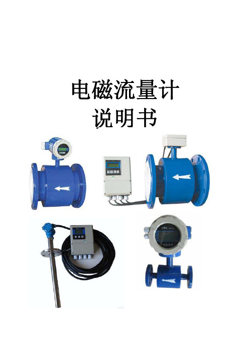
电磁流量计说明书
电磁流量计说明书目录一、产品概述二、工作原理三、产品特点四、外形尺寸五、流量选型及安装六、流量计接线图七、按键说明与菜单调试八、故障分析与排除九、电磁流量计电极内衬选择表一、产品概述智能电磁流量计是我公司采用先进技术研制、开发与生产的液体流量测量仪表,具有高精度、高可靠性与使用寿命k等优点。
为确保产品质量,我公司在设计产品结构、选材、制定工艺、生产装配与出厂测试等过程中,对每个环节细致研究与控制,并配套完整的流量标定检测系统。
产品执行标准:JB/T 9428-1999。
二、工作原理智能电磁流量计测量原理是基于法拉第电磁感应定律。
即当导电液体流过电磁流量计时,导体液体中会产牛与平均流速V(体积流量)成正比的电压,其感应电压信号通过两个与液体接触的电极检测,通过电缆传至放大器,然后转换成统一的输出信号。
基于电磁流量计的测量原理,要求流动的液体具有最低限度的电导率。
图1:结构原理图E=KBDK:比例常数B:磁感应强度D:测量管内径V:测量管截面的平均流速图2:信号流程图三、产品特点★低频三值矩形波恒流励磁,不受工频及现场各种杂散干扰的影响,性能稳定可靠。
★采用非均匀磁场的新技术及特殊磁路结构,磁场稳定可靠,且缩小了体积,减轻了重量,使流量计具有小型轻量化的特点。
★具有空管自动检测与电路处理功能。
★可根据用户实际需求现场在线修改量程。
★测量管内无阻流件,因此无附加压力损失。
★测量结果与液体的压力、温度、密度、粘度、电导率(小小于最低电导率)等物理参数无关。
★直管段相对要求较短★使用方便,安装后只需接上电源,不需其它任何操作,即可输出标准信号,便于非专业人员使用。
性能数据衬里及公称通径DN(mm):橡胶衬电:40,50,65,80,100,125,150,200,250,300,350,400,450,500,600,700,800. 900. 1000. 1200. 1400, 1600. 1800. 2000. 2200四氟衬里:10,15,20,25,32,40,50,65,80,100,125,150,200,250,300,350,400, 450. 500. 600. 700. 800. 900. 1000. 1200, 1400. 1600, 1800. 2000. 2200 注:特殊规格可订制测量误差:±0.5%、±1.0%、±1.5.被测介质温度:氯橡胶衬咀:-20℃~+65℃,聚四氟乙烯:-30℃~+180℃,聚氯脂橡胶:-20℃~+80℃,聚丙烯:-20℃~ +100℃环境温度:-25 ~+45℃相对湿度:5% - 95%额定压力:DN10-DN80: 4.0MPa DN100-DN150: 1 .6MPa DN200-DN1000: 1 .0Mpa DN1200-DN2000: 0.6MPa DN2200:0.25MPa流速范围:0. 3-12m/s电导率:被测流体电导率不小于5us/cm输出信号及负载电阻:0-10mADC,0-1000nΩ输出频率上限:l~ 5000Hz没定4-20rnADC,0-500 Ω具有防雷击保护串行通讯:可选RS232C或RS485脉冲输出上限5000CP/S;脉冲当量为0.0001~1.0 m3/CP;脉冲宽度:自动设置20ms或方波电级材料:含不锈钢(M02Ti)、钛(Ti)、钽(Ta)、哈氏合金(HB)、铀(Pt)防护等级:标准IP65、IP67、可选IP68直管段长度:上游≥10DN,下游≥5DN连接方式:管道法兰连接,符合标准:GB9119-88功耗:<25W供电电源:220V AC±10%,50HZ±5%、24VDC直流供电产品分类:管道式电磁流量计分一体型和分体型一体型分体型四、外形尺寸4.1产品的外形图34.2产品安装尺寸4.2.1平法兰型电磁流量计(含传感器的)外形及连接尺寸:(见图4、表1)图4表1平法兰型传感器连接尺寸和连接法兰安装尺寸(mm)4.2.2凹凸环槽法兰型电磁流量计(含传感器的)外形及连接尺寸(表2)表2凹凸环槽法兰型与管道连接尺寸:(mm)4.2.3螺纹连接型电磁流量计(含传感器的)外形及连接尺寸(表3)表3螺纹连接型与管道连接尺寸(mm)五、流量选型及安装如何选型正确选用电磁流量计是保证用好电磁流量计的前提条件,选用什么种类的电磁流量计应根据被测液体介质的物理性质和化学性质而决定。
电磁流量计说明书
2
PDF 文件使用 "pdfFactory Pro" 试用版本创建
◆SER 系列一体化智能型电磁流量计
二、如何正确选型
仪表的选型是应用中非常重要的工作, 首先必须根据被测流体的有关参数选择流量计的 口径、内衬和电极材料,再次根据用户对流量计的要求选择仪表外壳防护等级和输出功能, 据有关资料表明, 仪表在实际使用中有 2/3 的故障是仪表的错误选型而造成的, 请特别注意。 选型工作一般包括以下 7 个部分,即: 1、收集被测流体的有关参数 流体名称、最大/最小流量、最高压力、最高/最低温度、流体电导率、流体对仪表的磨 损性与腐蚀性、是否有回流(反向流)出现、管内是否出现负压等。
如何调看显示屏中的参数。 。 。 。 。 。 。 。 。 。 。 。 。 。 。 。 。 。 。 。 。 。 。 。 。 。 。 。 。 。6 如何由显示状态进入设定状态。 。 。 。 。 。 。 。 。 。 。 。 。 。 。 。 。 。 。 。 。 。 。 。 。 。6 如何设定测量管口径。 。 。 。 。 。 。 。 。 。 。 。 。 。 。 。 。 。 。 。 。 。 。 。 。 。 。 。 。 。 。 。 。 。6 如何设定流量量程。 。 。 。 。 。 。 。 。 。 。 。 。 。 。 。 。 。 。 。 。 。 。 。 。 。 。 。 。 。 。 。 。 。 。 。6 如何设定测量阻尼时间。 。 。 。 。 。 。 。 。 。 。 。 。 。 。 。 。 。 。 。 。 。 。 。 。 。 。 。 。 。 。 。7 如何改变流量值的正负号。 。 。 。 。 。 。 。 。 。 。 。 。 。 。 。 。 。 。 。 。 。 。 。 。 。 。 。 。 。7
上表中,最小流量与最大流量对应的流速为 0.1~15m/s 您可以根据上表中的流量范围选择合适的流量计口径,测清洁水时,经济流速是 1.5~3m/s,此时管损小,泵耗电量低;测易结晶结垢的液体时,适当提高流速,以>3m/s 为宜,流速高起到自清扫作用,从而防止液体粘附沉积在管壁和电极上;测矿浆等磨损大的 流体时,应适当降低流速,以<2m/s 为宜,以降低介质对内衬和电极的磨损。实际应用中 管道流体流速高于 7m/s 的较少,超过 10m/s 的则更为罕见。
电磁流量计使用说明书

技术资料Technical Information电磁流量计使用说明书北京多益慧元科技有限公司本仪表在出厂前已经过全面调试。
为了保证仪表的正常使用,请仔细阅读产品说明书,并在操作前充分了解如何使用该仪表。
关于本套用户说明书该套说明书必须提供给最终使用用户。
未经预先通知,产品说明书的内容可能改动。
版权所有,未经本公司书面同意,不得以任何形式复制说明书的任何部分。
本公司不对本说明书做任何形式的保证,其中包括但不限于本说明书的出售以及用于其他特殊目的。
本公司努力确保说明书的各项内容正确性,但若发现任何错误或者疏漏,请通知本公司。
除上面提到的内容以外,本公司不对本产品承担任何其他责任。
如产品规格、结构或者操作的改变不影响其运行、使用和性能,用户说明书不随之修订。
本产品说明书将协助您安装、使用和维护您的流量计。
我们的责任:确保所有使用者获得足够的安全操作和维护程序。
警告为了您的安全,请在使用仪表前认真阅读以下安全警告。
1.流体不会腐蚀仪表表体和接液部件材质。
2.当测量易燃液体,注意防范火灾或爆炸。
3.处理有害液体时,须遵循生产厂商的安全操作规范。
4.在危险的环境中工作时,须遵循正确操作步骤。
5.流量计拆除时,可能会造成液体飞溅。
请按照流体设备商的安全操作规范防止飞溅。
6.为了达到最佳效果,仪表校准周期最长不超过1年。
第一部分电磁流量转换器说明书 (1)A、通用型电磁流量转换器 (1)一、概述 (1)二、技术参数 (1)2.1通用指标 (1)2.2电气指标 (2)2.2.1普通型流量转换器 (2)2.2.2电池供电型流量转换器 (3)2.2.3过程控制型流量转换器 (5)三、安装 (6)3.1安装注意事项 (6)3.2电气接线 (6)3.2.1普通型转换器接线 (6)3.2.2电池供电型转换器接线 (10)3.2.3过程控制型转换器接线 (15)3.3主要部件及尺寸参数 (16)3.3.1普通型\过程控制型转换器安装尺寸图 (16)3.3.2电池供电型转换器安装尺寸图 (17)四、操作、使用与设置 (18)4.1普通型转换器 (18)4.2电池供电型转换器 (26)4.2.1脉冲输出参数设置 (26)4.2.2参数设置 (27)4.2.3仪表详细参数说明 (28)4.2.4仪表报警显示 (29)4.2.5非线性修正功能说明 (30)4.2.6各口径下脉冲宽度为1ms时设置参考表 (31)4.3过程控制型转换器 (32)4.3.1基本操作说明 (32)4.3.2参数一览表 (32)4.3.3仪表参数详细说明 (33)4.3.4HART通讯功能说明 (35)4.3.5带非线性修正功能补充说明 (36)B、经济型电磁流量转换器 (37)一、概述 (37)1.1应用场合 (37)1.2特点 (37)二、电气指标 (38)三、安装 (39)3.1机械连接 (39)3.2电气连接 (39)3.2.1键盘及显示面板 (39)3.2.2接线端子及电源输入 (40)3.2.3模拟量(4-20mA)输出 (41)3.2.4数字量输出 (42)3.3主要部件及尺寸参数 (45)四、操作及使用 (46)4.1操作、使用 (46)4.2参数设置 (47)4.2.1按键功能及参数设置 (47)4.2.2参数设置功能及功能键操作 (47)4.2.3功能选择 (48)4.2.4仪表详细参数说明 (50)4.2.5空管报警参数设置 (54)第二部分电磁流量传感器说明书 (55)A、管道式电磁流量传感器 (55)一、概述 (55)1.1应用场合 (55)1.2仪表特点与用途 (55)二、工作原理 (56)三、技术规格 (57)3.1技术参数 (57)3.2测量范围 (58)四、安装 (60)4.1电磁传感器尺寸参数 (60)4.1.1传感器外型尺寸 (60)4.1.2传感器的安装尺寸 (61)4.1.3电磁传感器材质 (62)4.2安装及注意事项 (64)4.2.1安装位置 (64)4.2.2安装方向 (64)4.2.3对直管段要求 (65)4.2.4安装说明 (66)B、插入式电磁流量传感器 (69)一、概述 (69)二、工作原理 (69)三、功能特点 (69)四、技术参数 (70)4.1技术规格 (70)4.2测量范围 (71)五、安装说明 (73)第三部分保修及常见故障排除 (76)一、保修 (76)二、铭牌型号与规格 (76)三、运输和贮存注意事项 (77)四、安装场所注意事项 (77)五、常见故障排除 (78)第一部分电磁流量转换器说明书A、通用型电磁流量转换器一、概述通用型智能电磁流量计由传感器和转换器两部分构成。
电磁流量计说明书
1
1.1
电磁流量计由电磁流量传感器和电磁流量转换器两大部分组成。它是根据法拉第电磁感应定律而制成的一种仪表,用于测量封闭管道中导电液体和浆液的体积流量。电磁流量计有各种输出信号供用户选择。电磁流量计应用于化工、电力、矿冶、给排水、造纸、医药、食品、环保等工业部门。
一体型电磁流量计:-25℃~+55℃
相对湿度:(5~90)%;
大气压力:(86~106)kPa.
1.4
流体电导率: 不低于5μs/cm;
公称压力: 4.0MPa DN(15、20、25、32、40、50、65、80、100、150)
1.0MPa DN(200、250、300、350、400、450、500、600、700、800、900、1000)
1.2
a.测量不受流体密度、粘度、温度、压力和电导率变化影响;
b.测量管内无阻碍流动部件,无压损,直管段要求较低。对浆液测量有独特的适应性;
c.可输出与流速成正比例的线性模拟信号或频率信号,测量范围宽;
d.采用低频方波励磁,功耗小,零点稳定。
1.3
环境温度:分体型电磁流量传感器:(-25~+55)℃ 分体型转换器:(-25~+55)℃
0.2级
0.3级
0.5级
2
DN(600、700、800、900、1000、1200、1400、1600、1800、2000、2200、2400、2600)
0.3级
0.5级
流量范围对应的流速范围:(0.5~10)m/s
测量管材质: 304
衬里材质:软橡胶、聚氨酯橡胶、聚四氟乙烯、氟化乙炳烯
电极材质:不锈钢0Cr18Ni12Mo2Ti、哈氏合金B、哈氏合金C、钛、钽
SITRANS F 电磁流量计 SITRANS FM MAG 5100 W 操作说明说明书

3.1
系统组件 ............................................................................................................................................................................................................................................ 22
1.9
保修注意事项 ................................................................................................................ 9
2 安全注意事项 ................................................................................................................................. 11
4.3
传感器定向.................................................................................................................. 29
4.4
安装 ............................................................................................................................ 30
Omega EP510, IP510, EP511, IP511系列电子流量转换器用户指南说明书

e-mail:**************For latest product manuals:EP510, IP510,EP511, IP511 SERIESElectroneumatic ConvertersShop online atUser’sGuideIt is the policy of OMEGA Engineering, Inc. to comply with all worldwide safety and EMC/EMI regulations that apply. OMEGA is constantly pursuing certification of its products to the European New Approach Directives. OMEGA will add the CE mark to every appropriate device upon certification.The information contained in this document is believed to be correct, but OMEGA accepts no liability for any errors it contains, and reserves the right to alter specifications without notice.WARNING: These products are not designed for use in, and should not be used for, human applications.AIR CONNECTIONSSUPPLYConnect air supply to 1/4 NPT port marked "IN." If the above specifications are not met, possibility of internal clogging exists. Also see MAINTENANCE section.OUTPUTConnect output to 1/4 NPT port marked "OUT."GAUGEThe plugged 1/8 NPT port in the base of the transducer is internally connected with the "OUT" port. A pressure gauge can be attached to this port to monitor output pressure.CONTENTSAir Connections . . . . . . . . . . . . . . . . . . . . . . . . . . . . . . . . . . . . . . . . . . . . . .Page 1Pressure Requirements . . . . . . . . . . . . . . . . . . . . . . . . . . . . . . . . . . . . . . . .Page 2Mounting . . . . . . . . . . . . . . . . . . . . . . . . . . . . . . . . . . . . . . . . . . . . . . . .Page 2Direct Mounting Mounting KitsElectrical Connections . . . . . . . . . . . . . . . . . . . . . . . . . . . . . . . . . . . . . . . . .Page 3Precautions to be observed during installationCalibration . . . . . . . . . . . . . . . . . . . . . . . . . . . . . . . . . . . . . . . . . . . . . . . .Page 4Maintenance . . . . . . . . . . . . . . . . . . . . . . . . . . . . . . . . . . . . . . . . . . . . . . . .Page 5Agency Approvals, Special Notes, and Cautions . . . . . . . . . . . . . . . . . .Page 5 & 6Kits . . . . . . . . . . . . . . . . . . . . . . . . . . . . . . . . . . . . . . . . . . . . . . . .Page 7Specifications . . . . . . . . . . . . . . . . . . . . . . . . . . . . . . . . . . . . . . . . . . . . . . . .Page 8WARNINGIn order to get optimal service from this transducer and ensure warranty coverage the following MUST be followed:•The supply air quality to this instrument must be instrument quality air as defined by ISA Standard 57.0.01-1996.1. Dew point not higher than 35˚F.2. No particulates larger than 3 microns in size.3. Maximum oil content of 1 ppm.• No mechanical adjustments or calibrations are necessary or allowed. All calibration MUST be done with electrical poten-tiometers on the enclosed circuit board only. See “CALIBRATION” section of instructions for more information.M-4109/1104 IP510, EP510, IP511, EP511 SERIES A3TABLE 1: SUPPLY PRESSURE REQUIREMENTSStandard Output Calibration 0-2 PSI 0-5 PSI 0-30PSI 0-60PSI0-100PSI0-120PSI1-17PSI3-9 PSI3-15PSI3-27PSI6-30PSITransducer Supply Pressure20-45PSI20-45PSI50-90PSI80-120PSI 110-130PSI 130-140PSI 30-70PSI 20-100PSI 20-100PSI 35-100PSI 35-100PSIM EP510 AND IP510OUNTINGGENERALNEMA 1 and NEMA 4X transducers can be mounted in any position.DIRECT MOUNTING PIPE• Any NEMA 1 transducers may be supported by its own plumbing for air supply and output. NEMA 4X transducers mayalso be supported using 1/2" explosion proof conduit in the electrical port.PANEL• NEMA 1 transducers may be mounted to a panel with two No. 10-32 screws using threaded holes in the back of a trans-ducer or with two to four No. 8-32 screws using threaded holes in the bottom of a transducer.• NEMA 4X transducers may be mounted to a panel with three No. 10-32 screws using threaded holes in the back of atransducer or with four No. 8-32 screws using threaded holes in the bottom of a transducer. In the case of back-mount-ing, if the panel extends towards the screw-on cover, a 3/16-inch-thick spacer MUST be used between the back of the transducer and the panel in order for the panel to clear the transducer's screw-on cover.4ELECTRICAL CONNECTIONSPRECAUTIONS TO BE OBSERVED DURING INSTALLATIONThese Transducers were tested at the EMC Test Centre, Dunfermline, Fife, KY11 5LB to the Electromagnetic Compatibility Directive effective January 1, 1996. The relevant EMC specifications tested were the following:EN 50081-1 (1992) and EN 50082-2 (1992). A Technical Construction File, Serial #107 was written and Certificate of Conformity issued by a Competent Body.EN 50081-1 (1992): Test results confirmed that no precautions need to be observed during installation regarding electro-magnetic emissions from the 510 or 511 Series Transducers.EN 50082-2 (1992): The following precautions should be taken during installation to maintain the advertised accuracy speci-fications. The input wiring to the transducer should be isolated from other high voltage transient wiring. The momentary switching on and off of nearby relays, motors, or other high capacitive or inductive loads can have a minor effect on the accuracy specification (0.25% of Span). Any change in output pressure is minimal and momentarily, and is considered to be within the performance capabilities. Use of a ferrite bead collar on the input wires entering the transducer is recommended should installation next to high electromagnetic interference be necessary.WARNING:In explosive atmospheres, electrical power must be removed from the transducer before attempting to remove the cover and until the cover is fully reinstalled. Failure to do so may result in electrical spark or explosion.CAUTION: Care must be used when inserting wires into the NPT port. Wires must not enter below the circuit board due to sensitive mechanical components.DIRECTIONS1. Remove the cover (see WARNING above).2. Bring wiring to the terminal block, located on the circuit board, through 1/2 NPT electrical conduit connection. 18A.W.G. is recommended; 14 A.W.G. is the maximum wire size. Connect wires to the terminal block per TABLE 2. Care must be exercised to prevent damage to delicate internal parts when inserting wiring through the 1/2” NPT conduit opening.3. An internal grounding screw is provided on all units to facilitate separate ground when required. An external groundinglug is also provided on NEMA 4X enclosures.4. Reinstall the cover tightly using all o-rings and locking devices to insure compliance with Agency Approvals.CALIBRATIONM-4109/1104 IP510, EP510, IP511, EP511 SERIES A5TABLE 2: ELECTRICAL CONNECTIONSTERMINAL BLOCK I / P TRANSDUCER MODELS E / P TRANSDUCER MODELS POSITION # 1( -- ) NEGATIVE SIGNAL( + ) POSITIVE SIGNAL POSITION # 2NOT USED COMMON GND FOR SIGNALAND SUPPLY POSITION # 3( + ) POSITIVE SIGNAL( + ) POSITIVE SUPPLYWARNING:In explosive atmospheres, electrical power must be removed from the transducer before attempting to remove the cover and until the cover is fully reinstalled. Failure to do so may result in electrical spark or explosion.CAUTION:Only attempt electrical adjustments as described below. Any mechanical adjustments made will void the warranty.1. Remove the cover to gain access to the "SPAN",(marked S), "FINE ZERO",(marked Z) and the "DAMPING", (3/4 turn lowprofile) potentiometers. The unmarked pot “COURSE ZERO”, is used only for major calibration range changes. This adjustment should only be attempted by factory trained personnel. For NEMA 1 enclosure, just slide open the access door on the top of the cover.2. Set electrical input signal to 0% (e.g. 4 mA or 0 VDC).3. FORWARD ACTING UNITS:Using "FINE ZERO"potentiometer, adjust output pressure to 0% output (e.g. 3 psi).4. Set electrical input signal to 100% (e.g. 20 mA or 10 VDC).5. FORWARD ACTING UNITS: Using "SPAN"potentiometer, adjust output pressure to 100% output (e.g. 15 psi).6.Repeat steps 2 through 5 until output pressures are properly set.NOTE: Under certain circumstances, output pressure may exhibit cycling action. To eliminate this condition, use the "DAMPING"potentiometer.7.Reinstall cover using original screws and gaskets, if equipped.MAINTENANCEWhen used properly, these transducers should provide more than one million cycles without failure. If a situation should occur in which the transducer's behavior is abnormal, the cause is usually related to a pneumatic problem.ELECTRICAL MAINTENANCEAn electrical problem must be isolated by a skilled technician. The power source and all wiring should be checked first.Circuit board failures are very rare, and can be confirmed by the following method. Loosen the screws, or posts that hold the circuit board in place. Unplug the blue connector from the circuit board, and insert two small pieces of wire into the con-nector.IMPORTANT: Connect a current source with the polarity as follows. Positive to the (RED) coil wire and Negative to the (BROWN)coil wire of 10 mA to the connector, which powers the yellow coil. With supply pressure on, the unit should pro-duce an output pressure equivalent to 80% or more of the maximum output pressure. If there is little or no output, then the unit is clogged. Should it produce an adequate output pressure, then the circuit board is the primary suspect. The unit must be returned to the factory for repair.PNEUMATIC MAINTENANCEAll 510 and 511 Series transducers also have an internal orifice filter, but if contaminates do invade the transducer, they can clog the internal orifice and block the flow, or jam open the internal supply valve. The problem can be corrected through replacement of the orifice (see TABLE 5: KITS) or by cleaning the internal supply valve, or both.M-4109/1104 IP510, EP510, IP511, EP511 SERIESA 6M-4109/1104 IP510, EP510, IP511, EP511 SERIES AREPLACING ORIFICE:This can be accomplished without removing the unit from its mounting or plumbing.1. Turn off supply pressure and unscrew the brass orifice assembly located on the side of the housing with the gaugeport.NOTE: Small sealing o-ring may remain inside of the housing. If it does, remove it with a paper clip or some other small probe. The replacement assembly will contain this o-ring.2. Install the new orifice assembly making sure the o-ring is seated on the end of the screw.CLEANING INTERNAL SUPPLY VALVE:1. Turn off the supply pressure.2. Use a 9/16" socket or wrench to unscrew the brass plug in the bottom of the transducer.NOTE: Take care not to lose the supply valve spring which is retained by the bottom plug.3. Clean out any dirt or debris and reassemble, making sure the stem of the supply valve is nested in the supply valvespring.AGENCY APPROVALS, SPECIAL NOTES, AND CAUTIONSINTRINSIC SAFETYAll 510 and 511 Series transducers are rated intrinsically safe by both FM and CSA for:CLASS I, DIVISION 1, GROUPS A,B,C,D HAZARDOUS LOCATIONS.Proper FM-approved intrinsically-safe wiring requires external FACTORY MUTUAL RESEARCH CORPORATION ENTITY-APPROVED SINGLE-CHANNEL barriers to be selected, based upon MAXIMUM ENTITY PARAMETERS of 510 and 511 Series transducers:ENTITY PARAMETERS:Vmax = 28 V, Imax = 150 mA, Ci = 0.22uF, Li = 0 mH.Voc and Isc of a barrier shall not exceed Vmax and Imax of the transducer.(Li + Lwiring) and (Ci + Cwiring) shall not exceed La and Ca of a barrier.NOTICE: For proper FM and CSA approved intrinsically-safe wiring, request Drawing Number 990-439-000 from the Factory.NONINCENDIVEAll 510 and 511 Series transducers are approved as NONINCENDIVE by FM and approved as suitable by CSA for: CLASS I, DIVISION 2, GROUP A, B, C, D HAZARDOUS LOCATIONS.A barrier is not necessary when these transducers are in these locations.ENCLOSURESCompliance with NEMA 4X and CSA ENC4enclosure ratings require that the screw-on cover has the O-ring installed. In case of a need for replacement parts, see TABLE 3.7EXPLOSION & DUST-IGNITION PROOF CERTIFICATIONS FACTORY MUTUAL and CANADIAN STANDARDS ASSOCIATIONWARNING:The following ratings are valid ONLY WHEN the cover is installed for FM and CSA. BOTH the cover and the locking device, using tamper resistant screws must be installed. Screws are to be removed and installed with a special driver bit (supplied). In case of a need for replacement parts, follow TABLE 4.EXPLOSION PROOF FOR CLASS I, DIV 1, GROUP B, C, D.DUST-IGNITION PROOF FOR CLASS II, DIV 1, GROUP E, F, G.SUITABLE FOR CLASS III LOCATIONS.M-4109/1104 IP510, EP510, IP511, EP511 SERIESA 8TABLE 3: NEMA 4X, REPLACEMENT COVER O-RINGS PART NAME PART NUMBER O-RING SEAL, VITON 214-649-000-242O-RING SEAL, BUNA-N 214-649-000-240TABLE 4: NEMA 4X, REPLACEMENT PARTS FOR COVER LOCKING DEVICEPART NAME PART NUMBER LOCKING CLAMP 224-669-000-016TAMPER-PROOF SCREW 214-648-000-401DRIVER BIT 010132-000EP511 AND IP51110WARRANTY/DISCLAIMEROMEGA ENGINEERING, INC. warrants this unit to be free of defects in materials and workmanship for a period of 13 months from date of purchase. OMEGA’s WARRANTY adds an additional one (1) month grace period to the normal one (1) year product warranty to cover handling and shipping time. This ensures that OMEGA’s customers receive maximum coverage on each product.If the unit malfunctions, it must be returned to the factory for evaluation. OMEGA’s Customer Service Department will issue an Authorized Return (AR) number immediately upon phone or written request.Upon examination by OMEGA, if the unit is found to be defective, it will be repaired or replaced at no charge. OMEGA’s WARRANTY does not apply to defects resulting from any action of the purchaser,including but not limited to mishandling, improper interfacing, operation outside of design limits, improper repair, or unauthorized modification. T his WARRANT Y is VOID if the unit shows evidence of having been tampered with or shows evidence of having been damaged as a result of excessive corrosion;or current, heat, moisture or vibration; improper specification; misapplication; misuse or other operating conditions outside of OMEGA’s control. Components in which wear is not warranted, include but are not limited to contact points, fuses, and triacs.OMEGA is pleased to offer suggestions on the use of its various products. However, OMEGA neither assumes responsibility for any omissions or errors nor assumes liability for any damages that result from the use of its products in accordance with information provided by OMEGA, either verbal or written. OMEGA warrants only that the parts manufactured by the company will be as specified and free of defects. OMEGA MAKES NO OTHER WARRANTIES OR REPRESENTATIONS OF ANY KIND W HATSOEVER, EXPRESSED OR IMPLIED, EXCEPT THAT OF TITLE, AND ALL IMPLIED WARRANTIES INCLUDING ANY WARRANTY OF MERCHANTABILITY AND FITNESS FOR A PARTICULAR PURPOSE ARE HEREBY DISCLAIMED. LIMITATION OF LIABILITY: The remedies of purchaser set forth herein are exclusive, and the total liability of OMEGA with respect to this order, whether based on contract, warranty, negligence, indemnification, strict liability or otherwise, shall not exceed the purchase price of the component upon which liability is based. In no event shall OMEGA be liable for consequential, incidental or special damages.CONDITIONS: Equipment sold by OMEGA is not intended to be used, nor shall it be used: (1) as a “Basic Component” under 10 CFR 21 (NRC), used in or with any nuclear installation or activity; or (2) in medical applications or used on humans. Should any Product(s) be used in or with any nuclear installation or activity, medical application, used on humans, or misused in any way, OMEGA assumes no responsibility as set forth in our basic WARRANTY /DISCLAIMER language, and, additionally, purchaser will indemnify OMEGA and hold OMEGA harmless from any liability or damage whatsoever arising out of the use of the Product(s) in such a manner.RETURN REQUESTS/INQUIRIESDirect all warranty and repair requests/inquiries to the OMEGA Customer Service Department. BEFORE RET URNING ANY PRODUCT (S) T O OMEGA, PURCHASER MUST OBTAIN AN AUT HORIZED RET URN (AR) NUMBER FROM OMEGA’S CUST OMER SERVICE DEPART MENT (IN ORDER T O AVOID PROCESSING DELAYS). The assigned AR number should then be marked on the outside of the return package and on any correspondence.The purchaser is responsible for shipping charges, freight, insurance and proper packaging to prevent breakage in transit.FOR WARRANTY RETURNS, please have thefollowing information available BEFOREcontacting OMEGA:1.Purchase Order number under which the productwas PURCHASED,2.Model and serial number of the product underwarranty, and3.Repair instructions and/or specific problemsrelative to the product.FOR NON-WARRANTY REPAIRS,consult OMEGA for current repair charges. Have the following information available BEFORE contacting OMEGA:1. Purchase Order number to cover the COST of the repair,2.Model and serial number of the product, and 3.Repair instructions and/or specific problems relative to the product.OMEGA’s policy is to make running changes, not model changes, whenever an improvement is possible. This affords our customers the latest in technology and engineering.OMEGA is a registered trademark of OMEGA ENGINEERING, INC.© Copyright 2009 OMEGA ENGINEERING, INC. All rights reserved. T his document may not be copied, photocopied,reproduced, translated, or reduced to any electronic medium or machine-readable form, in whole or in part, without theprior written consent of OMEGA ENGINEERING, INC.Where Do I Find Everything I Need for Process Measurement and Control?OMEGA…Of Course!Shop online at SMTEMPERATUREⅪߜThermocouple, RTD & Thermistor Probes, Connectors, Panels & AssembliesⅪߜWire: Thermocouple, RTD & ThermistorⅪߜCalibrators & Ice Point ReferencesⅪߜRecorders, Controllers & Process MonitorsⅪߜInfrared PyrometersPRESSURE, STRAIN AND FORCEⅪߜTransducers & Strain GagesⅪߜLoad Cells & Pressure GagesⅪߜDisplacement TransducersⅪߜInstrumentation & AccessoriesFLOW/LEVELⅪߜRotameters, Gas Mass Flowmeters & Flow ComputersⅪߜAir Velocity IndicatorsⅪߜTurbine/Paddlewheel SystemsⅪߜTotalizers & Batch ControllerspH/CONDUCTIVITYⅪߜpH Electrodes, Testers & AccessoriesⅪߜBenchtop/Laboratory MetersⅪߜControllers, Calibrators, Simulators & PumpsⅪߜIndustrial pH & Conductivity EquipmentDATA ACQUISITIONⅪߜData Acquisition & Engineering SoftwareⅪߜCommunications-Based Acquisition SystemsⅪߜPlug-in Cards for Apple, IBM & CompatiblesⅪߜData Logging SystemsⅪߜRecorders, Printers & PlottersHEATERSⅪߜHeating CableⅪߜCartridge & Strip HeatersⅪߜImmersion & Band HeatersⅪߜFlexible HeatersⅪߜLaboratory HeatersENVIRONMENTALMONITORING AND CONTROLⅪߜMetering & Control InstrumentationⅪߜRefractometersⅪߜPumps & TubingⅪߜAir, Soil & Water MonitorsⅪߜIndustrial Water & Wastewater TreatmentⅪߜpH, Conductivity & Dissolved Oxygen InstrumentsM4109/0909。
电磁流量计使用说明书
电磁流量计说明书2012资料
目录一、产品特点、用途和使用范围 (1)二、工作原理 (1)2.1 数学模型 (1)2.2 转换器电路结构 (2)三、产品型式和组成 (3)3.1 产品模式 (3)3.2 产品组成 (3)四、产品技术性能指标 (3)五、产品外形尺寸及安装尺寸 (4)5.1 转换器外形尺寸 (4)5.2 传感器外形和安装尺寸 (5)六、转换器菜单结构及参数设置 (6)6.1 按键形式 (6)6.2 按键功能 (6)6.3 参数设置功能及操作密码 (6)6.4 参数菜单一览表 (7)6.5 参数设置菜单说明 (8)6.6 掉电时间记录功能 (8)6.7 小时累计记录 (12)七、流量计安装图示 (12)八、电气接线 (14)8.1 流量计与管道的接地 (14)8.2 转换器接线端子与标示 (15)8.3 分离型接线 (16)8.4 输出信号接线图示 (17)九、自诊断信息与故障处理 (19)十、供应成套性 (20)十一、运输和贮存 (20)十二、运行 (20)附录:产品选型编码 (21)一、产品特点、用途和适用范围1.1特点·LDG系列电磁流量计,具有以下特点:·不受流体密度、粘度、温度、压力和电导率变化的影响,线性测量原理能实现高精确度测量;·测量管内无阻流件,压损小,直管段要求低;·公称通径DN6-DN2000覆盖范围宽,衬里和电极有多种选择,能满足测量多种导电流体的要求;·转换器采用可编程频率低频矩形波励磁,提高了流量测量的稳定性,功率损耗小;·转换器采用16位嵌入式微处理器,全数字处理,运算速度快,抗干扰能力强,测量可靠,精确度高,流量测量范围度可达1500:1;·高清晰度背光LCD显示,全汉字菜单操作,使用方便,操作简单,易学易懂;·具有RS485或RS232数字通讯信号输出;·具有电导率测量功能,可以判别传感器是否空管;具有自检与自诊断功能;·采用SMD器件和表面安装(SMT)技术,电路可靠性高;·可用于相应的防爆场合。
电磁流量计使用说明书
LDG型电磁流量计用途、特点、工作原理 1 主要技术参数 2 选型参数及型号标记 2 结构与安装 5 电磁流量计转换器使用说明8 流量计在管线上的安装 20LDG 型电磁流量计用 途电磁流量计是一种测量导电介质体积流量的感应式仪表,适用于测量电导率大于5μs/cm 导电液体的体积流量,可广泛应用于石油、化工、冶金、自来水等领域的源水、净水、污水及其它导电液体的流量计量。
本厂生产的“津成牌”一体型和分体型电磁流量计是采用隔爆设计和普通型设计。
防爆标志为ExdmIIBT4特 点测量管内无活动及阻流部件,无压力损失。
测量不受液体的密度、粘度、温度、压力和电导率变化的影响。
选用不同衬里材料及电极材料,具有良好的耐腐蚀性和耐磨性。
选用不同衬里材料及电极材料,具有良好的耐腐蚀性和耐磨性。
转换器设计成小型低功耗模块,耗电仅0.3瓦。
转换模块安装在传感器的接线盒内即将传感器与转换器组装成一体省去传感器与转换器之间的连接电缆,安装简单方便。
它与显示仪表的连接只用双芯屏蔽电缆,用户十分方便。
用户不需要做任何调试。
不可自行拆装以免破坏密封性能。
出厂时已做好防水性能试验。
工作原理电磁流量计工作原理(见图1)是基于法拉第电磁感应定律。
即:导电液体在磁场中作切割磁力线运动时,在垂直于流速方向和磁场方向上就会产生感应电动势,其感应电动势为:E=BdV式中: B —磁感应强度 (T )D —电极间距 (m ) V —流体平均流速 (m/s) F —导管内截面积 (m 2)对于同一台流量计d 、F 、B 均是固定值,所以流量Q(或流速V),与感应电动势E 的大小成正比。
由此可见,感应电动势E 与流量Q(或流速V)成正比,经过处理运算后,进行瞬时流量和累积流量的计量。
图1 工作原理图主要技术参数1. 测量范围及精度:见表1流量:Q=3600VF (m 3/h)则:Q=3600)/(3h m E BdF表1测 量 范 围 (m/s )精 确 度 > 0.5~10 ±0.5%R ;±1.0%R 0.1~0.5±0.005m/s ;±0.0075m/s2.连接方式:法兰连接、法兰夹装3.外壳防护等级:IP65 Ip67 Ip68 现场显示型(也称一体型)防护等级为IP65。
电磁流量计说明书
电磁流量计是根据法拉第电磁感应原理制造的一种电感式流量计,用于测量管道中导电介质的体积流量。
电磁流量计是上世纪五六十年代随着电子技术的发展而迅速发展起来的一种新型流量测量仪器。
电磁流量计的结构主要由磁路系统、测量管道、电极、外壳、衬里、转换器等组成。
电磁流量计/电磁流量计/磁路系统: 其功能是产生均匀的直流或交流磁场。
采用永磁体实现直流磁路,具有结构简单、交流磁场干扰小的优点,但容易使测量导管中的电解液极化,使正电极被负离子包围,负电极被正离子包围,即电极极化现象,导致两电极间的内阻增大,严重影响仪器的正常运行。
当管道直径较大时,永磁体相对较大、较重且不经济,因此电磁流量计一般采用50赫兹供电的交变磁场。
测量导管: 其作用是让被测量的导电液体通过。
磁力线通过测量管道时,为了分流或短路磁通,测量管道必须采用非磁性、低导电性、低热导率和一定的机械强度材料,如非磁性不锈钢、玻璃纤维增强塑料、高强度塑料和铝电极,其作用是将感应电位信号与测量值成正比。
电极一般由非磁性不锈钢制成,并要求与衬里齐平,以便流体能畅通无阻。
其安装位置应该在管道的垂直方向,以防止沉积物在管道上积聚,影响测量精度。
封闭: 由铁磁性材料制成的配电系统励磁线圈封闭,隔离外部磁场的干扰。
它直接接触被测液体,其作用是提高测量导管的耐腐蚀性,防止金属测量导管管壁引起的电位短路。
内衬材料以耐腐蚀、耐高温、耐磨损的聚四氟乙烯塑料和陶瓷为主。
转换器: 液体流动产生的感应电位信号非常微弱,受各种干扰因素的影响很大。
变换器的功能是将感应电位信号放大并转换成统一的标准信号,抑制主要干扰信号。
其任务是将电极探测到的感应电位信号放大并转换成统一的标准直流信号。
- 1、下载文档前请自行甄别文档内容的完整性,平台不提供额外的编辑、内容补充、找答案等附加服务。
- 2、"仅部分预览"的文档,不可在线预览部分如存在完整性等问题,可反馈申请退款(可完整预览的文档不适用该条件!)。
- 3、如文档侵犯您的权益,请联系客服反馈,我们会尽快为您处理(人工客服工作时间:9:00-18:30)。
电磁流量计转换器使用说明书L_Mag511系列2009年1月目录1. 产品功能说明 (1)1.1基本功能 (1)1.2特殊功能 (1)1.3正常工作条件 (1)1.4与传感器连接型式 (1)1.5安装尺寸图 (2)2. 转换器基本电路 (3)3. 技术性能指标 (3)3.1执行标准 (3)3.2基本参数与性能指标 (3)4. 转换器接线与操作 (6)4.1键盘定义与显示 (6)4.2仪表图片 (7)4.3转换器接线图 (8)4.4连接电线电缆特性及连接要求 (10)4.5数字量输出及计算 (13)4.6模拟量输出及计算 (15)5. 仪表参数设置..............................................................................................错误!未定义书签。
5.1L_M AG511三键转换器参数及操作......................................................错误!未定义书签。
5.2L_M AG511四键转换器参数及操作......................................................错误!未定义书签。
5.3仪表详细参数说明.................................................................................错误!未定义书签。
6.红外手持遥控键盘 (32)7.报警信息 (32)8. 故障处理 (33)8.1仪表无显示 (33)8.2励磁报警 (33)8.3空管报警 (33)8.4测量的流量不准确 (33)9. L_MAG511装箱与贮存 (34)9.2运输和贮存 (34)附录一励磁频率选择(参考) (35)附录二 L_ MAG511转换器HART功能说明 (37)L_Mag511电磁流量计转换器使用说明书1. 产品功能说明1.1基本功能■ 低频方波励磁,励磁频率:1/16工频、1/20工频、1/25工频;■ 高频方波励磁,励磁频率:1/2工频(适用于浆液测量)(选配);■ 励磁电流可选定为125mA、187.5mA;■ 无需附加电极的空管测量功能,连续测量,定值报警;■ 流速测量范围:0.1 --- 15米/秒,流速分辨率:0.5毫米/秒;■ 交流高频开关电源,电压适用范围:85V AC --- 250V AC;■ 直流24V开关电源,电压适用范围:20VDC --- 36VDC;■ 网络功能:MODBUS、HART(选配);■ 中文、英文显示方式,(可定制其它语言);■ 内部有三个积算器总量,可分别记录:正向总量、反向总量、差值总量。
1.2特殊功能■ 掉电时间记录功能,自动记录仪表系统电源间断时间,补算漏计流量;■ 小时总量记录功能,以小时为单位记录流量总量,适用于分时计量制;■ 红外手持操作键盘,远距离非接触操作转换器所有功能。
1.3正常工作条件环境温度:一体型 –10~+ 60℃;相对湿度:5%~90%;供电电源:单相交流电 85~250V,45~63Hz;耗散功率:小于20W(连接传感器配后)。
1.4与传感器连接型式一体式:圆形壳体,壳体直接同传感器法兰连接。
1.5安装尺寸图图1.1 L_Mag511系列图1.2 L_Mag 511B系列2. 转换器基本电路图2.1转换器电路结构电磁流量计转换器向电磁流量传感器励磁线圈提供稳定的励磁电流,前置放大器将传感器感应的电动势放大、转换成标准的电流信号或频率信号,便于流量的显示、控制与调节。
图2.1所示为转换器电路结构。
3. 技术性能指标3.1执行标准L_Mag511电磁流量计转换器设计、生产、检测执行《JB/T 9248-1999 电磁流量计》。
3.2基本参数与性能指标3.2.1 配套传感器公称通径(mm):3、6、10、15、20、25、32、40、50、65、80、100、125、150、200、250、300、350、400、450、500、600、700、800、900、1000、1200、1400、1600、1800、2000、2200、2400、2600、2800、3000;3.2.2 传感器配套要求传感器信号灵敏度:在1米/秒流速下,传感器输出150µV ~200µV;对于L_Mag511电磁流量计转换器,励磁回路中采用了三个62.5 mA电流,组成了187.5mA,每个62.5 mA电流由一个20Ω精密电阻控制,因此,用户可以通过改动精密电阻的数量来选择不同大小的励磁电流。
转换器出厂时的设定为187.5mA电流,同理若是二个精密电阻,则对应125 mA。
传感器励磁线圈电阻:187.5mA励磁电流:60 ~ 80Ω;125mA励磁电流:100 ~ 120Ω;3.2.3 整机测量精度VS:设定量程(m/s)表3.13.2.4 模拟电流输出通径mm 量程m/s精确度0.3以下±0.25%FS0.3~1 ±1.0%R 3~201~15 ±0.5%R0.1~0.3 ±0.25%FS0.3~1 ±0.5%R 25~6001~15 ±0.3%R0.3以下±0.25%FS0.3~1 ±1.0%R 700~30001~15 ±0.5%R%FS:相对量程的;%R:相对测量值的。
负载电阻:0~10mA时,0~1.5kΩ;4~20mA时,0~750Ω。
基本误差:0.1%±10μA。
3.2.5 数字频率输出频率输出范围:1~5000Hz;输出电气隔离:光电隔离。
隔离电压:> 1000VDC;频率输出驱动:场效应管输出,最高承受电压36VDC,最大负载电流250mA。
3.2.6 数字脉冲输出输出脉冲当量:0.001~1.000 m3 / cp、0.001~1.000 Ltr / cp、输出脉冲宽度:50ms,高频时自动转换成方波;输出电气隔离:光电隔离,隔离电压: > 1000VDC;脉冲输出驱动:场效应管输出,最高承受电压36VDC,最大负载电流250mA。
3.2.7 报警输出报警输出接点:ALMH---上限报警;ALML---下限报警;输出电气隔离:光电隔离。
隔离电压:> 1000VDC;报警输出驱动:达林顿管输出,最高承受电压36VDC,最大负载电流250mA。
3.2.8 数字通讯接口及通讯协议MODBUS接口:RTU格式,物理接口RS-485,电气隔离1000V;HART接口:支持标准HART协议,配置HART手持器,可在线显示测量值,并可修改仪表参数;3.2.9 电气隔离模拟输入与模拟输出间绝缘电压不低于500V;模拟输入与报警电源间绝缘电压不低于500V;模拟输入与交流电源间绝缘电压不低于500V;模拟输出与交流电源间绝缘电压不低于500V;模拟输出与大地之间绝缘电压不低于500V;脉冲输出与交流电源间绝缘电压不低于500V;脉冲输出与大地间绝缘电压不低于500V;报警输出与交流电源间绝缘电压不低于500V;报警输出与大地间绝缘电压不低于500V。
4. 转换器接线与操作4.1键盘定义与显示4.1.1 L_Mag511三键操作键盘定义与液晶显示量位速移位键:下键,减1,前翻页键:上键,加1,后翻页键图4.1键盘定义与液晶显示说明:按一下“进入键”,仪表进入到功能选择画面“参数设置”,然后按移位键将光标移到“进入键”下面,按一下“进入键”进入输入密码“00000”状态,输入密码,再按移位键将光标移到“进入键”下面,按一下“进入键”进入选择操作菜单进行参数设置。
如果想返回运行状态,将光标移到“退出键”下面,按一下“退出键”即可。
4.1.2L_Mag511四键操作键盘定义与液晶显示流量单位流速(FLS)百分比(FQP)空管比(MTP)正、反向积算量正、反向积算差报警显示确认键上键:加1,前翻页键下键:减1,后翻页键复合键图4.1键盘定义与液晶显示说明:在测量状态下,按“复合键 + 确认键”,出现转换器功能选择画面“参数设置”,按一下确认键,仪表出现输入密码状态,根据保密级别,按本厂提供的密码对应修改。
再按“复合键 + 确认键”后,则进入需要的参数设置状态。
如果想返回运行状态,请按住确认键数秒。
4.2仪表图片图4.2 a)511三键操作转换器图图4.2 b)511四键操作转换器图图4.2 c)511B三键操作转换器图图4.2 d)511B四键操作转换器图4.3 转换器接线图4.3.1 L_Mag511系列端子接线4.3.1.1 端子接线图图4.3.1接线端子图4.3.1.2 各接线端子标示含义如下:IOUT:流量电流输出(两线制电流输出)IVIN 两线制24V电压输入POUT:双向流量频率(脉冲)输出COMM:频率、脉冲、电流公共端(地线)ALML:下限报警输出ALMH:上限报警输出RES:接上拉电阻FUSE:输入电源保险丝TXD 通讯输入RXD:通讯输入L:220V电源输入N:220V电源输入4.3.2 L_Mag511B 系列端子接线4.3.2.1端子接线图L N -P O U T A L M 1A L M 2C O M M I O U T T R X -T R X +I V I N图4.3.2接线端子图4.3.2.2各接线端子标示含义如下:POUT : 双向流量频率(脉冲)输出ALM1: 上限报警输出 ALM2: 下限报警输出COMM : 频率、脉冲、电流公共端(地线)COMM : 频率、脉冲、电流公共端(地线)IOUT : 流量电流输出(两线制电流输出)IVIN 两线制24V 电压输入TRX+ 通讯输入 TRX-: 通讯输入 LN+: 220V 电源输入 LN-:220V 电源输入4.4连接电线电缆特性及连接要求4.4.1 信号线处理12芯线13芯线10芯线12芯线图4.4.1信号线处理信号线标示如下:双股线: 红色12芯线黑色12芯线黑色双股蔽线:红色10芯线接“信号1”黑色13芯线接“信号2” 屏蔽线接“信号地”4.4.2 流量信号线转换器与传感器配套使用时,对被测流体电导率大于50μS/cm 的情况,流量信号传输电缆可以使用型号为RVVPB2*0.12*280 mm 2的聚氯乙烯护套金属网屏蔽信号电缆。
使用长度应不大于100m 。
信号线与传感器配套出厂。
信号线的处理可按图4.4.1进行.本转换器提供有等电位激励屏蔽信号输出电压,以降低电缆传输的分布电容对流量信号测量的影响。
当被测电导率小于cm S /50 或长距离传输时,可使用具有等电位屏蔽的双芯双重屏蔽信号电缆。